
Related Manuals for Bilanciai PS440 Series


Summary of Contents for Bilanciai PS440 Series
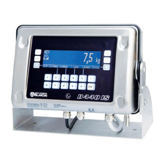
- Page 1 Terminal D440IS and power supplier PS440/xxx – PS440-A/xxx USE AND MAINTENANCE MANUAL Manual code n° 81320122 Edition 05/11/2018...
-
Page 3: Table Of Contents
DS440IS TABLE OF CONTENTS GENERAL MATTERS ........................7 Declaration of conformity ........................7 Foreword............................7 Symbols ............................. 8 Documentation ........................... 9 ATEX certification ..........................10 Description of the terminal ....................... 10 1.6.1 Versions ..........................11 1.6.2 Options ..........................11 Specifications of the terminal ......................12 1.7.1 Terminal D440IS........................ - Page 4 DS440IS Input/Output connection ........................43 How to test the system ........................45 4.8.1 Verification of the compatibility of the system ..............45 4.8.2 How to check the installation ..................... 46 4.8.3 How to check the documentation..................47 CONTROLS, DISPLAY, SWITCHING THE TERMINAL ON AND OFF ........48 Display of weight and additional information ..................
- Page 5 DS440IS OPTIONS ............................. 92 MPP memory expansion boards ...................... 92 7.1.1 Memory capacity ....................... 92 7.1.2 Operation ..........................92 7.1.3 Disabling MPP ........................93 7.1.4 Checking memorised weight data..................94 Optical fibre output option ........................ 94 7.2.1 Connection harness ......................95 7.2.2 Point-to-point mode ......................
- Page 6 DS440IS WARNING Document relating to CESI 00 ATEX 038, CESI 05 ATEX 022 X and CESI 05 ATEX 023 certificates. No changes are permitted without the approval of the "Authorised Person".
-
Page 7: General Matters
DS440IS GENERAL MATTERS Declaration of conformity The declaration of conformity is attached to the safety instructions enclosed with the supply. Foreword The aim of this manual is to provide the operator, through the use of text and illustrations, with essential information regarding the installation, safe operation and maintenance of the weighing system. -
Page 8: Symbols
DS440IS Symbols Below is a list of the symbols used in this manual to alert the reader to the various hazards associated with the operation and maintenance of the instrument. DANGER Denotes an operation or procedure where failure to observe the instructions will result in death or serious injury. -
Page 9: Documentation
DS440IS The hexagon-epsilon-ex symbol indicates an ATEX-certified component that can be installed in zones with potentially explosive gas or dust. The installation is subject to limitations established by the "CE type certificate" issued. The triangle-capital EX symbol indicates an zone where there could be potentially explosive gas or dust. -
Page 10: Atex Certification
DS440IS ATEX certification The terminal has been designed for installation in systems situated in places with potentially explosive dust and/or gas. Terminal D440IS and its power supplier PS440/xxx - PS440-A/xxx have ATEX certification. They are connected to load cells, which are also certified, thus forming a complete weighing system for hazardous zones. -
Page 11: Versions
DS440IS 1.6.1 Versions The weighing terminal can be supplied in the following versions: 230 VAC mains power supply 115 VAC mains power supply 24 VAC low voltage power supply 1.6.2 Options 2 serial outputs in optical fibre ... -
Page 12: Specifications Of The Terminal
DS440IS Specifications of the terminal 1.7.1 Terminal D440IS DANGER Denotes an operation or procedure where failure to observe the instructions will result in death or serious injury. Power supply: from PS440/xxx - PS440-A/xxx Load cells connected: up to eight 700 Ohm analogue cells up to four 350 Ohm analogue cells Minimum impedance: 87.5 ohm... -
Page 13: Power Supplier Ps440/Xxx
DS440IS 1.7.2 Power supplier PS440/xxx PS440/230 VAC power supply 230 VAC (+10% -15%) Standard version 50/60 Hz Pn = 20 VA On Exe terminals PS440/115 Vac 115 VAC (+10% -15%) 115 VAC version 50/60 Hz Pn = 20 VA On Exe terminals PS440/24 Vac power supplier 24 VAC (+10% -15%) Version with very low safety voltage... -
Page 14: Dimensions And Weight Of The Terminal
DS440IS Dimensions and weight of the terminal Weight: 4 kg The dimensions are given in mm. Figure 1.1 - Dimensions and weight of the wall-mounted terminal version... - Page 15 DS440IS Weight: 4 kg The dimensions are given in mm. Figure 1.2 - Dimensions and weight of table top version...
- Page 16 DS440IS Weight: 9 kg The dimensions are given in mm. Figure 1.3 - Overall dimensions and weight of the terminal and power supplier on a single wall support...
-
Page 17: Obtaining Technical Assistance
DS440IS Obtaining technical assistance In the event of any operating faults requiring the intervention of specialised technicians, contact the manufacturer or your nearest Service Centre. To enable us to deal with your request swiftly, always quote the serial number of your terminal, which can be found on the seal label. -
Page 18: Safety Instructions
DS440IS SAFETY INSTRUCTIONS Prohibited uses The instrument you have purchased is a weighing system and has been designed and manufactured as such. The instrument is primarily intended for the weighing of goods. It is forbidden to use the terminal without taking the necessary precautions for safe use. Any other use shall only be permitted if expressly authorised by the Manufacturer. -
Page 19: Compatibility
DS440IS 2.3.2 Compatibility Once the zones and substances have been classified, the equipment can be chosen with protection systems suitable for these zones/substances. 2.3.3 Surface or underground The weighing instruments described in this manual are suitable for use on the surface (group II). 2.3.4 Categories of equipment The appliances are classified in categories, depending on their safety (1, 2, 3). -
Page 20: Groups Of Substances And Surface Temperatures
DS440IS 2.3.5 Groups of substances and surface temperatures The gases present are classified according to the energy and firing temperature (IIC, IIB, IIA and T6..T1). 2.3.6 IP protection degree and surface temperature The casings of appliances installed where dust is present must also possess a certain IP protection degree with a declared maximum surface temperature. -
Page 21: Prescriptions Of Use
DS440IS Prescriptions of use Strictly comply with the instructions in this manual during use. Should you find differences between the contents of this manual and the instrument you have purchased, contact your retailer or the After Sales office of the manufacturer. ... -
Page 22: Document Describing The System
DS440IS DOCUMENT DESCRIBING THE SYSTEM Foreword The applications described in the following paragraphs involve installation and use of ATEX-certified components. Specifications of the components used PS440/xxx – PS440-A/xxx 3.2.1 Certified: CESI 05 ATEX 023 Marking: CESI 05 ATEX 023 II 2(1) G Ex e mb [ia Ga] IIC T5, T4 Gb II 2(1) D Ex tb mb [ia Da] IIIC T100°C, T135°C Db Tamb (- 20°C ÷... -
Page 23: 12X0.35 Mm² Power Supplier-Terminal Connection Cable
DS440IS 3.2.4 12x0.35 mm² power supplier-terminal connection cable Ccable/m <250pF/m Lcable/m<1.5µH/m Insulation voltage=1000V Screened cable 3.2.5 6x0.5 mm² cable for the cells, inputs/outputs, analogue output Ccable<250pF/m Lcable<0.95µH/m Insulation voltage=1000V Screened cable 3.2.6 Optical fibre ... -
Page 24: Sizing The System
DS440IS Sizing the system The cable routes are sized to suit the characteristics of the components used and the electrical specifications given in the certificates. 3.3.1 PS440/xxx D440IS connection Exi circuit - Maximum length = 10 m 3.3.2 Connection of the D440IS scale - Load cells type Eurocell IS/xxx Maximum number of 700 Ohm cells = 8 Maximum number of 350 Ohm cells = 4 Exi circuit - Maximum length from terminal to junction box = 200 m... -
Page 25: Optical Fibre Connection
DS440IS 3.3.7 Optical fibre connection The following can be used between D440IS and RS232 fibre adapter in a safe zone or between two D440IS in a hazardous zone: 200 µm HCD for sections of up to 500m Only compatibility with Fort Fibre TR60 modules is guaranteed. Global protection characteristics of the system 3.4.1 For ambient temperatures of up to +40°C... -
Page 26: Delivery And Installation
DS440IS DELIVERY AND INSTALLATION Accesses 4.1.1 D440IS accesses Access 1, PG11 cable clamp - suitable for cables with external sheath diameter ranging from 5 to 10 mm Exi supply input from PS440/xxx – PS440-A/xxx Access 2, closed by a cap - do not use Access 3, PG11 cable clamp - suitable for cables with external sheath diameter ranging from 5 to 10 mm ... -
Page 27: Ps440/Xxx Power Supplier Accesses
DS440IS 4.1.2 PS440/xxx power supplier accesses M16x1.5 Black cable clamp - suitable for cables with external sheath diameter from 5 to 10 mm Mains power input M16*1.5 Black cable clamp - suitable for cables with external sheath diameter from 5 to 10 mm Output cable input M16*1.5 Blue cable clamp - suitable for cables with external sheath diameter from 5 to 10 mm ... -
Page 28: Connection Of The Terminal To The Electrical Supply Line
DS440IS Connection of the terminal to the electrical supply line DANGER Check the following: the voltage and frequency of the PS440/xxx - PS440-A/xxx power supplier correspond to the indications on the warning plate affixed to the bottom of the terminal; ... - Page 29 DS440IS DANGER Arrange for a connection to the electricity main that is adequately protected: against mechanical damage and chemical corrosion; against heating. The socket must be equipped with a disconnector. Bipolar knife switch (at the customer's care) Power cable (at the customer's care) L-N-T Power input access PS440/xxx –...
- Page 30 DS440IS Power input cable clamp Exe terminals - (L= LINE – T= YELLOW/GREEN = Ground – N= Neutral). Refer to the label affixed to the actual instrument. Label indicating the version of the power supplier and applicable voltage Figure 4.4 - View of internal terminals for connecting power supply to PS440/xxx CAUTION Maximum use conditions: PS440/230: 230 VAC (+10% -15%)
- Page 31 DS440IS Power input cable clamp Exe terminals - (L= LINE – T= YELLOW/GREEN = Ground – N= Neutral). Refer to the label affixed to the actual instrument. Label indicating the version of the power supplier and applicable voltage Figure 4.4.a - View of internal terminals for connecting power supply to PS440-A/xxx CAUTION Maximum use conditions: PS440-A/230: 230 VAC (+10% -15%)
- Page 32 DS440IS Access 1 - Shielding braid turned back over the cable clamp and connected to the chassis Exi output - Insulated shielding braid Double conductor 12x0.35 mm² screened cable JALIM terminal boards on D440IS JOUT-CPU terminal boards on D440IS Terminals 9-19 on PS440-A/xxx Figure 4.5 - PS440/xxx connection to D440IS...
- Page 33 DS440IS Access 1 - Shielding braid turned back over the cable clamp and connected to the chassis Exi output - Insulated shielding braid Double conductor 12x0.35 mm² screened cable JALIM terminal boards on D440IS JOUT-CPU terminal boards on D440IS Terminals 9-19 on PS440-A/xxx Figure 4.5.a - PS440-A/xxx connection to D440IS...
-
Page 34: Opening The Terminal For Access To The Internal Terminals
DS440IS Opening the terminal for access to the internal terminals DANGER The terminal can only be opened up and closed again by specialised personnel. Comply with the following instructions to open the terminal: make sure that there is no potentially explosive gas or dust; ... - Page 35 DS440IS DANGER Make sure that the seal is correctly positioned and seated when the cover is fitted back on. The IP54 protection degree of the casing will be impaired if the seal is positioned incorrectly. DANGER Take care of the ground connection soldered between the front and rear casing when removing the upper cover.
- Page 36 DS440IS Optional connectors Ground connections Figure 4.7 - Opening the terminal and view of the internal parts...
-
Page 37: Internal Terminal Connections
DS440IS 4.3.1 Internal terminal connections JALIM - Exi power input from PS440/xxx - PS440-A/xxx JOUT_CPU -Command output towards PS440/xxx - PS440-A/xxx JINPUT_EXI - Exi input JCELL - Exi scale input Protective scale input cover Figure 4.8 - Internal terminal connections... -
Page 38: Connection To The External Devices
DS440IS Connection to the external devices The cable clamps on the bottom of the instrument allow connection to the screen earth. With the exception of the optical fibre cables, each cable that enters the instrument must be of the screened type. Strip the cable to the length required for internal connection so as to earth the screen, as indicated in the following figures. -
Page 39: Connection Of The Terminal To The Platform Scale
DS440IS DANGER Plug any unused cable clamps. Connection of the terminal to the platform scale To connect the terminal to the weighing platform, the supply includes a pre-wired cable the connector of which must be inserted into the 6-pin terminals (JCELL) (point 4 of Figure 4.8 on page 1-36) after having removed the protective scale input cover (point 5 of Figure 4.8 on page 1-36). -
Page 40: Analogue Cell Connection
DS440IS 4.5.1 Analogue cell connection The pinout diagram for terminal JCELL when connected to platforms formed by analogue cells is given below. TERMINAL JCELL Jcell connector Description SIG+ Signal + SIG - Signal - EX+_EX Power supply + EX-_EX Power supply - SENSE+ Sense + SENSE-... -
Page 41: Output Connection
DS440IS Output connection Output contacts are available in the terminal board of power supplier PS440/xxx - PS440-A/xxx (point 1 Figure 4.8 on page 35). The wiring diagram is given below. Description OUTPUT 1 OUTPUT 2 Refer to the label affixed to the actual instrument. OUTPUT 3 OUTPUT 4 Terminal board of power supplier PS440-A/xxx... - Page 42 DS440IS Terminal board of power supplier PS440-A/xxx Figure 4.9.a - Output connection CAUTION Technical features (see safety instructions Ps440-A) Output of the MOS type: Features ATEX Uo = 13,4V, I or = 79th, Po = 0,32W Maximum operating voltage = 12 VDC Maximum operating current = 50 mA Refresh time I / O = 1.10 s DANGER...
-
Page 43: Input/Output Connection
DS440IS Input/Output connection Intrinsic safety input contacts are available in the terminal board JINPUT_EXI at the rear of the indicator (point 3 Figure 4.8 on page 1-36). The wiring diagram is given in Figure 4.10 on page 1-42. Pi = Part inside terminal Pe = Part outside terminal Figure 4.10 - JINPUT_EXI terminal board for Input/Output connections CAUTION... - Page 44 DS440IS DANGER When the weighing system is installed in complex plants that can represent a danger hazard for operators, enlist the assistance of specialised personnel to perform several manoeuvres without load in order to acquire the experience necessary to work in safety.
-
Page 45: How To Test The System
DS440IS How to test the system The various tests to which the newly installed weighing system must be subjected are outlined below. The following points are only a specific recap. Consult complex standard EN60079-17 for full testing and servicing instructions. 4.8.1 Verification of the compatibility of the system At the charge of the person in charge of safety in the company. -
Page 46: How To Check The Installation
DS440IS 4.8.2 How to check the installation At the installer's charge. Make sure that the devices used to fix the casing of PS440/xxx - PS440-A/xxx and D440IS are efficient. Make sure that the devices used to fix the junction boxes and connection cables are efficient. ... -
Page 47: How To Check The Documentation
How to check the documentation The following documentation is consigned to the customer: Document describing the system (only if it is installed by Coop Bilanciai). An operation and maintenance manual for the terminal/power supplier (the manual you are now reading). -
Page 48: Controls, Display, Switching The Terminal On And Off
DS440IS CONTROLS, DISPLAY, SWITCHING THE TERMINAL ON AND OFF Display of weight and additional information Weighing function keys Display of weight and additional information Alphanumeric keys Figure 5.1 - Front of terminal The LCD (Liquid Crystal Display) (point 2 Figure 5.1 on page 1-47), in addition to the universally recognised weighing symbols, also displays information (in extended format) related to the operation of the terminal. - Page 49 DS440IS Listed below are the weighing symbols displayed and their meanings: Weight stable symbol Indicates that the weight value displayed is stable and thus may be printed and/or transmitted. Centre zero symbol Indicates that the weight on the scale is near to zero i.e. within -1/4 + 1/4 of a division.
-
Page 50: Selection Display Symbols
DS440IS 5.1.1 Selection display symbols Weight indication Below preset lower limit. Weight indication Within the preset upper and lower limits. Weight indication Above the preset upper limit. -
Page 51: Weighing Function Keys
DS440IS Weighing function keys Refer to point 1 of Figure 5.1 on page 1-47: Zero-set weight pressing this key resets the weight indication only if the following condition are satisfied: the weight value must be within the -1% ÷ +3% range of the weighing capacity for terminals subject to legal verification or ±... - Page 52 DS440IS Enter/display tare Pressing this key allows you to enter a tare value using the numeric keys on the keypad (par. 5.3 on page 1-52). To change a preset tare value see par. 6.2.11 on page 1-66. On completion of the operation, the display will show the net weight and tare values and illuminate the symbols .
-
Page 53: Alphanumeric Keys
DS440IS Alphanumeric keys Refer to point 3 of Figure 5.1 on page 1-47: Keys for entering numeric values and alphanumeric characters Key for entering decimal digits Use this key for entering decimal values. Enter or confirm Press to confirm an operation. WARNING The functions of the keys may vary and are indicated on the display. -
Page 54: Switching The Terminal On And Off
DS440IS Switching the terminal on and off Bipolar knife switch (at the customer's care) Power cable (at the customer's care) L-N-T Power input access PS440/xxx - PS440-A/xxx Exi D440IS power cable 6 mm² cable ground/earth connection (at the customer's care) Figure 5.2 - Terminal connection to the electricity main DANGER Make sure that the protective casing is in a perfect condition before powering the terminal. - Page 55 DS440IS Operate the disconnector switch. With power on, the display will show the Manufacturer's logo and the type of operation for which the terminal is enabled (see par. 6.4 on page 1-73). Wait for the LOCK indication to appear (terminals subject to metrological verification only). If on completion of the operation the display shows a value other than zero, press to zero-set the reading.
-
Page 56: Using The Terminal
DS440IS USING THE TERMINAL GENERAL MATTERS 6.1.1 Using the keys to navigate the menus The numeric keys described in par. 5.3 on page 1-52 and the customisable keys par. 5.2 on page 1-50 can be used to navigate the programming menus. -
Page 57: Entering Numeric Data (Editor)
DS440IS 6.1.2 Entering numeric data (Editor) Numeric values may be entered as follows: select the function for which you wish to enter the value (preset tare, settings, range...); the display will show the selected function with the value currently stored in memory; ... - Page 58 DS440IS prolonged pressure on a key will display all the characters associated with that key. By moving left and right with the keys and you can select the character you wish to enter. The selected character is displayed in reverse video. Confirm the selection by pressing OK . To toggle between upper and lower case letters, press the key in correspondence with the indication CAPIT/SMALL.
-
Page 59: Shortcut Keys
DS440IS 6.1.4 Shortcut keys During installation, User menu functions may be assigned to shortcut keys. In this way the user can access the required function more rapidly. For example, to access the function Product Code, the user will not have to press ...MENU>Data Management>Code Management>Product Code but simply press PROCOD. -
Page 60: User Menu
DS440IS User menu 6.2.1 Adjusting the contrast To adjust the contrast of the display, follow the pathway: ...>MENU>Contrast (Shortcut key CONTR). By pressing + or - you can adjust the contrast. To save the new setting in memory press SAVE. 6.2.2 Changing the date and time Follow the pathway:... - Page 61 DS440IS Selection In addition to the weight and the usual weighing symbols, the display shows one of the following symbols (see par. 5.1.1 on page 1-49). To set the range, press DRANGE, select the values with SELECT and enter the numerical values using the number keys (par.
- Page 62 DS440IS NOTE: the indication Tare C indicates that the tare displayed is a "coded" tare to which a numerical code has been assigned (par. 6.2.10 on page 1-65). If multiple tares were set during installation: Tare T: acquired tare value + unit of measurement Tare 1 PT: preset tare 1 value + unit of measurement Tare 2 PT: preset tare 2 value + unit of measurement Tare C PT: preset tare value + unit of measurement...
-
Page 63: Memory Status
DS440IS Customised Can be selected when display customising is available. 6.2.4 Memory status If there is insufficient free memory, memory can be recovered by following the pathway: ...>MENU>Memory status CAUTION The memory recovery operation may require a few minutes during which time the terminal cannot be operated. -
Page 64: Setting The Outputs As Ranges (If Enabled)
DS440IS 6.2.7 Setting the outputs as ranges (if enabled) The two available outputs may be used in Range mode. The output is activated when the weight is within the set range; to set the range, follow the pathway: ...>MENU>Data management>Range (Shortcut key RANGE). -
Page 65: Product Code
DS440IS 6.2.9 Product code The terminal can handle product codes, each of which can be matched to: an alphanumerical description, which can be printed and/or transmitted along with the weight; a preset tare (match defined during the installation phase); ... -
Page 66: Product Code List
DS440IS 6.2.10 Product code list By following the pathway: ...>MENU>Data Management>Code Management>Product c.List the actual description of the code can be displayed by recalling the product code in question. CODE allows the operator to enter the product code and all the data associated with it. The code entered becomes the activated element. -
Page 67: Preset Tares
DS440IS 6.2.11 Preset tares In addition the management of tares acquired from the weight present on the scale and tares entered from the keypad, the terminal also manages an archive of preset tares containing a number of values defined during the installation phase. Each value can be recalled by way of a 4 digit numeric code. -
Page 68: Preset Tare List
DS440IS 6.2.12 Preset tare list By following the pathway: ...>MENU>Data Management>Preset tare>List the corresponding tare value can be displayed by recalling the tare code in question. CODE allows the operator to enter the tare code and the value of the tare associated with it. The tare code entered becomes the activated element. -
Page 69: Progressive Number
DS440IS 6.2.13 Progressive number The terminal manages a 6-digit progressive number used to count the number of weighing operations performed: this value starts from 1 and is automatically increased by one unit after each print and/or weighing operation (and thus indicates the value of the next print or weighing operation). To change the progressive number, follow the pathway: ...>MENU>Data management>Progressive (Shortcut key PROG.N) -
Page 70: Totals Management
DS440IS 6.2.16 Totals management The terminal provides functions for totalling the weighing data associated with the various codes. The totalization operation consists of adding the current weight value to the sum of the previous weights and increasing by one the number of weighing operations. To access the list of available totals, follow the pathway: ...>MENU>Totals management (Shortcut key TOTALS) -
Page 71: User Menu Access
DS440IS prints out the selected total SUMMAR total print of a group of codes RESET resets the selected total CODE selects the code LIST displays the list of totals Within the LIST menu, you can select SUMMAR , RESET, CODE (with the functions explained above) and ENTER , which displays the individual selected total. -
Page 72: Printing Weighing Data
DS440IS Printing weighing data The printer is normally connected to the terminal by way of the COM1 serial port (par. 7.3 on page 1- 97). Printouts are obtained by pressing . Printing is performed if: the weight is valid, i.e. it is not less than zero and does not exceed the maximum scale capacity; ... -
Page 73: Weighing Data Reprint
DS440IS 6.3.1 Weighing data reprint Access the Reprint item of the user menu to obtain the last printout again without having to change the consecutive number and any totals calculated. The word Copy will appear on the reprint to distinguish it from the original. 6.3.2 Automatic print-out If enabled, allows automatic printing once the stable weight has been obtained. -
Page 74: Operating Modes
DS440IS Operating modes The terminal operating mode is set during installation. On switching on the terminal, the selected operating mode is displayed. Standard operation In standard operating mode, the terminal can acquire the gross (or net) weight on the scale and display it along with the weighing symbols. -
Page 75: Unloading Extraction Operation
DS440IS Unloading extraction operation This operating mode is identical to the previous mode except that in this case you start with a loaded scale and gradually remove material. Enter the Set Point 01 and Set Point 02 values (par. 6.2.6 on page 1-62). On pressing the key in correspondence with the indication START, the extracted weight value is zero-set and scale unloading is enabled. - Page 76 DS440IS If zero (0%) is entered, the terminal will NOT make any fall correction. Even if they can be totalized, the cycles interrupted with "stop" are NEVER subjected to any fall correction. Fall correction example. Requested quantity = 23.5kg Fall = 3.5kg fall correction % = 10% Final quantity extracted = 26.7kg Difference between extracted and requested quantities = Error = 26.7 - 23.5 = 3.2kg Correction value = Error * correction % / 100 = 3.2*10/100 = +0.32kg New Fall value = old fall value + (correction value) = 3.5 + (+0.32) = 3.82kg...
-
Page 77: Extraction Totals
DS440IS 6.8.2 Extraction totals Each extraction cycle that terminates correctly in all phases (i.e. extraction and possible printout), or with negligible problems (i.e. an extraction terminated with stop but with a cycle defined as being able to be totalized and/or a cycle printout terminated with a printer fault but with a cycle defined as being able to be totalized), leads to an increase in the progressive number and the forms of totalizing enabled (general total, partial total, total by product code, total by generic code), as well as the specific extraction total. -
Page 78: Start Key
DS440IS 6.8.3 START key The "START" key is located at the bottom right-hand side of the display and pressure on it is interpreted by the terminal as a request to start an extraction cycle. The terminal checks to make sure that a different "requested quantity" value from zero has been entered, that the weight on the scale is valid (no error in the weight converter and scale not overloaded) and that it is within the "initial range"... -
Page 79: Data Displayed With Extraction Activated
DS440IS 6.8.4 Data displayed with extraction activated The following information is displayed in this page: the gross weight measured by the scale (preceded by the word "Weight") and its metrological indications (stable weight, center zero, minimum weight indications, etc.); ... -
Page 80: Operating Principle Of Extraction
DS440IS 6.8.5 Operating principle of extraction The terminal deactivates the output contact called "slow" when the extracted quantity reaches the value given by the (requested - slow - fall) difference. The terminal deactivates the output contact called "requested" when the extracted quantity reaches the value given by the (requested - fall) difference. -
Page 81: Numeric Example Of An Extraction Cycle
DS440IS 6.8.6 Numeric example of an extraction cycle Supposing that the following data have been entered: Requested quantity = 23.5kg Slow = 4.2kg Fall = 1.5kg Fall correction %= 10% If the conditions are correct, the "requested" and "slow" outputs will be activated on start. The terminal deactivates the "slow"... -
Page 82: Error Messages
DS440IS 6.8.7 Error messages Request not valid. This appears when the user requests an extraction cycle to be started and the value entered as requested quantity is not higher than zero. The cycle request is annulled. Initial range error. This appears when the user requests an extraction cycle to be started and the value entered as "maximum initial weight"... -
Page 83: Double Weighing Mode
DS440IS 6.10 Double weighing mode DOUBLE WEIGHING options are most commonly used for weighing means of transport, which are weighed prior to loading (entry weighing) and then again after loading (exit weighing) to determine the quantity of goods that are being transported. Double weighing options can be done with: ... -
Page 84: Entry/Exit Functions With Data Recall
DS440IS 6.11 Entry/Exit Functions with Data Recall This type of procedure is enabled during the installation phase. The two weighing phases for entry and exit do not necessarily have to be consecutive. The difference between the entry and exit weights can be calculated at the time of the second weighing. 6.11.1 Entry weighing procedures For each entry print-out, the terminal allocates and prints out a code (the RCD code). - Page 85 DS440IS The data printed out are: date time progressive number a product code with details a client code with its details plate RCD code first weight The data relating to the first weighing operation are held in the memory until the second weight is printed out.
-
Page 86: Exit Weighing Procedures
DS440IS 6.11.2 Exit weighing procedures The terminal is able to print out the second weight only after the operator has recalled the RCD code of the first weight. Proceed in the following way: Press key RCD . The last RCD code used is displayed along with the associated data. ... -
Page 87: Unused Rcd Code Recovery
DS440IS Printing will take place only if: the weight stabilises within 10 seconds; the weight is not negative or over the maximum weight capacity. The data printed out depend on the printer connected or the configuration chosen for the first weighing. -
Page 88: Entry/Exit Operations Using Licence Plate Data Recall
DS440IS 6.12 Entry/Exit operations using Licence Plate Data Recall The RCD Plate code is made up of as maximum of 10 alphanumerical characters which the operator enters manually and which must be set before each entry weighing operation. Refer to par. 6.11.1 on page 1-83 and par. 6.11.2 on page 1-85 for the entry/exit procedure. In this case, the reference key is not RCD but PLATE. -
Page 89: Preset Weight Options
DS440IS 6.13 Preset weight options The preset weight options are used when the first weight (or tare) of a vehicle is known and therefore does not need to be weighed. The preset weights are associated with a code that can be used to recall them. Besides the preset weight, each code can also store auxiliary information such as the product code or the client code. -
Page 90: Weighing Procedures With Preset Weights
DS440IS 6.13.2 Weighing procedures with preset weights Once the vehicle is on the weighing scales, press the RPD (or PPLATE) key and enter the desired code to recall the first weight preset by the list. The weight on the scales, the preset weight code and the preset weight will appear on the display. Press for a print-out of the weight. -
Page 91: Total Management
DS440IS 6.15 Total management Besides the totals already described in the user manual in par. 6.2.16 on page 1-69, the following generic totals can be made in the double weighing mode Totals for Client Code Totals for Plate Code The net weights and number of weighing operations associated with a given client code or a given plate code are memorised. -
Page 92: Options
DS440IS OPTIONS MPP memory expansion boards Terminals provided with the MPP option (permanent weight memory) can memorise the weight data of each individual weighing operation in a permanent memory and transmit the value to an external peripheral along with an identifying code ascribed by the terminal itself. It is possible to check whether the data item is correct by entering the identification code in the weighing terminal. -
Page 93: Disabling Mpp
DS440IS 7.1.3 Disabling MPP It may sometimes occur that you do not wish to transfer the weight data or save it in the MPP memory. In this case, to disable MPP, type: ...>MENU> MPP operation>De-activated To subsequently re-enable MPP operation: ...>MENU>MPP operation>with memory WARNING Disabling MPP may compromise the operation of equipment connected to the weighing system in... -
Page 94: Checking Memorised Weight Data
DS440IS 7.1.4 Checking memorised weight data To check the data saved in memory, press the shortcut key COD MPP. The terminal displays the net weight and the tare associated with the MPP identification code of the last weighing operation to be performed. By pressing SETCOD you can call up previous weighing operation data by entering the relative code number (see par. -
Page 95: Connection Harness
DS440IS 7.2.1 Connection harness A convention has been used to identify the connectors. 1. Each fibre begins and ends with 2 different coloured connectors (blue and black). 2. The harness connectors fit into the ones on the board with the same colours. N = Black B = Blue Figure 7.2 - Harness example... -
Page 96: Point-To-Point Mode
DS440IS 7.2.2 Point-to-point mode The COM1 port is generally used to connect printers, a PC or a slave. 7.2.3 Optic loop mode Besides operating in the one-by-one manual mode like COM1, the COM2 port can also function in the OPTIC LOOP mode. The OPTIC LOOP mode is used in a network of terminals. -
Page 97: Optical Fibre Adapter - Rs232 (Fo-232)
DS440IS 7.2.4 Optical fibre adapter - RS232 (FO-232) The optic signal is transferred to RS232 by means of an adapter of the "FORT FIBRE OTTICHE MOD. TR60" type. DANGER Do not use other types of adapter as this would fail to comply with the document describing the system. -
Page 98: Printers
DS440IS Printers The printer is usually connected to the terminal by way of the COM1 serial port (Figure 4.8 on page 1-36), although in some exceptional cases it may be connected to the COM2 port. For special connections, refer to the order documentation. For information regarding the printer characteristics and maintenance, replacement of paper, ribbon, fuses, etc., refer to the printer instruction manual. -
Page 99: Connection To Stb112 In Rs232, -Tm295, Tmu295, Lx300+, Italora
DS440IS 7.3.2 Connection to STB112 in RS232, -TM295, TMU295, LX300+, ITALORA Printer COM1 Optical fibre adapter - RS232 25-pin male Optical fibre receiver - Blue Optical fibre transmitter - Black Jumpers on DTE (2-TX, 3-RX) Figure 7.6 - Connection to STB112... -
Page 100: Connection To A Pc
DS440IS Connection to a PC 9-pin female - 25-pin male adapter Optical fibre adapter - RS232 25-pin female Optical fibre receiver - Blue Optical fibre transmitter - Black Jumpers on DTE (2-TX, 3-RX) COM1 Figure 7.7 - Connection to a PC... -
Page 101: Ma Analogue Output
DS440IS 4-20 mA analogue output Power supply from JALIM J1 terminal boards on optional board 6x0.5 mm² screened cable Exi circuit. Insulate shielding braid and conductors that are not used. Access 4. Shielding braid turned back over the cable clamp and connected to the chassis Figure 7.8 - 4-20 mA with internal power supply... - Page 102 DS440IS External power supply J2 terminal boards on optional board 6x0.5 mm² screened cable Exi circuit. Insulate shielding braid and conductors that are not used. Access 4. Shielding braid turned back over the cable clamp and connected to the chassis Figure 7.9 - 4-20 mA with external power supply CAUTION Technical specifications:...
- Page 103 DS440IS DANGER The shielding braid must be turned back over the cable clamp and connected to the chassis. It should be insulated on the other side. Read the "Safety notes" for further information about the connections.
-
Page 104: Maintenance
DS440IS MAINTENANCE Lithium battery On switching on the terminal, it performs a check on the condition of the internal lithium battery. If the battery is discharged, the terminal displays the message CHANGE THE BATTERY. To change the battery, contact Assistance Service. Casings Prevent dust from building up on the power supplier and terminal casings. - Page 105 DS440IS...
-
Page 106: Troubleshooting
DS440IS TROUBLESHOOTING If the suggested remedy does not solve the problem, contact Assistance Service. Malfunctions Problem Cause Remedy The terminal does not switch on No power Check that power arrives at the mains outlet socket. Check that the mains lead is correctly plugged in. -
Page 107: Error Messages
DS440IS Error messages Problem Cause Remedy 9999999 The scale is overloaded. Reduce the weight to a value flashing below the maximum scale capacity. -01- Converter fault. Contact Assistance Service. Scale connector disconnected or Switch off the terminal and check broken. that the connector is properly connected. - Page 108 DS440IS Change the battery Internal lithium battery discharged Contact Assistance Service Weight not valid The scale is in negative weight or See conditions for correct printing overload condition and the printer in par. 6.3 on page 1-71. does not print Printer error Printer switched off or Check printer is connected and...
- Page 109 DS440IS...
- Page 110 Società Cooperativa Bilanciai Campogalliano - 41011 Campogalliano (MO) Italy Via S. Ferrari, 16 - Tel. +39 (0)59 893 611 - Fax +39 (0)59 527 079 Web: http://www.coopbilanciai.it - E-mail:cb@coopbilanciai.it Servizio Assistenza Clienti Tel. +39 (0)59 893 612 - Fax +39 (0)59 527 294...
Need help?
Do you have a question about the PS440 Series and is the answer not in the manual?
Questions and answers