Bilanciai DD1010 Use, Maintenance And Installation Manual
Weighing terminal
Hide thumbs
Also See for DD1010:
- Use, maintenance and installation manual (132 pages) ,
- Quick start (4 pages) ,
- Quick start (2 pages)

Related Manuals for Bilanciai DD1010


Summary of Contents for Bilanciai DD1010
- Page 1 DD1010 WEIGHING TERMINAL USE, MAINTENANCE AND INSTALLATION MANUAL Edition 01/02/2013 Manual code n°81320431...
-
Page 3: Table Of Contents
DD1010 TABLE OF CONTENTS INTRODUCTION..........................3 Foreword............................3 Documentation ........................... 4 Symbols ............................. 4 Description of the terminal ......................... 5 Specifications of the terminal ......................6 Declaration of Conformity ........................7 Overall dimensions and weight of terminal ..................7 1.7.1 Plastic version ........................ - Page 4 DD1010 REMOVING COMPONENTS ....................... 34 11.1 Removing support (stainless steel version only) ................34 11.2 Opening the terminal ........................35 11.2.1 Plastic version ........................35 11.2.2 Stainless steel version ....................... 36 11.3 Removing front panel and display ....................37 11.3.1 Plastic version ........................
-
Page 5: Introduction
DD1010 INTRODUCTION Foreword • The purpose of this manual is to inform the operator, by means of texts and figures, of the basic rules and criteria which must be observed to correctly install, safely use and regularly maintain the weighing unit. -
Page 6: Documentation
DD1010 Documentation Standard documentation supplied with the DD1010 terminal consists of: • QUICK START multi-language, hard copy, quick reference guide for immediate use, declaration of conformity and main hazard information. • USE, MAINTENANCE AND INSTALLATION MANUAL Multi-language, PDF, hard copy available upon demand. -
Page 7: Description Of The Terminal
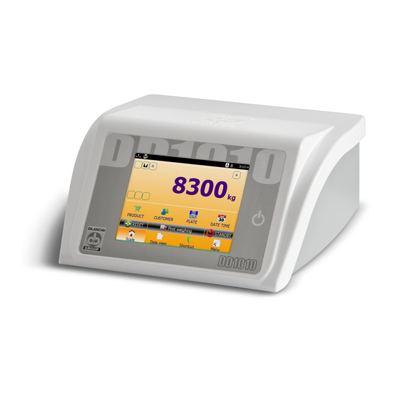
DD1010 Description of the terminal The DD1010 terminal performs highly accurate and reliable weighing. • Especially designed for industrial applications. • Supplied with metrological software required for weighing management. • ABS and stainless steel enclosure; available both in the tabletop and wall-mounted versions. -
Page 8: Specifications Of The Terminal
DD1010 Specifications of the terminal Power supply Direct 12 VDC/3 A (Min. 11 V - Max. 15 V) Via network adapter L+N+R 110 - 240 VAC (-15% … +10%) 1.8 A 50 - 60 Hz 60W Max. Earth connection system... -
Page 9: Declaration Of Conformity
DD1010 Communication ports USB Type A 2 (+1 internal) Serial ports 1 rs232/ rs422 optoinsulated- 1 rs232 Ethernet 10/100 Memories SD Board Expansions Optional board slots Declaration of Conformity See QUICK START manual. Overall dimensions and weight of terminal 1.7.1... -
Page 10: Stainless Steel, Tabletop Version
DD1010 1.7.2 Stainless steel, tabletop version Figure 1.7-2 - Dimensions of the weighing terminal, stainless steel tabletop version • Dimensions (in mm): see figure 1.2. • Weight: 5 kg 1.7.3 Stainless steel, wall-mounted version Figure 1.7-3 - Dimensions of the weighing terminal, stainless steel, wall-mounted version •... -
Page 11: Instructions For Disposal Of Electrical Or Electronic Waste Material
DD1010 Instructions for disposal of electrical or electronic waste material This symbol on the weighing instrument means that: • this electrical/electronic instrument cannot be disposed of as municipal solid waste. • It must be disposed of separately. • It can be handed over to the distributor when purchasing a new instrument. -
Page 12: Spare Parts
TYPE A L=15 CM FLAT CABLE ZIF FPC 40-PIN PITCH 0.5MM TOP-TOP CONTACTS 1.11-2 54830006 TOP-TOP TYPE A L=35 CM DD1010 ST. STEEL VERSION WITH CABLE LUGS AND DIRECT OUTPUTS. POWER SUPPLY SWITCHING POWER SUPPLY 100-240VAC/12VDC 1.11-1 52050019 OUTPUT 12VDC/60WATT, IEC SOCKET, 2 FERRITE CABLE CORE AND 4-PIN OUTPUT POWERDIN, CUSTOMISED SWITCHING POWER SUPPLY 88-264VAC/12VDC IOUT=2.1A 25W,... - Page 13 DD1010 Figure 1.11-1 – Spare parts for plastic terminal Figure 1.11-2 - Spare parts for tabletop and wall-mounted stainless steel version...
-
Page 14: Safety Rules
DD1010 SAFETY RULES Prohibited uses The instrument you have purchased is a weighing system and has been designed and manufactured as such. Its main purpose is therefore weighing goods. • It is therefore prohibited to use the terminal without the necessary precautions for safe use. -
Page 15: Delivery And Installation
DD1010 DELIVERY AND INSTALLATION Figure 3-1 – Bottom side of the terminal with connectors Key: 1. Optional board slots 2. Scale 1 3. Scale 2 4. COM2 port 5. COM1 port 6. Expansion for SD card 7. Ethernet port, 10/100 Mb 15/5 8. - Page 16 DD1010 Figure 3-2 – Bottom side of terminal with cable lugs Key: 1. Optional board slots 2. Scale 1 3. Scale 2 4. COM2 port 5. COM1 port 6. Expansion for SD card 7. Ethernet port, 10/100 Mb 15/5 8. USB HOST ports...
-
Page 17: Installation
DD1010 Installation ATTENTION This terminal must be installed indoors, sheltered against atmospheric agents, since it has not been designed to resist adverse weather conditions. 3.1.1 Tabletop installation Place the terminal on a stable surface (table or bench without wheels) and make sure that the monitor is not exposed to direct light to avoid reflections. -
Page 18: Connection Diagram (Version With Connectors)
DD1010 3.2.2 Connection diagram (version with connectors) To ensure correct connection of the terminal to the mains, proceed as follows: • Connect the terminal to the power supply unit; • Plug the power supply unit into the socket using the cable provided. -
Page 19: Connection Diagram (Version With Cable Lugs)
DD1010 WARNING The size and installation of the power supply cable and of the disconnector switch are at the customer's care. 3.2.2 Connection diagram (version with cable lugs) Connection to the power supply line is at the installer's care. The customer must provide, by means of qualified personnel, installation of the earth conductor and power supply cable. - Page 20 DD1010 DANGER Check that: • the voltage and frequency of the electrical supply line correspond to the indications on the sealing plate on the bottom of the terminal; • the mains outlet socket to which the terminal is connected is equipped with an earth;...
-
Page 21: Connecting The Terminal To The Weighing Platform
DD1010 CONNECTING THE TERMINAL TO THE WEIGHING PLATFORM For connection of the terminal to the weighing platform, a cable harness is provided, the female connector of which must be inserted into the 9/15 pin male connector (JBIL) at the bottom of the indicator. -
Page 22: Connection Diagram (Platform)
DD1010 3.3.1 Connection diagram (platform) Figure 3.4-1 – Connection of terminal to scale Key: 1. Weight display terminal. 2. Weighing platform or weighbridge. 3. Scale cable with 9/15 pin connector. 4. Scale input 5. Equipotential cable with cable terminal eyelets. -
Page 23: Serial Connection Of Digital Scale
DD1010 3.3.3 Serial connection of digital scale 15-pin female connector DESCRIPTION 485- EX + EX + EX - EX - 485+ EX - NC = do not connect Connection towards digital cells is ensured to RS485 serial transmission using a shielded cable with 6 wires. -
Page 24: Serial Connections
DD1010 SERIAL CONNECTIONS 3.4.1 COM1 serial connection 9-pin female connector DESCRIPTION RX422 - RX232 TX232 RX422 + TX422 - TERMINATOR TX422 + NC = do not connect 3.4.2 COM2 serial connection 9-pin female connector DESCRIPTION RX 232 TX 232 J24 OFF = DISCONNECTED... -
Page 25: Rs232 Connections
DD1010 3.4.3 RS232 connections ATTENTION Operating limits stipulated by the standard RS232: Max. transmission distance: 15 m Maximum voltage at ends: ± 12 Vdc For connection to external devices, it is recommended to use a shielded cable, making sure to connect the shield to the metal part of the 9-pin connector's casing. -
Page 26: Controls - Turning On And Off
DD1010 CONTROLS - TURNING ON AND OFF ON/OFF key After connecting the terminal to the power supply by means of the power supply unit, turn on the terminal by pressing the key at the front. Figure 4.1-1 – Turning on After 3 seconds, the light blue LED, signaling that the terminal is on, will flash 3 times. - Page 27 DD1010 Figure 4.1-2 – Green LED on power supply unit To turn off the system, pull the plug out of the socket.
-
Page 28: Touch Screen
DD1010 Touch screen Commands are given to the terminal via the Touch Screen. You may need to move windows; in this case, press and hold down the horizontal blue bar of the window whilst moving across the screen. The same applies to lateral scroll bars: for instance, to consult the Help section. -
Page 29: Options
DD1010 OPTIONS The DD1010 weighing terminal can be equipped with optional boards, peripherals and accessories. For instructions and installation information, refer to the relative manuals. Some options imply upgrading of firmware. Contact the After Sales Office or Sales-Support Network. Options currently available (upon the date of release of this manual) are: •... -
Page 30: Error Messages
DD1010 ERROR MESSAGES Terminal errors Problem Cause Solution Check the status of the LED on the power supply When the on/off key is unit: pressed, the terminal does The light blue LED is off if it is ON, make sure the connector of point 9 not come on has been correctly plugged in. - Page 31 DD1010 Problem Cause Solution - 01 - Connection to load cell Check extension cord, connector block and load Converter out of order wrong or missing cells (*) Return signal from load - 01 - Make sure the load cell is in working order and...
-
Page 32: Customising Parameters
DD1010 CUSTOMISING PARAMETERS To gain access to parameter customisation, press the TOOLS key. You will therefore display all parameters for operation of the instrument. Not all parameters can be modified. Parameters that cannot be modified are displayed in a different colour: if you click on them, options for modification will not appear. -
Page 33: Access To Metrological Parameters
DD1010 ACCESS TO METROLOGICAL PARAMETERS To gain access to customisation of metrological parameters (parameters relating to legal operation of the scale), you must press the calibration button. 10.1 Version with connectors Figure 10.1-1 – Calibration key – Terminal, plastic version Figure 10.1-2 –... -
Page 34: Version With Cable Lugs
DD1010 Making reference to the previous figures, proceed as follows: • Turn on the terminal. • Remove the adhesive label (ref. 1) sealing the hole for access to the calibration switch. • Use a non-metal tool, activate the calibration switch (ref. 2). -
Page 35: Internal Scale Sampling
DD1010 10.3 Internal scale sampling Follow the path indicated below: “FOLDER” “TOOLS” Select the SCALE Boards (SCALE Tab) Internal scale to sample SAMPLING Choose the type of sampling procedure by following the indications on the display. -
Page 36: Removing Components
DD1010 REMOVING COMPONENTS 11.1 Removing support (stainless steel version only) Figure 11.1-1 – Removing the support Making reference to the previous figure, proceed as follows: • Loosen the fixing knobs (ref. 1). • Remove the support (ref. 2 wall-mounted version) (ref. 3 tabletop version). -
Page 37: Opening The Terminal
DD1010 11.2 Opening the terminal 11.2.1 Plastic version Figure 11.2-1 – Opening the terminal Making reference to the previous figure, proceed as follows: • Remove the four screws (ref. 1) and turn the cover forward, whilst supporting it with your hand to prevent damage to the connections. -
Page 38: Stainless Steel Version
DD1010 11.2.2 Stainless steel version Figure 11.2-2 – Opening the terminal Making reference to the previous figure, proceed as follows: • remove the four screws (ref. 1) and turn the cover sideways, whilst supporting it with your hand to prevent damage to the connections. -
Page 39: Removing Front Panel And Display
DD1010 11.3 Removing front panel and display 11.3.1 Plastic version Figure 11.3-1 – Removing front panel and display Making reference to the previous figure, proceed as follows: • Open the terminal. • Unplug the connectors (ref. 1 and 2) •... - Page 40 DD1010 ATTENTION When refitting, make sure the cables (ref. 1) between display and board are drawn along a Z- shaped route, as shown in the figure. Figure 11.5 – Refitting front panel and display...
-
Page 41: Stainless Steel Version
DD1010 11.3.2 Stainless steel version Figure 11.3-2 – Removing front panel and display Making reference to the previous figure, proceed as follows: • Open the terminal. • Unplug the connectors (ref. 1 and 2) • Loosen the four screws (ref. 3) and remove the board and display from the front section of the terminal. - Page 42 DD1010 ATTENTION When refitting, make sure the cables (ref. 1) between display and board are drawn along a Z- shaped route, as shown in the figure. Figure 11.7 – Refitting front panel and display...
-
Page 43: Removing Terminal Power Supply Unit (Stainless Steel Version With Cable Lugs Only)
DD1010 11.4 Removing terminal power supply unit (stainless steel version with cable lugs only) Figure 11.4-1 – Removing terminal's power supply unit Making reference to the previous figure, proceed as follows: • Open the terminal. • Disconnect the power supply unit's connector (ref. 1) from the board ( J25 pin1 +Vdc / pin2 GND •... -
Page 44: Removing Power Supply Unit For Digital Scale
DD1010 11.5 Removing power supply unit for digital scale 11.5.1 Plastic version Figure 11.5-1 – Removing power supply unit for digital scales Making reference to the previous figure, proceed as follows: • Open the terminal. • Remove the power supply unit for digital scales (ref. 1) by pulling gently. -
Page 45: Stainless Steel Version With Connectors
DD1010 11.5.2 Stainless steel version with connectors Figure 11.5-2 – Removing power supply unit for digital scales Making reference to the previous figure, proceed as follows: • Open the terminal. • Remove the power supply unit for digital scales (ref. 1) by pulling gently. -
Page 46: Stainless Steel Version With Cable Lugs
DD1010 11.5.3 Stainless steel version with cable lugs Figure 11.5-3 – Removing power supply unit for digital scales Making reference to the previous figure, proceed as follows: • Open the terminal. • Remove the terminal's power supply unit. • Remove the power supply unit for digital scales (ref. 1) by pulling gently. -
Page 47: Removing Lithium Batteries
DD1010 11.6 Removing lithium batteries 11.6.1 Plastic version WARNING If you notice that the date and time are not displayed when the terminal is turned on, you must replace the lithium battery. Figure 11.6-1 – Removing lithium batteries Making reference to the previous figure, proceed as follows: •... -
Page 48: Stainless Steel Version With Connectors
DD1010 11.6.2 Stainless steel version with connectors WARNING If you notice that the date and time are not displayed when the terminal is turned on, you must replace the lithium battery. Figure 11.6-2 – Removing lithium batteries Making reference to the previous figure, proceed as follows: •... -
Page 49: Stainless Steel Version With Cable Lugs
DD1010 11.6.3 Stainless steel version with cable lugs WARNING If you notice that the date and time are not displayed when the terminal is turned on, you must replace the lithium battery. Figure 11.6-3 – Removing lithium batteries Making reference to the previous figure, proceed as follows: •... -
Page 50: Removing Weighing Cell Unit And Terminal Power Supply Unit (Stainless Steel Version With Cable Lugs Only)
DD1010 11.7 Removing weighing cell unit and terminal power supply unit (stainless steel version with cable lugs only) Figure 11.7-1 – Removing weighing cell unit and terminal power supply unit Making reference to the previous figure, proceed as follows: •... -
Page 51: Removing Core Card
DD1010 11.8 Removing core card 11.8.1 Plastic version Figure 11.8-1 – Removing core card Making reference to the previous figure, proceed as follows: • Open the terminal. • Loosen the four screws (ref. 1) and remove the core card (ref. 2) by pulling it gently. -
Page 52: Stainless Steel Version With Connectors
DD1010 11.8.2 Stainless steel version with connectors Figure 11.8-2 – Removing core card Making reference to the previous figure, proceed as follows: • Open the terminal. • Loosen the four screws (ref. 1) and remove the core card (ref. 2) by pulling it gently. -
Page 53: Stainless Steel Version With Cable Lugs
DD1010 11.8.3 Stainless steel version with cable lugs Figure 11.8-3 – Removing power supply unit for digital scales Making reference to the previous figure, proceed as follows: • Open the terminal. • Remove the load cell unit and terminal power supply unit along with its brackets. -
Page 54: Removing Digital Scale Input
DD1010 11.9 Removing digital scale input 11.9.1 Plastic version Figure 11.9-1 – Removing digital scale input Making reference to the previous figure, proceed as follows: • Open the terminal. • Loosen the screws (ref. 1) and release the card (ref. 2). -
Page 55: Stainless Steel Version With Connectors
DD1010 11.9.2 Stainless steel version with connectors Figure 11.9-2 – Removing digital scale input Making reference to the previous figure, proceed as follows: • Open the terminal. • Loosen the screws (ref. 1) and release the card (ref. 2). •... -
Page 56: Stainless Steel Version With Cable Lugs
DD1010 11.9.3 Stainless steel version with cable lugs Figure 11.9-3 – Removing digital scale input Making reference to the previous figure, proceed as follows: • Open the terminal. • Remove the load cell unit and terminal power supply unit along with its brackets. -
Page 57: Removing Analogue Scale Input
DD1010 11.10 Removing analogue scale input 11.10.1 Plastic version Figure 11.10-1 – Removing analogue scale input Making reference to the previous figure, proceed as follows: • Open the terminal. • Loosen the screws (ref. 1) and release the card (ref. 2). -
Page 58: Stainless Steel Version With Connectors
DD1010 11.10.2 Stainless steel version with connectors Figure 11.10-2 – Removing analogue scale input Making reference to the previous figure, proceed as follows: • Open the terminal. • Loosen the screws (ref. 1) and release the card (ref. 2). •... -
Page 59: Stainless Steel Version With Cable Lugs
DD1010 11.10.3 Stainless steel version with cable lugs Figure 11.10-3 – Removing analogue scale input Making reference to the previous figure, proceed as follows: • Open the terminal. • Remove the load cell unit and terminal power supply unit along with its brackets. -
Page 60: Removing Mother Board
DD1010 11.11 Removing mother board 11.11.1 Plastic version Figure 11.11-1 – Removing mother board Making reference to the previous figure, proceed as follows: • Disconnect the terminal board from all units. • Open the terminal. • Remove the digital scale's power supply unit (if this is fitted). -
Page 61: Stainless Steel Version With Connectors
DD1010 11.11.2 Stainless steel version with connectors Figure 11.11-2 – Removing mother board Making reference to the previous figure, proceed as follows: • Disconnect the terminal board from all units. • Open the terminal. • Remove the digital scale's power supply unit (if this is fitted). -
Page 62: Stainless Steel Version With Cable Lugs
DD1010 11.11.3 Stainless steel version with cable lugs Figure 11.11-3 – Removing mother board Making reference to the previous figure, proceed as follows: • Disconnect the terminal board from all units. • Open the terminal. • Remove the weighing cell unit and the terminal's power supply unit. -
Page 63: Installing Optional Boards
DD1010 11.11 Installing optional boards Follow the instructions provided with the optional boards. 11.12 Connecting peripherals to serial ports and USB ports Follow the instructions provided with the peripherals. - Page 64 Società Cooperativa Bilanciai Campogalliano - 41011 Campogalliano (MO) Italy Via S. Ferrari, 16 - Tel. +39 (0)59 893 611 - Fax +39 (0)59 527 079 Web: http://www.coopbilanciai.it - E-mail:cb@coopbilanciai.it Servizio Assistenza Clienti Tel. +39 (0)59 893 612 - Fax +39 (0)59 527 294...
- Page 65 Jydsk Vægtfabrik Brovægte Vejeceller...
Need help?
Do you have a question about the DD1010 and is the answer not in the manual?
Questions and answers