Sony STR-DG600 Operating Instructions Manual
Multi channel av receiver
Hide thumbs
Also See for STR-DG600:
- Operating instructions manual (96 pages) ,
- Quick setup manual (2 pages) ,
- Specifications (2 pages)
Table of Contents
Advertisement
2-662-260-11 (6)
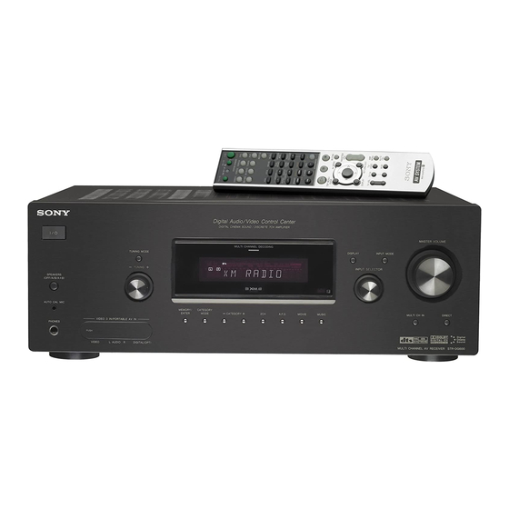
Multi Channel AV
Receiver
Operating Instructions
Owner's Record
The model and serial numbers are located on the rear of the unit. Record the
serial number in the space provided below. Refer to them whenever you call
upon your Sony dealer regarding this product.
Model No.
Serial No.
STR-DG600
©2006 Sony Corporation
Advertisement
Chapters
Table of Contents

Related Manuals for Sony STR-DG600


Summary of Contents for Sony STR-DG600
-
Page 1: Operating Instructions
Owner’s Record The model and serial numbers are located on the rear of the unit. Record the serial number in the space provided below. Refer to them whenever you call upon your Sony dealer regarding this product. Model No. Serial No. -
Page 2: For Customers In The United States
WARNING To reduce the risk of fire or electric shock, do not expose this apparatus to rain or moisture. To prevent fire, do not cover the ventilation of the apparatus with newspapers, table-cloths, curtains, etc. And don’t place lighted candles on the apparatus. -
Page 3: About This Manual
About This Manual • The instructions in this manual are for model STR-DG600. Check your model number by looking at the lower right corner of the front panel. In this manual, models of area code U is used for illustration purposes unless stated otherwise. Any difference in operation is clearly indicated in the text, for example, “Models of area code CA only”. -
Page 4: Table Of Contents
Table of Contents Getting Started Description and location of parts...5 1: Installing speakers ...15 2: Connecting speakers...16 3a: Connecting the audio components...17 3b: Connecting the video components ...22 4: Connecting the antennas...29 5: Preparing the receiver and the remote ...30 6: Selecting the speaker system ...32 7: Calibrating the appropriate settings automatically... -
Page 5: Getting Started
Getting Started Description and location of parts Front panel TUNING MODE – TUNING SPEAKERS (OFF/A/B/A+B) AUTO CAL MIC VIDEO 3 IN/PORTABLE AV IN PHONES VIDEO L AUDIO R DIGITAL(OPT) To remove the cover Press PUSH. When you remove the cover, keep it out of reach from children. - Page 6 Name Function E Display The current status of the selected component or a list of selectable items appears here (page 7). F MULTI Lights up when multi CHANNEL channel audio is decoded DECODING (page 39). lamp G Remote sensor Receives signals from remote commander.
- Page 7 About the indicators on the display SP A DIGITAL EX SP B SLEEP OPT COAX SL S SR SBL SB Name Function A SW Lights up when sub woofer selection is set to “YES” (page 43) and the audio signal is output from the SUB WOOFER jack.
- Page 8 Name Function H MEMORY Lights up when a memory function, such as Preset Memory (page 62), etc., is activated. I A.DIRECT Lights up when ANALOG DIRECT is selected (page 59). J Preset Lights up when using the station receiver to tune in radio stations indicators you have preset.
-
Page 9: Speaker Section
Rear panel DIGITAL OPTICAL VIDEO 1 ANTENNA VIDEO 2 TAPE VIDEO IN TAPE S-VIDEO SA-CD/ COAXIAL AUDIO IN SA-CD/CD MD/TAPE A DIGITAL INPUT/OUTPUT section OPTICAL Connects to a DVD IN/OUT jack player, etc. The COAXIAL jack provides a better COAXIAL IN quality of loud sound jack (page 18, 25, 27). - Page 10 E AUDIO INPUT/OUTPUT section AUDIO IN/ White (L) OUT jack Red (R) MULTI White (L) CHANNEL INPUT jack Red (R) Black PRE OUT White (L) jack Red (R) F ANTENNA section ANTENNA ANTENNA ANTENNA * You can watch the selected input image when you connect the MONITOR OUT jack to a TV monitor (page 24).
-
Page 11: Remote Commander
Remote commander You can use the supplied remote RM-AAP012 to operate the receiver and to control the Sony audio/video components that the remote is assigned to operate. You can also program the remote to control non-Sony audio/video components. For details, see “Programming the remote”... - Page 12 Name Function A AV ?/1 Press to turn on or off the audio/video components that the remote is programmed to operate. If you press ?/1 (B) at the same time, it will turn off the receiver and other components (SYSTEM STANDBY).
- Page 13 Name Function S DISPLAY Press to select information displayed on the TV screen of the TV, VCR, VCD player, LD player, DVD player, CD player, MD deck, Blu-ray disc recorder, hard disc recorder, PSX, or satellite tuner. T Control After pressing AMP MENU buttons (L), TOP MENU/GUIDE (U), or AV MENU (V),...
- Page 14 When you press any of the input buttons, the receiver turns on. The buttons are factory assigned to control Sony components as follows. You can program the remote to control non-Sony components following the steps in “Programming the remote”...
-
Page 15: 1: Installing Speakers
1: Installing speakers This receiver allows you to use a 7.1 channel system (7 speakers and one sub woofer). Enjoying a 5.1/7.1 channel system To fully enjoy theater-like multi channel surround sound requires five speakers (two front speakers, a center speaker, and two surround speakers) and a sub woofer (5.1 channel). -
Page 16: 2: Connecting Speakers
2: Connecting speakers MONITOR VIDEO IN VIDEO IN VIDEO OUT VIDEO IN VIDEO OUT S-VIDEO S-VIDEO S-VIDEO S-VIDEO S-VIDEO AUDIO IN AUDIO IN AUDIO OUT AUDIO IN FRONT MD/TAPE VIDEO 2 VIDEO 1 A Monaural audio cord (not supplied) B Speaker cords (not supplied) AFront speaker A (L) BFront speaker A (R) CCenter speaker... -
Page 17: 3A: Connecting The Audio Components
3a: Connecting the audio components How to hook up your components This section describes how to hook up your components to this receiver. Before you begin, refer to “Component to be connected” below for the pages which describe how to connect each component. -
Page 18: Connecting Components With Digital Audio Input/Output Jacks
Connecting components with digital audio input/output jacks The following illustration shows how to connect a Super Audio CD player/CD player and an MD deck/tape deck. Super Audio CD player/CD player OPTICAL VIDEO 1 VIDEO 2 TAPE TAPE SA-CD/ COAXIAL A Audio cord (not supplied) B Coaxial digital cord (not supplied) C Optical digital cord (not supplied) MD deck/Tape deck... - Page 19 Notes on playing a Super Audio CD disc on a Super Audio CD player • No sound is output when you play a Super Audio CD disc on a Super Audio CD player connected to only the SA-CD/CD COAXIAL IN jack on this receiver. When you play a Super Audio CD disc, connect the player to the MULTI CH IN or SA-CD/CD IN jack.
-
Page 20: Connecting Components With Multi Channel Output Jacks
Connecting components with multi channel output jacks If your DVD or Super Audio CD player is equipped with multi channel output jacks, you can connect it to the MULTI CH IN jacks of this receiver to enjoy multi channel sound. Alternatively, the multi channel input jacks can be used to connect an external multi channel decoder. -
Page 21: Connecting Components With Analog Audio Jacks
Connecting components with analog audio jacks The following illustration shows how to connect a component which has analog jacks such as tape deck, etc. Super Audio CD player/ CD player DIGITAL OPTICAL VIDEO 1 ANTENNA VIDEO 2 TAPE TAPE SA-CD/ COAXIAL SA-CD/CD CD player,... -
Page 22: 3B: Connecting The Video Components
3b: Connecting the video components How to hook up your components This section describes how to hook up your components to this receiver. Before you begin, refer to “Component to be connected” below for the pages which describe how to connect each component. -
Page 23: Converting Video Signals
TV monitor etc., INPUT jack Receiver MONITOR OUT jack Receiver INPUT jack Video component OUTPUT jack Notes • Connect image display components such as a TV monitor or a projector to the MONITOR OUT jack on the receiver. • Turn on the receiver when the video and audio of a playback component are being output to a TV through the receiver. -
Page 24: Tv Monitor
Hooking up a TV monitor The image from a visual component connected to this receiver can be displayed on a TV screen. It is not necessary to connect all the cables. Connect video cords according to the jacks of your components. DIGITAL OPTICAL VIDEO 1... -
Page 25: Connecting Audio
Hooking up a DVD player/DVD recorder The following illustration shows how to connect a DVD player/DVD recorder. It is not necessary to connect all the cables. Connect audio and video cords according to the jacks of your components. 1 Connecting audio DVD player DIGITAL OPTICAL... -
Page 26: Connecting Video
2 Connecting video DIGITAL OPTICAL VIDEO 1 ANTENNA VIDEO 2 TAPE TAPE SA-CD/ COAXIAL SA-CD/CD A S-video cord (not supplied) B Video cord (not supplied) C Component video cord (not supplied) If you connect a DVD recorder • Be sure to change the factory setting of the VIDEO 1 input button on the remote so that you can use the button to control your DVD recorder. -
Page 27: Satellite Tuner
Hooking up a satellite tuner The following illustration shows how to connect a satellite tuner. It is not necessary to connect all the cables. Connect audio and video cords according to the jacks of your components. DIGITAL OPTICAL VIDEO 1 ANTENNA VIDEO 2 TAPE... -
Page 28: Vcr
Hooking up components with analog video and audio jack The following illustration shows how to connect a component which has analog jacks such as a VCR, etc. DIGITAL OPTICAL VIDEO 1 ANTENNA VIDEO 2 TAPE TAPE SA-CD/ COAXIAL SA-CD/CD To the VIDEO 3 IN/PORTABLE AV IN jacks Camcorder/ video game A Audio/video cord (not supplied) -
Page 29: 4: Connecting The Antennas
4: Connecting the antennas Connect the supplied AM loop antenna and FM wire antenna. FM wire antenna (supplied) DIGITAL OPTICAL VIDEO 1 ANTENNA VIDEO 2 TAPE TAPE SA-CD/ COAXIAL * The shape of the connector varies depending on the area code of this receiver. Notes •... -
Page 30: 5: Preparing The Receiver And The Remote
5: Preparing the receiver and the remote Connecting the AC power cord Connect the AC power cord to a wall outlet. AC power cord AC OUTLET – ND BACK – – NT A FRONT B To the wall outlet * The configuration, shape and number of AC outlets will vary according to the area code of the receiver you purchased. -
Page 31: Inserting Batteries Into The Remote
Press MEMORY/ENTER. After “CLEARING” appears on the display for a while, “CLEARED” appears. The following items are reset to their factory settings. • All settings in the LEVEL, EQ, SUR, TUNER, AUDIO, VIDEO and SYSTEM menus. • The sound field memorized for each input and preset station. -
Page 32: 6: Selecting The Speaker System
6: Selecting the speaker system You can select the front speakers you want to drive. Be sure to use the buttons on the receiver for this operation. MULTI CHANNEL DECODING TUNING MODE – TUNING SPEAKERS (OFF/A/B/A+B) AUTO CAL MIC MEMORY/ CATEGORY ENTER MODE... -
Page 33: Performing Auto Calibration
Tips • You can also fix the optimizer microphone to a tripod (not supplied) and place the tripod at your listening position. • Be sure to remove any obstacles in the path between the optimizer microphone and the speakers. • When you face the speaker towards the optimizer microphone, you will get a more accurate measurement. -
Page 34: Error Codes
Error and warning codes Error codes When an error is detected during Auto Calibration, an error code will appear on the display cyclically after each measurement process as follows: Error code t blank display t (error code t blank display) t PUSH t blank display t ENTER Appears when there are more than one error code. - Page 35 Warning code and solution Warning Explanation Solution code WARN. 40 The environment Make sure the is noisy. environment is quiet during Auto Calibration. WARN. 60 The front speaker Reposition your balance is out of front speakers. range. WARN. 62 The center speaker Reposition your level is out of center speaker.
-
Page 36: 8: Adjusting The Speaker Levels And Balance (Test Tone)
8: Adjusting the speaker levels and balance (TEST TONE) You can adjust the speaker levels and balance while listening to the test tone from your listening position. The receiver employs a test tone with a frequency centered at 800 Hz. MUTING TOP MENU/ GUIDE... -
Page 37: Playback
Playback Selecting a component TV ?/1 AV ?/1 RM SET UP SYSTEM STANDBY SLEEP VIDEO1 VIDEO2 VIDEO3 MD/TAPE SA-CD/CD TUNER MULTI CH A.F.D. MOVIE MUSIC DUAL CATEGORY CATEGORY MONO MODE AUDIO JUMP/ PRESET/ ANGLE TUNING TIME CH/D.SKIP MEMORY SUBTITLE ENTER >... -
Page 38: Listening/Watching A Component
VIDEO MENU AUTO WIDE Notes • The operation is described for a Sony Super Audio CD player. • Refer to the operating instructions supplied with the Super Audio CD player or CD player. Tips • You can select the sound field to suit the music. -
Page 39: Watching A Dvd
Watching a DVD TV ?/1 AV ?/1 RM SET UP SYSTEM STANDBY SLEEP VIDEO1 VIDEO2 VIDEO3 MD/TAPE SA-CD/CD TUNER MULTI CH A.F.D. MOVIE MUSIC DUAL CATEGORY CATEGORY MONO MODE AUDIO ANGLE JUMP/ PRESET/ TUNING TIME CH/D.SKIP SPEAKERS MEMORY SUBTITLE ENTER (OFF/A/B/A+B) >... -
Page 40: Amplifier Operations
Amplifier Operations Navigating through menus By using the amplifier menus, you can make various adjustments to customize the receiver. TOP MENU/ GUIDE AV MENU DISPLAY RETURN/EXIT TV VOL TV CH VIDEO WIDE Press AMP MENU. “1-LEVEL” appears on the display. Press control button V/v repeatedly to select the menu you want. -
Page 41: Overview Of The Menus
Overview of the menus The following options are available in each menu. For details on navigating through menus, see page 40. Menu Parameters [Display] [Display] LEVEL (44) Test tone [T. TONE] [1-LEVEL] Front speaker balance [FRT BAL] Center speaker level [CNT LVL] Surround left speaker level [SL LVL]... - Page 42 Menu Parameters [Display] [Display] TUNER (47) FM station receiving mode [4-TUNER] [FM MODE] Naming preset stations [NAME IN] AUDIO (48) Digital audio input decoding [5-AUDIO] priority [DEC. PRI.] Digital broadcast language selection A/V Sync Naming inputs VIDEO (49) Component video assign [6-VIDEO] [COMP.
- Page 43 Menu Parameters [Display] [Display] SYSTEM (49) Sub woofer [7-SYSTEM] [SW SPK] Front speakers [FRT SPK] Center speakers [CNT SPK] Surround speakers [SUR SPK] Surround back speakers [SB SPK] Front speaker distance [FRT DIST.] Center speaker distance [CNT DIST.] Surround left speaker distance [SL DIST.] Surround right speaker distance...
-
Page 44: Adjusting The Level (Level Menu)
Adjusting the level (LEVEL menu) You can use the LEVEL menu to adjust the balance and level of each speaker. These settings are applied to all sound fields. Select “1-LEVEL” in the amplifier menus. For details on adjusting the parameters, see “Navigating through menus”... -
Page 45: Adjusting The Equalizer (Eq Menu)
Adjusting the equalizer (EQ menu) You can use the EQ menu to adjust the tonal quality (bass/treble level) of the front speakers. These settings are applied to all sound fields. Select “2-EQ” in the amplifier menus. For details on adjusting the parameters, see “Navigating through menus”... -
Page 46: Using The Surround Back Decoding Mode
Using the surround back decoding mode (SUR BACK DECODING) By decoding the surround back signal of DVD software (etc.) recorded in Dolby Digital Surround EX, DTS-ES Matrix, DTS-ES Discrete 6.1, etc., format, you can enjoy the surround sound intended by the filmmakers. Select the surround back decoding mode using “SB DEC”... -
Page 47: Settings For The Tuner (Tuner Menu)
Notes • There may be no sound from the surround back speaker in Dolby Digital EX mode. Some discs have no Dolby Digital Surround EX flag even though the packages have Dolby Digital EX logos. In this case, select “SB ON”. •... -
Page 48: Settings For The Audio (Audio Menu)
Settings for the audio (AUDIO menu) You can use the AUDIO menu to make settings for the audio to suit your preference. Select “5-AUDIO” in the amplifier menus. For details on adjusting the parameters, see “Navigating through menus” (page 40) and “Overview of the menus”... -
Page 49: Settings For The Video (Video Menu)
Settings for the video (VIDEO menu) You can use the VIDEO menu to reassign the component video input to another input and to name inputs. Select “6-VIDEO” in the amplifier menus. For details on adjusting the parameters, see “Navigating through menus” (page 40) and “Overview of the menus”... - Page 50 • SMALL If the sound is distorted, or you feel a lack of surround effects when using multi channel surround sound, select “SMALL” to activate the bass redirection circuitry and output the front channel bass frequencies from the sub woofer. When the front speakers are set to “SMALL”, the center, surround, and surround back speakers are also automatically set to “SMALL”...
-
Page 51: Speaker Distance
The “LARGE” and “SMALL” settings for each speaker determine whether the internal sound processor will cut the bass signal from that channel. When the bass is cut from a channel, the bass redirection circuitry sends the corresponding bass frequencies to the sub woofer or other “LARGE” speakers. -
Page 52: Surround Speaker Position
x SBL DIST. (Surround back left speaker distance) Lets you set the distance from your listening position to the surround back left speaker. Surround back left speaker distance should be set from a distance equal to the front speaker distance (A) to a distance 15 feet closer to your listening position (E). -
Page 53: Calibrating The Appropriate Settings Automatically (A. Cal Menu)
Surround speaker position is designed specifically for implementation of the Cinema Studio EX modes. For other sound fields, speaker position is not so critical. Those sound fields were designed under the premise that the surround speakers would be located behind the listening position, but presentation remains fairly consistent even with the surround speakers positioned at a rather wide angle. -
Page 54: Enjoying Surround Sound
Enjoying Surround Sound Enjoying Dolby Digital and DTS Surround sound (AUTO FORMAT DIRECT) The Auto Format Direct (A.F.D.) mode allows you to listen to higher fidelity sound and select the decoding mode for listening to a 2 channel stereo sound as multi channel sound. A.F.D. - Page 55 Types of A.F.D. mode Decoding A.F.D. mode mode [Display] (Detecting A.F.D. AUTO automatically) [A.F.D. AUTO] Dolby Pro Logic PRO LOGIC [DOLBY PL] Dolby Pro Logic PRO LOGIC II MOVIE [PLII MV] PRO LOGIC II MUSIC [PLII MS] PRO LOGIC II GAME [PLII GM] Dolby Pro Logic PRO LOGIC IIx MOVIE...
-
Page 56: Selecting A Pre-Programmed Sound Field
If you connect a sub woofer This receiver will generate a low frequency signal for output to the sub woofer when there is no LFE signal, which is a low-pass sound effect output from a sub woofer to a 2 channel signal. - Page 57 [HP MULTI] HEADPHONE THEATER DCS [HP THEA] Effect Reproduces the sound characteristics of the Sony Pictures Entertainment “Cary Grant Theater” cinema production studio. This is a standard mode, great for watching almost any type of movie. Reproduces the sound characteristics of the Sony Pictures Entertainment “Kim Novak Theater”...
- Page 58 Sound fields with D C S mark use DCS technology. DCS is a unique sound reproduction technology for home theater developed by Sony, in cooperation with Sony Pictures Entertainment, for enjoying the exciting and powerful sound of movie theaters at home. With this “Digital Cinema Sound” developed...
-
Page 59: Using Only The Front Speakers (2Ch Stereo)
Using only the front speakers (2CH STEREO) In this mode, the receiver outputs the sound from the front left/right speakers only. There is no sound from the sub woofer. Standard 2 channel stereo sources completely bypass the sound field processing and multi channel surround formats are downmixed to 2 channel. -
Page 60: Resetting Sound Fields To The Initial Settings
Resetting sound fields to the initial settings Be sure to use the buttons on the receiver for this operation. MULTI CHANNEL DECODING TUNING MODE – TUNING SPEAKERS (OFF/A/B/A+B) AUTO CAL MIC MEMORY/ CATEGORY ENTER MODE CATEGORY A.F.D. MOVIE VIDEO 3 IN/PORTABLE AV IN PHONES VIDEO L AUDIO R... -
Page 61: Automatic Tuning
Automatic tuning VIDEO1 VIDEO2 VIDEO3 MD/TAPE SA-CD/CD TUNER MULTI CH A.F.D. MOVIE MUSIC DUAL CATEGORY CATEGORY MONO MODE JUMP/ PRESET/ AUDIO ANGLE TIME CH/D.SKIP TUNING MEMORY SUBTITLE ENTER > Press TUNER repeatedly to select the FM or AM band. Press TUNING + or TUNING –. Press TUNING + to scan from low to high;... -
Page 62: Presetting Radio Stations
Presetting radio stations You can preset up to 30 FM stations and 30 AM stations. Then you can easily tune in the stations you often listen to. Presetting radio stations VIDEO1 VIDEO2 VIDEO3 MD/TAPE SA-CD/CD TUNER A.F.D. MOVIE DUAL Numeric CATEGORY MONO buttons... -
Page 63: Tuning To Preset Stations
Tuning to preset stations MD/TAPE SA-CD/CD TUNER MULTI CH A.F.D. MOVIE MUSIC DUAL CATEGORY CATEGORY MONO MODE Numeric AUDIO ANGLE JUMP/ PRESET/ buttons TIME CH/D.SKIP TUNING MEMORY SUBTITLE ENTER > 0/10 >10/11 D.TUNING DISC CLEAR SEARCH MODE Press TUNER repeatedly to select the FM or AM band. -
Page 64: Listening To The Xm Radio
Press the control button or control button b to enter the parameter. The cursor flashes and you can select a character. Follow the procedure given in “To create an index name” below. To return to the previous display Press control button B. To create an index name Use control button V/v/B/b to create an index name. -
Page 65: Select Channel
XM will send a signal from the satellites to activate the full channel lineup. Activation normally takes 10 to 15 minutes, but during peak busy periods, you may need to keep your player on for up to an hour. When you can access the full channel lineup on your player, you’re done. -
Page 66: Display Description
Display Description 2 (two) 5 (five) 6 (six) 8 (eight) 0 (zero) Receiving XM Radio broadcasts VIDEO1 VIDEO2 VIDEO3 MD/TAPE SA-CD/CD TUNER MULTI CH A.F.D. MOVIE MUSIC DUAL CATEGORY CATEGORY MONO AUDIO ANGLE JUMP/ PRESET/ TIME CH/D.SKIP TUNING MEMORY SUBTITLE ENTER >... -
Page 67: Select The Channel
Selecting channels from a category (CATEGORY TUNING) You can select a channel from one category or all the categories by changing the category mode. MD/TAPE SA-CD/CD TUNER MULTI CH A.F.D. MOVIE MUSIC DUAL CATEGORY CATEGORY MONO MODE AUDIO ANGLE JUMP/ PRESET/ TUNING TIME... -
Page 68: Presetting Xm Radio Stations
Displaying the XM-RADIO information on the front panel display MULTI CHANNEL DECODING TUNING MODE – TUNING SPEAKERS (OFF/A/B/A+B) AUTO CAL MIC MEMORY/ CATEGORY ENTER MODE CATEGORY A.F.D. MOVIE VIDEO 3 IN/PORTABLE AV IN PHONES VIDEO L AUDIO R DIGITAL(OPT) Press DISPLAY on the receiver repeatedly. - Page 69 Press ALT and then press the numeric buttons to enter the preset number. You can also select the number by pressing PRESET + or PRESET –. You can also turn TUNING +/– on the receiver. Preset numbers from 1 to 30 are available, and channel 1 is preset for all the preset numbers when you purchase the receiver.
- Page 70 XM Radio messages list Message Explanation appears ANTENNA The XM antenna is not connected or transmission is not being received properly. UPDATING The encryption code is being updated. NO SIGNL The signal is too weak. LOADING The audio channel or information is being acquired.
-
Page 71: Other Operations
Other Operations Switching the audio input mode (INPUT MODE) You can select the audio input mode by setting the audio input mode when you connect components to both digital and analog audio input jacks on the receiver. Turn INPUT SELECTOR on the receiver to select the input. -
Page 72: Naming Inputs
Press control button V/v repeatedly to select the input you want the component video input selected in step 6 to be reassigned to (for example, VIDEO 1). In this case, select “DVD–VD1”. When you press VIDEO 1, the image from the component connected to the VIDEO 1 jacks will be a component image. -
Page 73: Changing The Display
Changing the display You can check the sound field, etc., by changing the information on the display. Be sure to use the buttons on the receiver for this operation. Press DISPLAY repeatedly. Each time you press the button, the display changes cyclically as follows. -
Page 74: Recording Using The Receiver
Recording using the receiver Recording onto a MiniDisc or audio tape You can record onto a MiniDisc or audio tape using the receiver. See the operating instructions supplied with your MD deck or tape deck. Press one of the input buttons to select the playback component. -
Page 75: Using The Remote
Furthermore, you can also program the remote for Sony components that the remote is unable to control. Note that the remote can only control components that accept infrared wireless control signals. - Page 76 Use the numeric codes in the tables below to control non-Sony components and also Sony components that the remote is normally unable to control. Since the remote signal that a component accepts differs depending on the...
- Page 77 TELEFUNKEN 751, 752 TOSHIBA 747, 755, 756 ZENITH * If an AIWA VCR does not work even though you enter the code for AIWA, enter the code for Sony instead. To control a DVD player Maker Code(s) SONY 401, 402, 403...
-
Page 78: Additional Information
To control a satellite tuner or cable box Maker Code(s) SONY 801, 802, 803, 804 JERROLD/G.I. 806, 807, 808, 809, 810, 811, 812, 813, PANASONIC 805, 819 S. ATLANTA 815, 816, 817 To control a tuner Maker Code(s) SONY 002, 003, 004, 005... - Page 79 x Dolby Pro Logic II This technology converts 2ch stereo recorded audio into 5.1ch for playback. There is a MOVIE mode for movies and MUSIC mode for stereo sources such as music. Old movies encoded in the traditional stereo format can be enhanced with 5.1ch surround sound.
-
Page 80: Precautions
Do not use any type of abrasive pad, scouring powder, or solvent, such as alcohol or benzine. If you have any questions or problems concerning your receiver, please consult your nearest Sony dealer. -
Page 81: Troubleshooting
Troubleshooting If you experience any of the following difficulties while using the receiver, use this troubleshooting guide to help you remedy the problem. There is no sound, no matter which component is selected, or only a very low-level sound is heard. •... - Page 82 There is severe hum or noise. • Check that the speakers and components are connected securely. • Check that the connecting cords are away from a transformer or motor, and at least 10 feet away from a TV set or fluorescent light.
-
Page 83: Remote Control
You can check the condition of the system by the message. Refer to the following table to solve the problem. If any problem persists, consult your nearest Sony dealer. If an error message appears while you perform Auto Calibration, see “Error and warning codes”... -
Page 84: Specifications
If the problem persist Consult your nearest Sony dealer. Note that if service personnel changes some parts during repair, these parts may be retained. Reference sections for clearing the receiver’s memory... - Page 85 Frequency response Analog 10 Hz – 70 kHz +0.5/–2 dB (with sound field and equalizer bypassed) Inputs Analog Sensitivity: 500 mV/ 50 kohms : 96 dB (A, 500 mV Digital (Coaxial) Impedance: 75 ohms S/N: 100 dB (A, 20 kHz LPF) Digital ( Optical S/N: 100 dB...
- Page 86 Supplied accessories FM wire antenna (1) AM loop antenna (1) Remote commander RM-AAP012 (1) R6 (size-AA) batteries (2) Optimizer microphone ECM-AC2 (1) For details on the area code of the component you are using, see page 3. Design and specifications are subject to change without notice.
-
Page 87: Index
Index Numerics 2 channel 59 2CH STEREO 59 5.1 channel 15 7.1 channel 15 AUTO CALIBRATION 32 AUTO FORMAT DIRECT (A.F.D.) 54 CD player connecting 17 playback 38 COMPONENT VIDEO ASSIGN 71 Digital Cinema Sound (DCS) 58 Dolby Digital 78 DTS 79 DVD player hooking up 22... - Page 88 Sony Corporation Printed in Malaysia...
Need help?
Do you have a question about the STR-DG600 and is the answer not in the manual?
Questions and answers