Sony STR-DG500 Service Manual
Multi channel av receiver
Hide thumbs
Also See for STR-DG500:
- Operating instructions manual (76 pages) ,
- Quick setup manual (2 pages) ,
- Specifications (2 pages)
Table of Contents
Advertisement
Quick Links
All manuals and user guides at all-guides.com
STR-DG500/DG600
SERVICE MANUAL
Ver. 1.0 2006. 02
Manufactured under license from Dolby Laboratories.
"Dolby", "Pro Logic", "Surround EX", and the double-D
symbol are trademarks of Dolby Laboratories.
"DTS", "DTS-ES", "Neo:6", and "DTS 96/24" are
trademarks of Digital Theater Systems, Inc.
AUDIO POWER SPECIFICATIONS
POWER OUTPUT AND TOTAL HARMONIC
DISTORTION:
(Models of area code US only)
With 8 ohm loads, both channels driven, from
20 – 20,000 Hz; rated 100 watts per channel
minimum RMS power, with no more than
0.09 % total harmonic distortion from 250
milliwatts to rated output.
Amplifier section
Power Output
Models of area code US, CND
1)
Stereo Power Output
, Reference Power Output
8 ohms 20 Hz – 20 kHz, THD 0.09 %
100 W + 100 W, 110 W/ch
8 ohms 1 kHz, THD 0.7 %
110 W + 110 W, 120 W/ch
8 ohms 1 kHz, THD 10 %
125 W + 125 W, 150 W/ch
Models of area code AEP, UK, E2, TW, AUS
1)
Stereo Power Output
, Reference Power Output
8 ohms 20 Hz – 20 kHz, THD 0.09 %
85 W + 85 W, 110 W/ch
8 ohms 1 kHz, THD 0.7 %
100 W + 100 W, 120 W/ch
8 ohms 1 kHz, THD 10 %
125 W + 125 W, 150 W/ch
Sony Corporation
9-887-127-01
2006B04-1
Home Audio Division
© 2006. 02
Published by Sony Techno Create Corporation
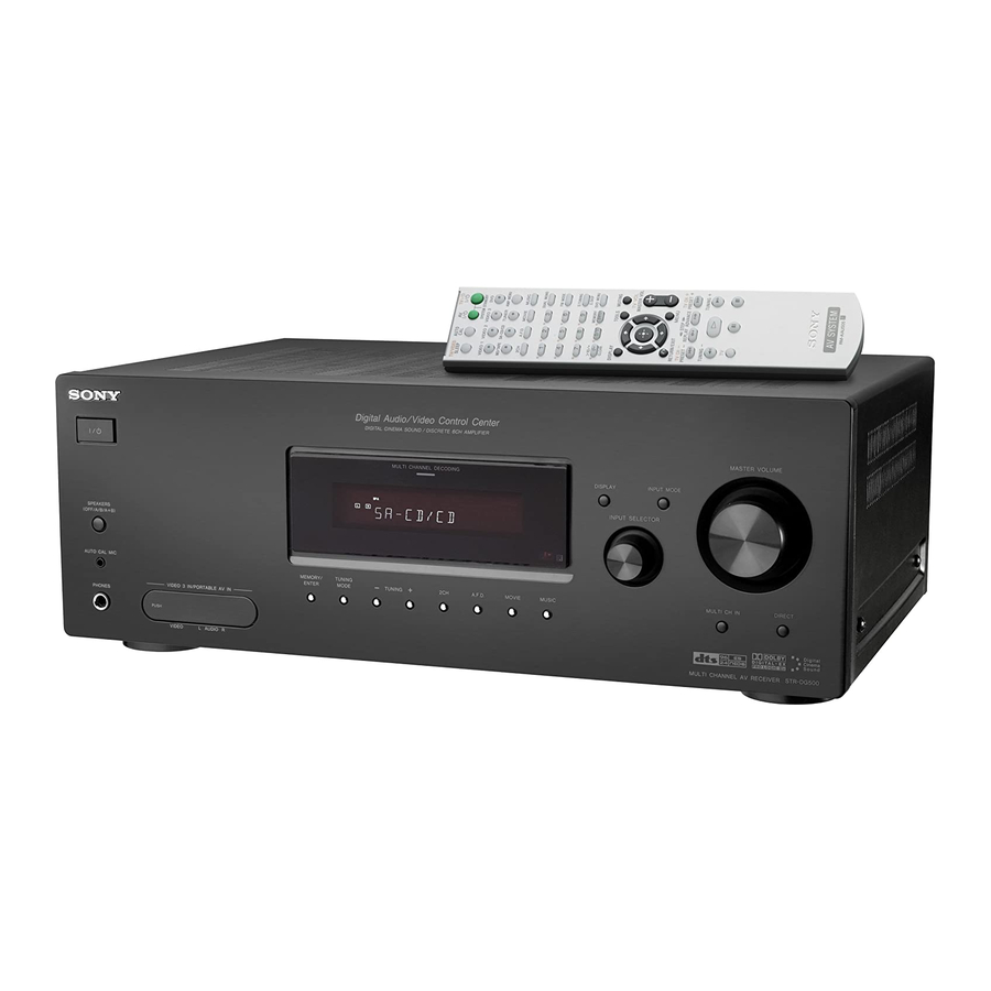
Photo: STR-DG600: Silver type
SPECIFICATIONS
1) Measured under the following conditions:
Area code
US, CND
AEP, UK, KR
1) 2)
E2, AUS
TW
2) Reference power output for front, center, surround
3) Measured under the following conditions:
Area code
1) 2)
KR
Canadian Model
Australian Model
Models of area code KR
1)
Stereo Power Output
, Reference Power Output
8 ohms 20 Hz – 20 kHz, THD 0.09 %
1)
85 W + 85 W
70 W + 70 W
3)
8 ohms 1 kHz, THD 0.7 %
100 W + 100 W
90 W + 90 W
3)
8 ohms 1 kHz, THD 10 %
125 W + 125 W
110 W + 110 W
Power requirements
120 V AC, 60 Hz
230 V AC, 50 Hz
240 V AC, 50 Hz
110 V AC, 60 Hz
and surround back. Depending on the sound field
settings and the source, there may be no sound output.
Power requirements
220 V AC, 50 Hz
MULTI CHANNEL AV RECEIVER
US Model
STR-DG500/DG600
AEP Model
UK Model
E Model
STR-DG500
1) 2)
,
, 110 W/ch
1)
,
, 120 W/ch
1)
,
3)
, 150 W/ch
– Continued on next page –
1
Advertisement
Table of Contents

Related Manuals for Sony STR-DG500


Summary of Contents for Sony STR-DG500
- Page 1 100 W + 100 W, 120 W/ch 8 ohms 1 kHz, THD 10 % 125 W + 125 W, 150 W/ch MULTI CHANNEL AV RECEIVER Sony Corporation 9-887-127-01 2006B04-1 Home Audio Division © 2006. 02 Published by Sony Techno Create Corporation...
- Page 2 All manuals and user guides at all-guides.com STR-DG500/DG600 Frequency response Video section Analog 10 Hz – 70 kHz Inputs/Outputs +0.5/–2 dB (with sound Video: 1 Vp-p, 75 ohms field and tone (DG500) or S-video (DG600): Y: 1 Vp-p, 75 ohms equalizer (DG600) bypassed) C: 0.286 Vp-p, 75 ohms...
- Page 3 REPLACE THESE COMPONENTS WITH SONY PARTS WHOSE NE REMPLACER CES COMPOSANTS QUE PAR DES PIÈCES PART NUMBERS APPEAR AS SHOWN IN THIS MANUAL OR SONY DONT LES NUMÉROS SONT DONNÉS DANS CE MANUEL IN SUPPLEMENTS PUBLISHED BY SONY. OU DANS LES SUPPLÉMENTS PUBLIÉS PAR SONY.
-
Page 4: Table Of Contents
All manuals and user guides at all-guides.com STR-DG500/DG600 TABLE OF CONTENTS 1. GENERAL Description and location of parts (STR-DG500) ....5 Description and location of parts (STR-DG600) ....7 2. DISASSEMBLY 2-1. Case ................... 10 2-2. Front Panel Section ............11 2-3. -
Page 5: General
All manuals and user guides at all-guides.com STR-DG500/DG600 SECTION 1 GENERAL This section is extracted from instruction manual. STR-DG500: Name Function Name Function Getting Started F DISPLAY R VIDEO 3 IN/ Press to select information To connect a camcorder or... - Page 6 Rear panel OUTPUT section You can use the supplied remote RM-AAU005 COMPONENT Connects to a DVD Green to operate the receiver and to control the Sony VIDEO player, TV, or a INPUT/ satellite tuner. You audio/video components that the remote is...
-
Page 7: Description And Location Of Parts (Str-Dg600)
All manuals and user guides at all-guides.com STR-DG500/DG600 STR-DG600: Name Function Name Function Getting Started E Display Q CATEGORY +/– Press to select a category The current status of the selected component or a (page 67). list of selectable items... - Page 8 TV, Blu-ray disc to operate the receiver and to control the Sony operate. recorder, hard disc recorder, audio/video components that the remote is If you press ?/1 (B) at the PSX, or satellite tuner.
- Page 9 Blu-ray disc recorder, are factory assigned to control hard disc recorder, or PSX. PSX, or satellite tuner. Sony components as follows. ANGLE Press to select the viewing – fast forward/rewind of the You can program the remote...
-
Page 10: Disassembly
All manuals and user guides at all-guides.com STR-DG500/DG600 SECTION 2 DISASSEMBLY Note : This set can be disassemble according to the following sequence. 2-1. CASE (Page 10) 2-2. FRONT PANEL SECTION 2-3. BACK PANEL SECTION (Page 11) (Page 11) 2-6. STANDBY BOARD 2-4. -
Page 11: Front Panel Section
All manuals and user guides at all-guides.com STR-DG500/DG600 2-2. FRONT PANEL SECTION 6 two screws (+BVTP 3 × 8) 4 CNP202 (3P) 2 CNP791 (4P) 1 CNP2000 (4P) 5 CNP503 (3P) 8 front panel section 3 CNS505 (23 core) 7 five screws (+BVTP 3 ×... -
Page 12: Digital Board
All manuals and user guides at all-guides.com STR-DG500/DG600 2-4. DIGITAL BOARD 2 CNP503 (5P) 1 CNP505 (10P) 5 DIGITAL board 3 CNP504 (7P) 4 screw (+BVTP 3 × 8) 2-5. MAIN BOARD SECTION 7 screw 4 CNP802 (5P) (+BV3 (3 -CR) ) -
Page 13: Standby Board
All manuals and user guides at all-guides.com STR-DG500/DG600 2-6. STANDBY BOARD 3 screw 4 STANDBY board (+BVTP 3 × 8) 1 CNP902 (2P) 2 CNP804 (3P) 2-7. SB AMP BOARD (DG600) 3 two screws (+BVTP 3 × 8) 4 three screws... -
Page 14: Test Mode
When this test is activated, all segments light on at the same power. time, then each segment lights on one after another. Either the message “REST 13” (STR-DG500) or “REST 14” * Procedure: (STR-DG600) appears. While depressing the [TUNING MODE] and the [DISPLAY] but-... -
Page 15: Diagrams
All manuals and user guides at all-guides.com STR-DG500/DG600 SECTION 4 DIAGRAMS 4-1. BLOCK DIAGRAM — TUNER/AUDIO SECTION — VIDEO 3 IN/ DG600 PORTABLE AV IN VIDEO 1 VIDEO 2 SA-CD/CD MD/TAPE MD/TAPE DVD AUDIO AUDIO AUDIO OUT AUDIO IN AUDIO IN –7V... -
Page 16: Block Diagram - Digital Section
All manuals and user guides at all-guides.com STR-DG500/DG600 4-2. BLOCK DIAGRAM — DIGITAL SECTION — 8CH DAC DG600 DG500 IC1401 IC1501 IC1452 IC1403 VOUT5 L OUT DOUT DATA3 L IN AUDIO L-IN SDI1 SD01 VOUT6 SD02 24 R-CH TUNER/ SD03 25... -
Page 17: Block Diagram - Video Section
All manuals and user guides at all-guides.com STR-DG500/DG600 4-3. BLOCK DIAGRAM — VIDEO SECTION — DG600 Y/C SEPARATION COMPONENT VIDEO SELECT IC370 BUFFER IC304 IC372 V+1,+2 VIDEO AMP +5V-3 J301 (1/2) Q327 6dB AMP J301 (2/2) YOUT CH1 IN2 Y PROCESS CHI OUT 75Ω... -
Page 18: Block Diagram - Xm Section (Dg600)
All manuals and user guides at all-guides.com STR-DG500/DG600 4-4. BLOCK DIAGRAM — XM SECTION (DG600) — XM DIGITAL TRANSCEIVER IC102 SCTXOUT XM MIXMI KEY/DISPLAY SCRXIN XM MIXMO SECTION COMMSEL 18 COMRXP (Page 19) BUFFER 19 COMRXT XM64FS IC103 XMDATA 23 COMTXP J101 –D... -
Page 19: Block Diagram - Key/Display Section
All manuals and user guides at all-guides.com STR-DG500/DG600 4-5. BLOCK DIAGRAM — KEY/DISPLAY SECTION — FL DISPLAY DRIVER SYSTEM IC100 CONTROL IC1101 (4/5) MIC AMP IC2000 SEG1 FL101 D2014 FL LAT 9 STB J2000 SEG16 VACUUM 38 ADCC BUFFER 7 DIN... -
Page 20: Block Diagram - Power Section
All manuals and user guides at all-guides.com STR-DG500/DG600 4-6. BLOCK DIAGRAM — POWER SECTION — DG600 J310 SURROUND PRE OUT R-CH J791 PHONES R-CH PRE DRIVER IC701 TM600(DG600) TM602(DG500) +VOUT2 IN 2 L-CH DRIVE -VOUT2 DRIVE POWER AMP RELAY Q701-704... -
Page 21: Circuit Boards Location
All manuals and user guides at all-guides.com STR-DG500/DG600 4-7. CIRCUIT BOARDS LOCATION THIS NOTE IS COMMON FOR PRINTED WIRING BOARDS AND SCHEMATIC DIAGRAMS. (In addition to this, the necessary note is printed in each block.) for schematic diagram: for printed wiring boards: •... -
Page 22: Printed Wiring Boards - Main Section
All manuals and user guides at all-guides.com STR-DG500/DG600 4-8. PRINTED WIRING BOARDS — MAIN SECTION — • Refer to page 21 for Circuit Boards Location. : Uses unleaded solder. TM601 J401 J400 J402 J403 J404 J309 J310 CC17 R436 R321... -
Page 23: Schematic Diagram - Main Section (1/3)
All manuals and user guides at all-guides.com STR-DG500/DG600 4-9. SCHEMATIC DIAGRAM — MAIN SECTION (1/3) — CN720 J402 J400 WP100 (Page 34) R451 R401 CNP501 CC52 R452 CC02 R402 C702 C464 CC59 R459 C495 C497 C490 C485 C459 C762 CC09... -
Page 24: Schematic Diagram - Main Section (2/3)
All manuals and user guides at all-guides.com STR-DG500/DG600 4-10. SCHEMATIC DIAGRAM — MAIN SECTION (2/3) — • Refer to page 48 for IC Block Diagrams. IC B/D CN792 CNP791 C790 R719 C720 IC701 J791 R745 C717 R794 R714 Q701 R740... -
Page 25: Schematic Diagram - Main Section (3/3)
All manuals and user guides at all-guides.com STR-DG500/DG600 4-11. SCHEMATIC DIAGRAM — MAIN SECTION (3/3) — (Page 23) (Page 24) J309 RY560 R470 R468 R469 D802 Q560 C400 Q801 R803 IC402 C805 CNP801 R533 R532 D560 C471 C803 C822 C801... -
Page 26: Printed Wiring Board - Digital Section (1/2)
All manuals and user guides at all-guides.com STR-DG500/DG600 4-12. PRINTED WIRING BOARD — DIGITAL SECTION (1/2) — • Refer to page 21 for Circuit Boards Location. : Uses unleaded solder. C1913 JR1202 C1251 C1253 C1316 C1105 R1016 C1141 R1014 R1012... -
Page 27: Printed Wiring Board - Digital Section (2/2)
All manuals and user guides at all-guides.com STR-DG500/DG600 4-13. PRINTED WIRING BOARD — DIGITAL SECTION (2/2) — • Refer to page 21 for Circuit Boards Location. : Uses unleaded solder. (Page 36) (Page 45) (Page 22) (Page JR1019 CNS508 IC1902... -
Page 28: Schematic Diagram - Digital Section (1/5)
All manuals and user guides at all-guides.com STR-DG500/DG600 4-14. SCHEMATIC DIAGRAM — DIGITAL SECTION (1/5) — • Refer to page 47 for Waveforms and page 48 for IC Block Diagrams. CNS508 JR1202 C1251 R1261 R1260 C1252 C1253 R1252 R1251 IC1071... -
Page 29: Schematic Diagram - Digital Section (2/5)
All manuals and user guides at all-guides.com STR-DG500/DG600 4-15. SCHEMATIC DIAGRAM — DIGITAL SECTION (2/5) — • Refer to page 47 for Waveforms and page 54 for IC Pin Descriptions. (Page 28) C1520 (Page 31) FB1502 C1515 C1516 C1517 IC1502... -
Page 30: Schematic Diagram - Digital Section (3/5)
All manuals and user guides at all-guides.com STR-DG500/DG600 4-16. SCHEMATIC DIAGRAM — DIGITAL SECTION (3/5) — • Refer to page 50 for IC Block Diagrams. (Page 28) (Page 29) C1403 IC B/D C1404 IC1401 C1450 R1474 (Page 32) R1402 FB1452... -
Page 31: Schematic Diagram - Digital Section (4/5)
All manuals and user guides at all-guides.com STR-DG500/DG600 4-17. SCHEMATIC DIAGRAM — DIGITAL SECTION (4/5) — • Refer to page 51 for IC Block Diagrams. C2218 IC B/D FB2034 C2216 R1016 CNS509 R1015 R1130 R1014 R1013 R1012 R1011 R1010 C1601... -
Page 32: Schematic Diagram - Digital Section (5/5)
All manuals and user guides at all-guides.com STR-DG500/DG600 4-18. SCHEMATIC DIAGRAM — DIGITAL SECTION (5/5) — • Refer to page 47 for Waveforms and page 56 for IC Pin Descriptions. (Page 31) CNS505 (Page 28) R1187 FB1101 R1201 R1179 R1180... -
Page 33: Printed Wiring Boards - Center/Surround Back Speaker Section
All manuals and user guides at all-guides.com STR-DG500/DG600 4-19. PRINTED WIRING BOARDS — CENTER/SURROUND BACK SPEAKER SECTION — • Refer to page 21 for Circuit Boards Location. : Uses unleaded solder. (Page 22) (Page 22) (Page 22) (Page 22) (Page 22) (Page 22) •... -
Page 34: Schematic Diagram - Center/Surround Back Speaker Section
All manuals and user guides at all-guides.com STR-DG500/DG600 4-20. SCHEMATIC DIAGRAM — CENTER/SURROUND BACK SPEAKER SECTION — • Refer to page 51 for IC Block Diagrams. IC B/D IC2501 CN2570 (Page 24) C2573 R2582 Q2577 R2571 (Page 24) C2578 R2577... -
Page 35: Printed Wiring Board - Front B Speaker Section
All manuals and user guides at all-guides.com STR-DG500/DG600 4-21. PRINTED WIRING BOARD — FRONT B SPEAKER SECTION — 4-22. SCHEMATIC DIAGRAM — FRONT B SPEAKER SECTION — • Refer to page 21 for Circuit Boards Location. : Uses unleaded solder. -
Page 36: Printed Wiring Board - Video Section
All manuals and user guides at all-guides.com STR-DG500/DG600 4-23. PRINTED WIRING BOARD — VIDEO SECTION — • Refer to page 21 for Circuit Boards Location. : Uses unleaded solder. J301 J200 J201 R220 R221 C200 R200 C207 C206 C208 C312... -
Page 37: Schematic Diagram - Video Section
All manuals and user guides at all-guides.com STR-DG500/DG600 4-24. SCHEMATIC DIAGRAM — VIDEO SECTION — • Refer to page 51 for IC Block Diagrams. J298 IC807 CN201 CNP202 CNP203 R299 C220 C223 R219 JW200 C210 C209 C214 C221 JW300 C224... -
Page 38: Printed Wiring Board - S-Video Section
All manuals and user guides at all-guides.com STR-DG500/DG600 4-25. PRINTED WIRING BOARD — S-VIDEO SECTION (DG600) — • Refer to page 21 for Circuit Boards Location. : Uses unleaded solder. • Semiconductor Location Ref. No. Location D251 D252 D253 D254... -
Page 39: Printed Wiring Board - S-Video Up Convert Section (Dg600)
All manuals and user guides at all-guides.com STR-DG500/DG600 4-27. PRINTED WIRING BOARD — S-VIDEO UP CONVERT SECTION (DG600) — • Refer to page 21 for Circuit Boards Location. : Uses unleaded solder. • Semiconductor Location Ref. No. Location IC370 IC372... -
Page 40: Printed Wiring Board - Xm Section (Dg600)
All manuals and user guides at all-guides.com STR-DG500/DG600 4-29. PRINTED WIRING BOARD — XM SECTION (DG600) — • Refer to page 21 for Circuit Boards Location. : Uses unleaded solder. X101 D101 (Page 27) (Page 22) (Page 22) • Semiconductor Location Ref. -
Page 41: Schematic Diagram - Xm Section (Dg600)
All manuals and user guides at all-guides.com STR-DG500/DG600 4-30. SCHEMATIC DIAGRAM — XM SECTION (DG600) — • Refer to page 47 for Waveform and page 53 for IC Block Diagrams. C109 C111 IC103 IC B/D CN101 R101 R102 R103 R152... -
Page 42: Printed Wiring Board - Adcc Section
All manuals and user guides at all-guides.com STR-DG500/DG600 4-31. PRINTED WIRING BOARD — ADCC SECTION — • Refer to page 21 for Circuit Boards Location. : Uses unleaded solder. J2000 D2013 D2014 C2010 R2016 R2015 C2012 C2001 IC2000 (Page 22) -
Page 43: Printed Wiring Boards - Display Section
All manuals and user guides at all-guides.com STR-DG500/DG600 4-33. PRINTED WIRING BOARDS — DISPLAY SECTION — • Refer to page 21 for Circuit Boards Location. : Uses unleaded solder. (Page 2 • Semiconductor Location Ref. No. Location D105 IC100 IC101... -
Page 44: Schematic Diagram - Display Section
All manuals and user guides at all-guides.com STR-DG500/DG600 4-34. SCHEMATIC DIAGRAM — DISPLAY SECTION — C108 C109 R198 R199 FL101 CNS100 L103 C151 R122 C152 L101 C150 R121 C104 D105 C101 R123 R131 Q110 (Page 32) R118 R107 R106 R105... -
Page 45: Printed Wiring Boards - Power Section
All manuals and user guides at all-guides.com STR-DG500/DG600 4-35. PRINTED WIRING BOARDS — POWER SECTION — • Refer to page 21 for Circuit Boards Location. : Uses unleaded solder. (Page 22) (Page 35) C924 • Semiconductor Location Ref. No. Location... -
Page 46: Schematic Diagram - Power Section
All manuals and user guides at all-guides.com STR-DG500/DG600 4-36. SCHEMATIC DIAGRAM — POWER SECTION — T901 (Page 35) (Page 25) CNP804 CNP910 CNP902 F901 CNP907 R810 F902 CNP906 S901 JW903 CNP801 D920 D923 C913 Q901 C915 R903 R902 D901 R811... - Page 47 All manuals and user guides at all-guides.com STR-DG500/DG600 • Waveforms — DIGITAL Board — IC1301 qd (CKOUT) IC1501 qs (MCLK2) 1.1 Vp-p 2.1 Vp-p 13.9 MHz 12.288 MHz 1V/DIV, 50nsec/DIV 1V/DIV, 50nsec/DIV IC1301 qf (BCK) IC1501 qf (SCKOUT) 2.4 Vp-p 2.5 Vp-p...
- Page 48 BIAS CIRCUIT PROTECTOR REG DRIVE DRIVE DRIVE DRIVE 2 3 4 5 6 8 9 10 11 12 13 14 15 IC1301 LC89056W-E (DIGITAL BOARD (1/5) (STR-DG500)) 12 11 10 9 8 7 6 XMODE CKSEL1 CKSEL0 DOSEL1 44 DOSEL0...
- Page 49 All manuals and user guides at all-guides.com STR-DG500/DG600 IC1301 LC890561W (DIGITAL BOARD (1/5) (STR-DG600)) 36 35 32 31 30 29 REGULATOR FS CALCULATION PA,PB DETECT 24 AUDIO C-BIT DETECT 23 EMPHA 22 XIN XSEL 21 XOUT 20 XMCK MODE0 DATA SELECTOR...
- Page 50 All manuals and user guides at all-guides.com STR-DG500/DG600 IC1401 PCM1800E/2K (DIGITAL BOARD (3/5)) 15 14 13 DIGITAL MODULATOR 1/64 SERIAL I/O DECIMATION INTERFACE FILTER & & MODE/FORMAT LOW-CUT CONTROL DIGITAL FILTER MODULATOR SINGLE-END SINGLE-END CLOCK/ DEFERENTIAL REFERENCE DEFERENTIAL TIMING CONTROL RESET/...
- Page 51 All manuals and user guides at all-guides.com STR-DG500/DG600 IC1601 SN74HC595ANSR (DIGITAL BOARD (4/5)) IC1602 SN74HC595ANSR (DIGITAL BOARD (4/5)) SHIFT REGISTER LATCH PARALLEL DATA OUTPUT IC2501 STK350-230 (SB AMP BOARD) (STR-DG600) DRIVER 7 8 9 IC203 NJM2595D (VIDEO BOARD) IC251 NJM2595D (SVIDEO BOARD) (STR-DG600) IC252 NJM2595D (SVIDEO BOARD) (STR-DG600) M.OUT...
- Page 52 All manuals and user guides at all-guides.com STR-DG500/DG600 IC253 LA7213 (SVIDEO BOARD) (STR-DG600) SYNC V-SYNC IC370 TC90A69NG (S VIDEO UP CONVERT BOARD) (STR-DG600) PLL DET IIC BUS 8fsc 4fsc (8fsc) CORING V-ENHANCER CORING PED. DELAY CLIP PEAKING LINE LINE INTERPOLATION...
- Page 53 All manuals and user guides at all-guides.com STR-DG500/DG600 IC102 F2602E-01-TR (XM BOARD) (STR-DG600) HIGH SPEED I2S_DATA 24 VSS DATA PORT 23 COMM_TX_P (HSDP) I2S_SCLK 22 COMM_TX_M 21 VSS I2S_LRCLK 20 VDD 19 COMM_RX_M I2S_OCLK 18 COMM_RX_P COMM ENGINE 17 VDD...
- Page 54 All manuals and user guides at all-guides.com STR-DG500/DG600 • IC Pin Descriptions IC1501 CXD9718BQ (DSP) (DIGITAL BOARD (2/5)) Pin No. Pin Name Pin Description — Ground XRST Reset signal input from SYSTEM CONTROL IC EXTIN Not used (Connect to ground)
- Page 55 All manuals and user guides at all-guides.com STR-DG500/DG600 Pin No. Pin Name Pin Description MOD1 Operation mode signal input (L: 386fs, H: 256fs) (Fixed at H) MOD0 Operation mode signal input (L: single chip mode, H: use prohibited) (Fixed at L)
- Page 56 All manuals and user guides at all-guides.com STR-DG500/DG600 IC1101 MB90488BPF-G-175E1 (SYSTEM CONTROL) (DIGITAL BOARD (5/5)) (STR-DG500) IC1101 MB90488BPF-G-178E1 (SYSTEM CONTROL) (DIGITAL BOARD (5/5)) (STR-DG600) Pin No. Pin Name Pin Description DATAO Serial data line signal input from DIR IC GP9 signal input from DSP IC...
- Page 57 All manuals and user guides at all-guides.com STR-DG500/DG600 Pin No. Pin Name Pin Description RDS data clock signal input (AEP, UK model)/XM digital power control signal output RDS_CLK/XMDPOWER (STR-DG600) RDS_DATA/ RDS data input (AEP, UK model)/XM command control signal output (STR-DG600)
-
Page 58: Exploded Views
All manuals and user guides at all-guides.com STR-DG500/DG600 SECTION 5 EXPLODED VIEWS NOTE: • The mechanical parts with no reference • -XX and -X mean standardized parts, so The components identified by mark 0 or dotted line with mark number in the exploded views are not supplied. -
Page 59: Front Panel Section
All manuals and user guides at all-guides.com STR-DG500/DG600 5-2. FRONT PANEL SECTION not supplied not supplied (POWER board) (ADCC board) not supplied (HEADPHONE board) FL101 not supplied (VIDEO3 board) not supplied (OPT3 board) (DG600) supplied with RV101,103 supplied with RV102 Ref. -
Page 60: Back Panel Section
All manuals and user guides at all-guides.com STR-DG500/DG600 5-3. BACK PANEL SECTION not supplied not supplied (AC SELECT board) (E2 model) not supplied (SPEAKER C/SB board) not supplied (VIDEO board) not supplied (SVIDEO board) (DG600) Ref. No. Part No. Description Remark Ref. -
Page 61: Chassis Section
All manuals and user guides at all-guides.com STR-DG500/DG600 5-4. CHASSIS SECTION not supplied (SB AMP board) not supplied (DG600) (STANDBY board) Q2573 F902 Q2572 not supplied F901 (SPEAKER B board) Q2574 Q654 Q604 Q753 Q653 Q703 Q503 Q603 Q534 Q754... -
Page 62: Electrical Parts List
All manuals and user guides at all-guides.com STR-DG500/DG600 SECTION 6 AC SELECT ADCC DIGITAL ELECTRICAL PARTS LIST NOTE: • Due to standardization, replacements in • SEMICONDUCTORS The components identified by mark 0 or dotted line with mark the parts list may be different from the In each case, u : µ, for example:... - Page 63 All manuals and user guides at all-guides.com STR-DG500/DG600 DIGITAL Ref. No. Part No. Description Remark Ref. No. Part No. Description Remark C1103 1-126-947-11 ELECT 47uF C1316 1-100-566-11 CERAMIC CHIP 0.1uF C1104 1-216-864-11 SHORT CHIP (DG600) C1105 1-216-864-11 SHORT CHIP C1317...
- Page 64 All manuals and user guides at all-guides.com STR-DG500/DG600 DIGITAL Ref. No. Part No. Description Remark Ref. No. Part No. Description Remark C1501 1-100-566-11 CERAMIC CHIP 0.1uF < DIODE > C1502 1-100-566-11 CERAMIC CHIP 0.1uF C1503 1-100-566-11 CERAMIC CHIP 0.1uF D1001...
- Page 65 All manuals and user guides at all-guides.com STR-DG500/DG600 DIGITAL Ref. No. Part No. Description Remark Ref. No. Part No. Description Remark IC1502 6-709-278-01 IC IS61WV6416BLL-12TLI R1065 1-216-809-11 METAL CHIP 1/10W IC1503 8-759-546-74 IC TC7WH157FU(TE12R) R1066 1-216-809-11 METAL CHIP 1/10W IC1601 8-759-268-29 IC SN74HC595ANS...
- Page 66 All manuals and user guides at all-guides.com STR-DG500/DG600 DIGITAL Ref. No. Part No. Description Remark Ref. No. Part No. Description Remark R1150 1-216-809-11 METAL CHIP 1/10W R1304 1-216-809-11 METAL CHIP 1/10W R1151 1-216-809-11 METAL CHIP 1/10W (DG500) R1152 1-216-809-11 METAL CHIP...
- Page 67 All manuals and user guides at all-guides.com STR-DG500/DG600 DIGITAL DISPLAY Ref. No. Part No. Description Remark Ref. No. Part No. Description Remark R1455 1-216-864-11 SHORT CHIP R1804 1-216-809-11 METAL CHIP 1/10W R1456 1-216-821-11 METAL CHIP 1/10W (DG600) (DG600) R1805 1-216-809-11 METAL CHIP...
- Page 68 All manuals and user guides at all-guides.com STR-DG500/DG600 DISPLAY HEADPHONE MAIN Ref. No. Part No. Description Remark Ref. No. Part No. Description Remark C144 1-127-888-11 CERAMIC 0.1uF RV103 1-418-817-11 ENCODER, ROTARY (TUNING +/–) (DG600) C145 1-127-888-11 CERAMIC 0.1uF C146 1-126-795-11 ELECT 10uF <...
- Page 69 All manuals and user guides at all-guides.com STR-DG500/DG600 MAIN Ref. No. Part No. Description Remark Ref. No. Part No. Description Remark C463 1-162-286-31 CERAMIC 220PF C654 1-107-583-11 CERAMIC 0.25PF 500V C464 1-127-888-11 CERAMIC 0.1uF C655 1-102-233-00 CERAMIC 33PF 500V C468...
- Page 70 All manuals and user guides at all-guides.com STR-DG500/DG600 MAIN Ref. No. Part No. Description Remark Ref. No. Part No. Description Remark C811 1-127-888-11 CERAMIC 0.1uF CNP503 1-779-978-11 PIN, CONNECTOR 3P C822 1-126-947-11 ELECT 47uF * CNP801 1-564-104-00 PIN, CONNECTOR (3.96mm PITCH) 3P...
- Page 71 All manuals and user guides at all-guides.com STR-DG500/DG600 MAIN Ref. No. Part No. Description Remark Ref. No. Part No. Description Remark J400 1-774-411-11 JACK, PIN 6P (MD/TAPE OUT,SA-CD/CD IN, Q793 8-729-119-78 TRANSISTOR 2SC2785-HFE AUX IN) (DG600) Q795 8-729-042-09 TRANSISTOR 2SA1038S-RSE-TP...
- Page 72 All manuals and user guides at all-guides.com STR-DG500/DG600 MAIN Ref. No. Part No. Description Remark Ref. No. Part No. Description Remark R520 1-247-847-11 CARBON 4.7K 1/4W R620 1-247-847-11 CARBON 4.7K 1/4W R521 1-240-855-81 CARBON 6.2K 1/4W F R621 1-240-855-81 CARBON 6.2K...
- Page 73 All manuals and user guides at all-guides.com STR-DG500/DG600 MAIN OPT3 Ref. No. Part No. Description Remark Ref. No. Part No. Description Remark R700 1-249-429-11 CARBON 1/4W R763 1-249-414-11 CARBON 1/4W R701 1-247-831-11 CARBON 1/4W R764 1-249-399-11 CARBON 1/4W F R702...
- Page 74 All manuals and user guides at all-guides.com STR-DG500/DG600 OPT3 POWER S VIDEO UP CONVERT Ref. No. Part No. Description Remark Ref. No. Part No. Description Remark < RESISTOR > C393 1-162-203-31 CERAMIC 15PF C394 1-126-961-11 ELECT 2.2uF R290 1-247-807-31 CARBON...
- Page 75 All manuals and user guides at all-guides.com STR-DG500/DG600 S VIDEO UP CONVERT SB AMP SPEAKER B Ref. No. Part No. Description Remark Ref. No. Part No. Description Remark R387 1-249-429-11 CARBON 1/4W R2577 1-247-847-11 CARBON 4.7K 1/4W R388 1-249-412-11 CARBON...
- Page 76 All manuals and user guides at all-guides.com STR-DG500/DG600 SPEAKER B SPEAKER C/SB STANDBY Ref. No. Part No. Description Remark Ref. No. Part No. Description Remark < TERMINAL BOARD > TM502 1-780-217-11 TERMINAL BOARD (2P) (SPEAKERS CENTER) (DG600) TM600 1-780-215-11 TERMINAL BOARD (4P) (SPEAKERS FRONT B)
- Page 77 All manuals and user guides at all-guides.com STR-DG500/DG600 STANDBY SVIDEO VIDEO Ref. No. Part No. Description Remark Ref. No. Part No. Description Remark R904 1-249-381-11 CARBON 1/4W F J252 1-794-937-11 CONNECTOR (DIN) 2P (DVD S-VIDEO IN, R921 1-247-871-11 CARBON 1/4W...
- Page 78 All manuals and user guides at all-guides.com STR-DG500/DG600 VIDEO VIDEO3 Ref. No. Part No. Description Remark Ref. No. Part No. Description Remark C331 1-127-888-11 CERAMIC 0.1uF < CONNECTOR > C338 1-126-947-11 ELECT 47uF CN201 1-784-922-11 PIN, CONNECTOR 5P < CONNECTOR >...
- Page 79 All manuals and user guides at all-guides.com STR-DG500/DG600 Ref. No. Part No. Description Remark Ref. No. Part No. Description Remark C136 1-107-826-11 CERAMIC CHIP 0.1uF L102 1-216-295-11 SHORT CHIP C137 1-126-964-11 ELECT 10uF C138 1-107-826-11 CERAMIC CHIP 0.1uF < TRANSISTOR >...
- Page 80 All manuals and user guides at all-guides.com STR-DG500/DG600 Ref. No. Part No. Description Remark Ref. No. Part No. Description Remark R167 1-216-864-11 SHORT CHIP ACCESSORIES R168 1-107-826-11 CERAMIC CHIP 0.1uF ************ R169 1-107-826-11 CERAMIC CHIP 0.1uF R172 1-216-864-11 SHORT CHIP...
- Page 81 All manuals and user guides at all-guides.com STR-DG500/DG600 MEMO...
- Page 82 All manuals and user guides at all-guides.com STR-DG500/DG600 REVISION HISTORY Clicking the version allows you to jump to the revised page. Also, clicking the version at the upper on the revised page allows you to jump to the next revised page.
Need help?
Do you have a question about the STR-DG500 and is the answer not in the manual?
Questions and answers