Advertisement
Quick Links
POWERED RUNNING BOARDS
INSTALLATION MANUAL
Level of Difficulty
Moderate
Parts List
1
Driver / left running board*
1
Passenger / right running board*
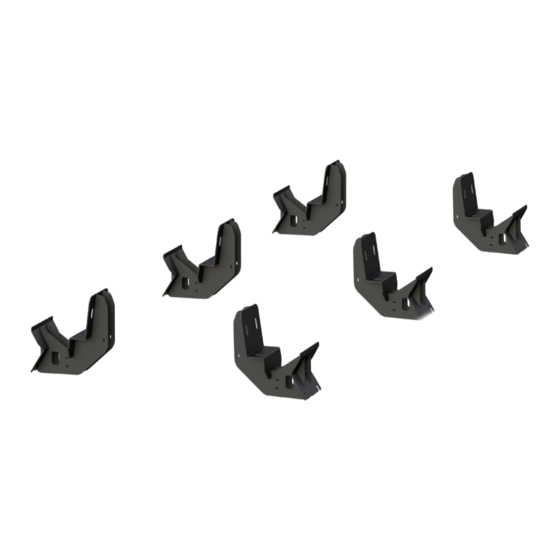
6
Mounting bracket, universal
6
T-rails
12
Clip nut, M8
12
Hex bolt, M8 x 25mm
24 Flat washer, M8
12
Lock washer, M8
12
Nylock nut, 5/16"
2
Rubber grommet
4
Door sensor
2
Door sensor extension
4
Magnet
2
Alcohol wipe
1
Power switch
1
Circuit board
1
Anti-seize
1
Wire loom
1
Wiring harness, two-piece
2
LED light
2
LED light bracket
4
Double-sided foam tape, 3/4" x 3/4"
8
Double-sided foam tape, 1/2" x 1/2"
* Running boards sold separately
Tools Required
Ratchet
Drill
Socket set
Drill bit set
Zip ties
Level
Torque Specifications
M6 bolt
3 ft-lbs.
M8 bolt
7 ft-lbs.
M10 bolt
16 ft-lbs.
1/4" bolt
3 ft-lbs.
5/16" bolt
7 ft-lbs.
3/8" bolt
16 ft-lbs.
7/16" bolt
20 ft-lbs.
1/2" bolt
28 ft-lbs.
Use above torque setting unless otherwise noted
NEED ASSISTANCE?
•
844.278.4357
WARNING
Improper electrical installation may result in personal injury. Unless
you are familiar with the installation and handling of electrical systems,
have this step performed by someone who has that familiarity.
Product Photo
Powered Running Boards (not included)
Part Numbers
3025104 (brackets)
3015104 (brackets)
Notes and Maintenance
Before you begin installation, read all instructions thoroughly.
Proper tools will improve the quality of installation and reduce the time required.
No maintenance required on waterproof harness or water-resistant motors.
If mud or dirt is built up on the steps, simply spray them off and let them air dry.
Mild automotive detergent may be used to clean the product. Do not use dish detergent, abrasive
cleaners, abrasive pads, wire brushes or other similar products that may damage the finish.
Periodic inspection of all wires and connections should be
performed to ensure there is no visible damage or loose connections.
Refer to the last page of this manual for troubleshooting,
warranty and product registration information.
Refer to the table to the left when securing hardware during the
installation process to help prevent damage to the product or vehicle.
•
RA
•
PAGE 1
Front
3025179 (boards)
3015179 (boards)
Rear
Middle
3047904 (brackets & boards)
3037904 (brackets & boards)
Advertisement

Related Manuals for Curt Manufacturing 3025104


Summary of Contents for Curt Manufacturing 3025104
- Page 1 Double-sided foam tape, 1/2" x 1/2" * Running boards sold separately Tools Required Ratchet Drill Part Numbers Socket set Drill bit set 3025104 (brackets) 3025179 (boards) 3047904 (brackets & boards) Zip ties Level 3015104 (brackets) 3015179 (boards) 3037904 (brackets & boards)
- Page 2 Step 1 Starting on the driver side, locate the three mounting locations underneath the vehicle. Step 2 Starting at the front driver-side mounting location, remove two hole plugs. Insert an M8 clip nut through the access hole and align it over the adjacent smaller hole.
- Page 3 Step 5 With help, carefully place the running board onto the mounting brackets. Align the T-rails with the mounting brackets on the vehicle. Slide the top mounting track on the board over the top flange on each bracket. Adjust the T-rails in the lower track of the board so the studs drop into the slots on the bottom of each mounting bracket.
- Page 4 Step 8 Remove the fuse from the wiring harness before installing. Once the fuse is removed, take that section of the wiring harness and attach it to the battery. Route the opposite end of the harness through the firewall into the cab of the vehicle. Zip-tie the wiring harness in place once it is in the desired location.
- Page 5 Step 10 Wiring Locations Once the trim panels are removed, take the Door sensor, rear Purple / Orange second section of wiring harness and route it Door sensor, front Yellow / Orange under the carpet, through the vehicle, from the passenger-side rear to the desired location.
- Page 6 Step 11 On the driver side, take the power wire and sensor wire (orange / yellow) and route it to the front of the vehicle underneath the carpet. If there is no plug in the floor behind the driver seat, skip to step 12. If there is a plug in the floor behind the driver seat continue this step.
- Page 7 Step 14 Plug the door sensor into the wiring harness and route it up the door frame, under the carpet. Note: Depending on the vehicle, you may need to use the supplied sensor harness extensions for the two front door sensors. Once the harness and sensor are routed to the desired location, wipe the sensor and door with the provided alcohol wipe.
- Page 8 Step 16 On the driver side, plug the rear actuator (red / black) into the running board and pull the extra wire back into the vehicle. Plug the LED light wire (brown / tan) into the LED light and secure it to the mounting bracket tab with the supplied jam nut.
- Page 9 Step 18 Once all wiring is installed, plug in the circuit board and place it underneath the carpet under the rear passenger seat. Attach the two wiring harnesses and re-install the fuse removed in step 8. Step 19 Congratulations on the installation of your new powered running boards.
-
Page 10: Product Registration
TROUBLESHOOTING & REGISTRATION Troubleshooting I just installed my steps and they are Double check the connections. Check the fuse to make sure it is plugged in. Is the on / off not coming down when I open the door. switch getting power? Is the circuit board plugged in? Are the door sensors plugged in? My switch is getting power, but The light is only supposed to be on when the system is turned on.
Need help?
Do you have a question about the 3025104 and is the answer not in the manual?
Questions and answers