Table of Contents
Advertisement
Quick Links
Atmel AVR10004: RCB256RFR2 – Hardware User Manual
Features
•
Stand-alone operable radio controller board (RCB)
•
Design based on the single-chip Atmel
®
®
IEEE
802.15.4, ZigBee
applications
•
FCC-ID: VW4A091786
•
SMA RF connector
•
Simple user interface with button and LEDs
•
Board information EEPROM containing
•
MAC address
•
Board identification, features, and serial number
•
Crystal calibration values
•
2 × AAA batteries for stand-alone operation
•
60-pin extension connector to interface with application-specific hardware
Introduction
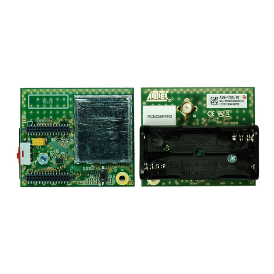
The RCB256RFR2 user manual describes the usage, design, and layout of the Atmel
ATmega256RFR2 radio controller board.
Figure 1.
RCB256RFR2 PCBA photo.
APPLICATION NOTE
8-bit Atmel Microcontrollers
®
ATmega256RFR2 to support
, 6LoWPAN, RF4CE, SP100, WirelessHART
®
, and ISM
42081A−AVR−03/2013
Advertisement
Table of Contents

Related Manuals for Atmel RCB256RFR2


Summary of Contents for Atmel RCB256RFR2
- Page 1 2 × AAA batteries for stand-alone operation • 60-pin extension connector to interface with application-specific hardware Introduction The RCB256RFR2 user manual describes the usage, design, and layout of the Atmel ATmega256RFR2 radio controller board. Figure 1. RCB256RFR2 PCBA photo. 42081A−AVR−03/2013...
-
Page 2: Table Of Contents
Radio certification ............29 United States (FCC) ..................29 Europe (ETSI) ....................30 Approved antenna ................... 30 Appendix C. References ..............31 Appendix D. EVALUATION BOARD/KIT IMPORTANT NOTICE ..32 Atmel AVR10004: RCB256RFR2 – Hardware User Manual [APPLICATION NOTE] 42081A−AVR−03/2013... - Page 3 Appendix E. Revision History RCB256RFR2 PCBA ......33 Appendix F. Revision History ............34 Atmel AVR10004: RCB256RFR2 – Hardware User Manual [APPLICATION NOTE] 42081A−AVR−03/2013...
-
Page 4: Disclaimer
Any information about third-party materials or parts was included in this document for convenience. The vendor may have changed the information that has been published. Check the individual vendor information for the latest changes. Overview The RCB256RFR2 is designed to provide a reference design for the Atmel ATmega256RFR2 single-chip ®... -
Page 5: Mechanical Description
(ETX0/1), separated by 22mm from each other, to interface to various port extension boards (base boards). The RCB256RFR2 has no on-board antenna, and so it is not required to separate the board into an electronics section and an antenna section. When used with a quarter-wave antenna mounted at the SMA connector, the board will act as a ground plane for the antenna. -
Page 6: Interface Connector Specification
The L2 in the part number indicates the low insertion force (LIF) variant to allow easy mounting. The drawing shown in Figure 3-2 is from a SAMTEC datasheet. Check the latest datasheet for possible updates and changes. Atmel AVR10004: RCB256RFR2 – Hardware User Manual [APPLICATION NOTE] 42081A−AVR−03/2013... -
Page 7: Application (Base) Board Connectors
Alternatively, a Tyco part can be used: Tyco 5-104655-4. Note: The Tyco part requires a different footprint design! The drawing shown in Figure 3-3 is from a SAMTEC datasheet. Check the latest datasheet for possible updates and changes. Atmel AVR10004: RCB256RFR2 – Hardware User Manual [APPLICATION NOTE] 42081A−AVR−03/2013... -
Page 8: Functional Description
Functional Description Figure 4-1 illustrates the RCB setup in general. It mainly consists of an Atmel ATmega256RFR2 and some peripheral circuitry. An ID EEPROM stores MAC address and additional board information. This information is stored in a separate EEPROM to avoid accidental data erasure during microcontroller firmware development. -
Page 9: Microcontroller
ISM applications, too. All spare I/O pins are accessible via the expansion connectors for external use. The Atmel ATmega256RFR2 is designed to operate at full 16MHz speed over the complete supply voltage range from 1.8V to 3.6V. -
Page 10: On-Board Peripherals
When mounted on a base board, I/O ports PE4 and PE5 are used to emulate #WR and #RD lines handling a memory interface. Therefore, the pushbutton and LED D4 are not functional. On RCB256RFR2, the port G I/O lines cannot be used because they are shared with dedicated radio transceiver functionality. - Page 11 Calibration values are used to optimize radio transceiver performance. Final products do not require this external ID EEPROM functionality. All data can be stored directly in the Atmel Atmega256RFR2 internal EEPROM. The ID EEPROM is there for convenience to simplify microcontroller firmware development.
-
Page 12: External Peripherals
PWM. Make sure that any RCB base board that is used together with the RCB256RFR2 will not drive the TST signal (EXT1, pin5) high during operation. The only occasion to drive the TST signal high is during parallel programming. Refer to for detailed information. - Page 13 AREF PF4 (TCK) PF5 (TMS) PF6 (TDO) PF7 (TDI) V_RCB V_RCB The connector pin-out mapping enables operation with almost all peripheral elements on existing base boards, except external SRAM support. Atmel AVR10004: RCB256RFR2 – Hardware User Manual [APPLICATION NOTE] 42081A−AVR−03/2013...
-
Page 14: Pcb Layout Description
Reduce any kind of spurious emissions well below the limits set by the individual regulatory organizations Layout details 1 to 9, as shown in Figure 4-4 Figure 4-5, are described in the following sub-sections. Atmel AVR10004: RCB256RFR2 – Hardware User Manual [APPLICATION NOTE] 42081A−AVR−03/2013... - Page 15 Figure 4-4. RCB256RFR2 top layer design details. Atmel AVR10004: RCB256RFR2 – Hardware User Manual [APPLICATION NOTE] 42081A−AVR−03/2013...
-
Page 16: Pcb Detail 1 - Balanced Rf Fan Out
Figure 4-5. RCB256RFR2 bottom layer design details. The RCB256RFR2 demonstrates a low-cost two-layer PCB design with a total thickness of 1.6mm. The chosen PCB material is FR4 (ISOLA IS400). The top and bottom layer each with 35µm copper are used as ground planes. -
Page 17: Pcb Detail 2 - Balun Ground Connection
It is recommended to design the ground trace as wide as possible to avoid parasitic inductances. Atmel Atmega256RFR2 analog ground pins are to be routed to the paddle underneath the IC. The GND trace width is recommended to be similar to the pad width. -
Page 18: Pcb Detail 6 - Ground Plane
PCB detail 8 – RF section shielding A shield covering the Atmel Atmega256RFR2 and related parts is used to protect the IC from external noise and strong interferers. The shield is not required to suppress any radiation generated by the IC. -
Page 19: Programming
All programming interfaces are available through two 50mil connectors (EXT0/1). Using an appropriate base board, the interfaces are available as 100mil connectors to directly connect programming tools such as JTAGICE mkII. The Atmel Atmega256RFR2 has the serial programming function mapped to port B. Refer to the Atmega256RFR2 datasheet for detailed pin descriptions. -
Page 20: Electrical Characteristics
Note: General RF specifications For general RF specifications, refer to the Atmel Atmega256RFR2 datasheet [1]. The RCB schematic follows the application circuit. The filter-balun and SMA connector result in a typical loss of 1dB in TX output power and sensitivity compared to the values as shown in the radio transceiver section. -
Page 21: Current Consumption Specifications
Current consumption specifications Power consumption figures of the individual Atmel Atmega256RFR2 building blocks and operation conditions are listed in the datasheet [1]. To determine the RCB current consumption, the following values are to be taken into account: (1) (2) Test conditions (unless otherwise stated) = 3.0V, T... -
Page 22: Abbreviations
Printed circuit board PCBA Printed circuit board assembled Radio controller board Radio frequency Receive Subminiature version A System on chip Two-wire serial interface Transmit USART Universal synchronous/asynchronous receiver/transmitter XTAL (Reference) crystal Atmel AVR10004: RCB256RFR2 – Hardware User Manual [APPLICATION NOTE] 42081A−AVR−03/2013... -
Page 23: Appendix A. Pcb Design Data
PCB design data Appendix A. Schematic Figure A-1. RCB256RFR2 – RF section. Atmel AVR10004: RCB256RFR2 – Hardware User Manual [APPLICATION NOTE] 42081A−AVR−03/2013... - Page 24 Figure A-2. RCB256RFR2 – SOC section 1. Be aware of the TST and CLKI signal routing on RCB256RFR2. The connector mapping is visible in Figure A-4, as well Note: as pull-down resistors (R8, R9) for both signals. For normal operation, the TST signal must be pulled to ground all the time.
- Page 25 Figure A-3. RCB256RFR2 – SOC section 2. Atmel AVR10004: RCB256RFR2 – Hardware User Manual [APPLICATION NOTE] 42081A−AVR−03/2013...
- Page 26 Figure A-4. RCB256RFR2 –I/O, ID EEPROM and power. Atmel AVR10004: RCB256RFR2 – Hardware User Manual [APPLICATION NOTE] 42081A−AVR−03/2013...
-
Page 27: Assembly Drawing
Assembly drawing Figure A-5. RCB256RFR2 – assembly drawing. Atmel AVR10004: RCB256RFR2 – Hardware User Manual [APPLICATION NOTE] 42081A−AVR−03/2013... -
Page 28: Bill Of Materials
LairdTech LT08AD4303 SPDT Eao09.10201.02 09.10201.02 Button SPST ITT KSR211GLFS KSR211GLFS EEPROM AT25010A ATMEL AT25010A AVR and transceiver ATMEGA256RFR2-ZU ATMEL ATMEGA256RFR2-ZU RF conn. SMA Vertical Multicomp. 19-46-1-TGG PSTG0-2400HS Antenna Mobile Mark Atmel AVR10004: RCB256RFR2 – Hardware User Manual [APPLICATION NOTE] 42081A−AVR−03/2013... -
Page 29: Appendix B. Radio Certification
Radio certification Appendix B. The RCB256RFR2 has received regulatory approvals for modular devices in the United States and European countries. United States (FCC) Compliance Statement (Part 15.19) The device complies with Part 15 of the FCC rules. To fulfill FCC Certification requirements, an original equipment manufacturer (OEM) must comply with the following regulations: •... -
Page 30: Europe (Etsi)
SMA connection. Table B-1. Approved antenna. Manufacturer Description Model Frequency Connector Mobile Mark ¼-wave stub antenna PSTG0-2400HS 2400 - 2490MHz Male SMA Atmel AVR10004: RCB256RFR2 – Hardware User Manual [APPLICATION NOTE] 42081A−AVR−03/2013... -
Page 31: Appendix C. References
[6] 2.45 GHz Harmonic Filter-Balun; Datasheet 2450FB15L0001; Johanson Technology, Inc. [7] AT25010A; SPI Serial EEPROM; Datasheet; Rev. 3348J-SEEPR-8/06; Atmel Corporation. [8] AVR2063; Sensor Terminal Board – Hardware User’s Manual; Application Note; Rev. 8359B-AVR-01/12; Atmel Corporation. Atmel AVR10004: RCB256RFR2 – Hardware User Manual [APPLICATION NOTE] 42081A−AVR−03/2013... -
Page 32: Appendix D. Evaluation Board/Kit Important Notice
The user assumes all responsibility and liability for proper and safe handling of the goods. Further, the user indemnifies Atmel from all claims arising from the handling or use of the goods. Due to the open construction of the product, it is the user’s responsibility to take any and all appropriate precautions with regard to electrostatic discharge and any other... - Page 33 Revision History RCB256RFR2 PCBA Appendix E. Version Description A09- 1786/01 Initial revision Atmel AVR10004: RCB256RFR2 – Hardware User Manual [APPLICATION NOTE] 42081A−AVR−03/2013...
- Page 34 Revision History Appendix F. Doc. Rev. Date Comments 42081A 03/2013 Initial document release Atmel AVR10004: RCB256RFR2 – Hardware User Manual [APPLICATION NOTE] 42081A−AVR−03/2013...
- Page 35 Other terms and product names may be trademarks of others. Disclaimer: The information in this document is provided in connection with Atmel products. No license, express or implied, by estoppel or otherwise, to any intellectual property right is granted by this document or in connection with the sale of Atmel products.
Need help?
Do you have a question about the RCB256RFR2 and is the answer not in the manual?
Questions and answers