Edwards nXDS6i Instruction Manual
Dry vacuum pump
Hide thumbs
Also See for nXDS6i:
- Instruction manual (24 pages) ,
- Replacement (17 pages) ,
- Instruction manual (52 pages)
Table of Contents
Advertisement
Quick Links
Dry Vacuum Pump
nXDS Scroll Pump
INSTRUCTION MANUAL
DESCRIPTION
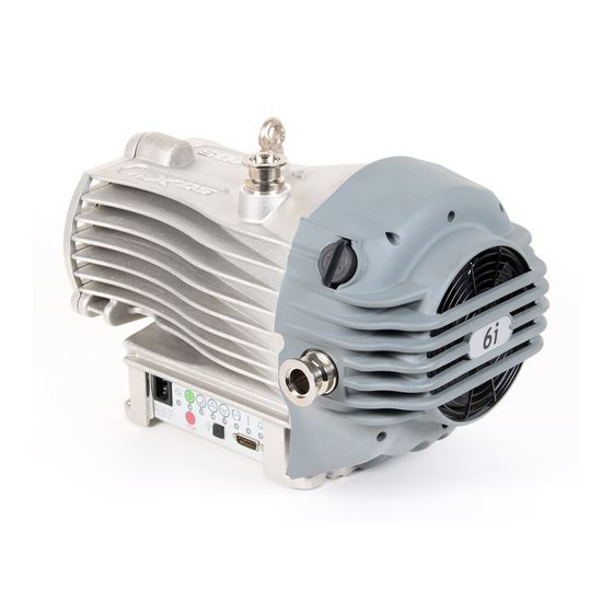
nXDS6i
nXDS10i
nXDS15i
nXDS20i
nXDS6iC
nXDS10iC
A73501880_G
ITEM NUMBER
DESCRIPTION
A73501983
nXDS15iC
A73601983
nXDS20iC
A73701983
nXDS6iR
A73801983
nXDS10iR
A73502983
nXDS15iR
A73602983
nXDS20iR
edwardsvacuum.com
ITEM NUMBER
A73702983
A73802983
A73503983
A73603983
A73703983
A73803983
Original instructions
Advertisement
Table of Contents

Related Manuals for Edwards nXDS6i


Summary of Contents for Edwards nXDS6i
- Page 1 Dry Vacuum Pump nXDS Scroll Pump INSTRUCTION MANUAL edwardsvacuum.com DESCRIPTION ITEM NUMBER DESCRIPTION ITEM NUMBER nXDS6i A73501983 nXDS15iC A73702983 nXDS10i A73601983 nXDS20iC A73802983 nXDS15i A73701983 nXDS6iR A73503983 nXDS20i A73801983 nXDS10iR A73603983 nXDS6iC A73502983 nXDS15iR A73703983 nXDS10iC A73602983 nXDS20iR A73803983 A73501880_G...
- Page 2 Serial Comms Interface Instruction Manual A73501860 Trademark credit Edwards and the Edwards logo are trademarks of Edwards Limited, Innovation Drive, Burgess Hill, West Sussex RH15 9TW. Disclaimer The content of this manual may change from time to time without notice. We accept no liability for any errors that may appear in this manual nor do we make any expressed or implied warranties regarding the content.
- Page 3 CE Declaration of Conformity Edwards Ltd Innovation Drive Burgess Hill West Sussex RH15 9TW The following product nXDS6i scroll pump 100-127/200-240V, 50/60Hz A735-01-983 nXDS10i scroll pump 100-127/200-240V, 50/60Hz A736-01-983 nXDS15i scroll pump 100-127/200-240V, 50/60Hz A737-01-983 nXDS20i scroll pump 100-127/200-240V, 50/60Hz...
- Page 4 Additional Legislation and Compliance Information EU EMC Directive: Class A/B Industrial equipment Caution: This equipment is not intended for use in residential environments and may not provide adequate protection to radio reception in such environments. EU RoHS Directive: Material Exemption Information This product is compliant with the following Annex III Exemptions 6(b) Lead as an alloying element in aluminium containing up to 0.4% by weight •...
-
Page 5: Table Of Contents
Contents 1. Safety and compliance........7 1.1 Definition of Warnings and Cautions. - Page 6 5.1 Operational modes..........31 5.2 Manual operation.
- Page 7 9.2.2 Gas ballast adaptor........50 9.2.3 Gas ballast adaptor blank.
- Page 8 Figure 3: nXDS6i Performance characteristics........
-
Page 9: Safety And Compliance
A73501880_G - Safety and compliance 1. Safety and compliance 1.1 Definition of Warnings and Cautions NOTICE: This manual meets our obligation to provide you with information. For safe operation from the start, read these instructions carefully before you install or commission the equipment. - Page 10 A73501880_G - Safety and compliance Warning/Caution A safety instruction which must be followed. Warning - Heavy object Identifies a possible hazard from a heavy object. Warning - Dangerous voltage Identifies possible hazards from dangerous voltages. Warning - Hot surfaces Identifies a potential hazard from a hot surface. Warning - Risk of explosion An indication that there is a risk of explosion when you do the task.
-
Page 11: Introduction
A73501880_G - Introduction 2. Introduction 2.1 Scope of this manual This manual provides installation, operation and maintenance instructions for the nXDS series of scroll pump. The pump must be used as specified in this manual or the protection provided by the equipment may be impaired. Read this manual before installing and operating the pump. -
Page 12: Description
A73501880_G - Introduction When planning to pump hazardous substances with this pump, read the related chapters in the Safety Booklet and in these Operating Instructions first. Further details can be obtained by contacting us. 2.3 Description The nXDS pump is shown in Figure: nXDS scroll pump on page The nXDS pump is a dry vacuum pump as all the bearings, with their hydrocarbon lubricant, are isolated from the vacuum space. -
Page 13: Logic Interface
A73501880_G - Introduction Figure 1 nXDS scroll pump 1. Lifting eye 1. Lifting eye 2. NW25 inlet port 2. NW25 inlet port 3. Gas ballast control 3. Gas ballast control 4. Cooling fan 4. Cooling fan 5. NW25 exhaust port 5. -
Page 14: Figure 2 Quick Start Guide (Manual Control Mode)
A73501880_G - Introduction supplied through a suitable external valve and by using the appropriate adaptor, available as an accessory. Refer to Spares and accessories on page Figure 2 Quick start guide (manual control mode) OPERATION SELECT STATUS SECTION The pump will remain off (factory Electrical supply MAINS default). - Page 15 A73501880_G - Introduction OPERATION SELECT STATUS SECTION The pump speed will increase. STANDBY The INCREASE STANDBY INDICATOR SPEED Standby on page will remain illuminated when the INCREASE Increase or pump reaches a maximum of 100% of BUTTON decrease the full speed. pump speed The pump speed will decrease.
- Page 16 A73501880_G - Introduction Manual/ Configuration Control mode Section Analogue speed control on page 33 Parallel control via Figure: Logic Digital I/O and interface Analogue speed connections - control source analogue speed control on page 34 Serial control via Manual RS232 or RS485 A73501860 Comms Interface Note:...
-
Page 17: Technical Data
* The product can be used up to an altitude of 3000 m. However, the product is only ETL certified for use up to 2000 m. 3.2 Performance Table 4 General characteristics Description nXDS6i nXDS10i nXDS15i nXDS20i 11.4 15.1 22.0... -
Page 18: Pumping Media
A73501880_G - Technical data Description nXDS6i nXDS10i nXDS15i nXDS20i Leak tightness (mbar l s 1 x 10 1 x 10 1 x 10 1 x 10 * These pumps are designed to pump down from atmospheric pressure, but prolonged operation at inlet pressures higher than specified may reduce bearing life. -
Page 19: Figure 3 Nxds6I Performance Characteristics
7 x 10 7 x 10 3 x 10 Pump ultimate(mbar) Gas ballast position 5 x 10 4 x 10 4 x 10 6 x 10 Gas ballast flow Gas ballast position (l min Figure 3 nXDS6i Performance characteristics Page 17... -
Page 20: Figure 4 Nxds10I Performance Characteristics
A73501880_G - Technical data Figure 4 nXDS10i Performance characteristics Figure 5 nXDS15i Performance characteristics Page 18... -
Page 21: Mechanical Data
A73501880_G - Technical data Figure 6 nXDS20i Performance characteristics 3.3 Mechanical data Table 6 General mechanical data Parameter nXDS Overall dimensions (L x W x H) 432 x 282 x 302 mm Maximum tilt angle 10 degrees Nominal rotational speed 1800 rpm (30 Hz) 6i ‑... -
Page 22: Construction
A73501880_G - Technical data Parameter nXDS Vibration: measured at the inlet port (ISO Class 1C...< 4.5 mm s (rms radial) 3744) 3.3.2 Construction All surfaces of the pump which are exposed to the pumped gases are free from copper, zinc and cadmium. Exposed components include: anodised aluminium scrolls, aluminium housing, nickel‑plated inlet and exhaust ports, PTFE composite tip‑seals, various stainless steel parts and fluorocarbon elastomer seals. -
Page 23: Logic Interface Data
A73501880_G - Technical data Description Rating Coupler type Item number Plug Type = European Schuko VDE approved, 16 A 250 V rated with dual earthing contact Appliance Coupler = IEC60320 style C14 Cord set Cable style = SJT, 3 x 18 AWG, 300 V, assembly, 70 °C, VW‑1 maximum length of Straight entry... - Page 24 A73501880_G - Technical data Logic interface description Type Open collector transistor plus pull up resistor. < Normal speed (default 80%) OFF (4.7 k pull up + diode to 12 V d.c.) ³ Normal speed ON (< 0.8 V d.c. sinking 10 mA) Maximum current rating 10 mA Maximum voltage rating...
-
Page 25: Led Indicators
A73501880_G - Technical data Signal Polarity Use Number Analogue Speed ‑ 0‑10 V analogue Input: 0 V = 0% Speed; Control Input + 10 V = 100% speed Chassis/Screen Screen + 10 V Analogue Positive + 10 V analogue voltage reference Reference ‑... - Page 26 A73501880_G - Technical data Description Details Standby speed decrease The indicator will blink with every short push of the indicator Standby speed decrease button. The indicator will remain ON when minimum standby speed has been reached. Refer to Standby on page Auto‑run indicator Indicates that the Auto‑run mode has been selected.
-
Page 27: Installation
A73501880_G - Installation 4. Installation 4.1 Safety WARNING: Obey the safety instructions in this section and take note of appropriate precautions. If not, injury to people and damage to equipment can result. Prevent any part of the human body coming into contact with the vacuum. The nXDS pump is not intended for pumping explosive gases continuously (refer to ATEX directive implication on page Ensure that the pump is suitable for the application. -
Page 28: Figure 8 Installation Drawing
A73501880_G - Installation Figure 8 Installation drawing Note: All dimensions in mm. External dimensions are the same for all variants. Page 26... -
Page 29: Unpack And Inspect
A73501880_G - Installation 4.3 Unpack and inspect WARNING: Use suitable lifting equipment to move the nXDS pump. The maximum pump mass is 27 kg. Mechanical lifting equipment should be attached to the lifting eye; Loose slings should not be used. Take care when moving the pump into position. -
Page 30: Connect To The Vacuum System
A73501880_G - Installation 4.5 Connect to the vacuum system WARNING: If pumping dangerous gases or vapours, connect the exhaust to a suitable treatment plant to prevent the discharge of dangerous gases and vapours to the surrounding atmosphere. If the pump is operated with the exhaust line blocked, high pressure may be generated in the exhaust line pipework. -
Page 31: Electrical Installation
A73501880_G - Installation 4.6 Electrical installation 4.6.1 Fuses and circuit breakers WARNING: Ensure that the electrical installation of the pump conforms to local and national safety requirements. The pump must be connected to a suitably fused and protected electrical supply with a suitable earth point. For recommended fuse ratings and cord sets refer to Electrical data on page CAUTION:... - Page 32 A73501880_G - Installation To control the pump using the hardware parallel interface, refer to Parallel control and monitoring on page 33 for more information. To use the serial interface or to work with a mixture of parallel and serial control, refer to manual A73501860. Page 30...
-
Page 33: Operation
A73501880_G - Operation 5. Operation WARNING: Ensure that the system design does not allow the exhaust pipeline to become blocked. CAUTION: A fine dust may be emitted from the exhaust of the scroll pump during start up, particularly when the pump is new or if new tip seals are fitted. 5.1 Operational modes The nXDS pump implements three control modes: Manual Control Mode ‑... -
Page 34: Start And Stop
A73501880_G - Operation Figure 9 User interface panel 1. Mains power connector 1. Mains power connector 2. Power connected indicator 2. Power connected indicator 3. Start button with indicator 3. Start button with indicator 4. Standby button with indicator 4. Standby button with indicator 5. -
Page 35: Parallel Control And Monitoring
A73501880_G - Operation 5.3 Parallel control and monitoring Figure 10 Logic interface connections - parallel control 1. Start switch 1. Start switch 2. Standby switch (optional) 2. Standby switch (optional) 3. nXDS pump logic interface 3. nXDS pump logic interface CAUTION: If using the normal and fail lines to drive the coils of d.c. -
Page 36: Figure 11 Logic Interface Connections - Analogue Speed Control
A73501880_G - Operation Figure 11 Logic interface connections - analogue speed control 1. Start switch 1. Start switch 2. Analogue control switch 2. Analogue control switch 3. nXDS pump logic interface 3. nXDS pump logic interface Note: Note: º 1% of Default Run Speed. º... -
Page 37: Hardware Configuration
A73501880_G - Operation 5.4.1 Hardware configuration Using the 15‑way D‑type connector (Figure: nXDS scroll pump on page 11, item 7) apply the following signal configurations to enable the Analogue Speed Control source (refer Table: Logic interface connector pins on page 22): Connect the Analogue Speed Enable control input (pin 1) to the 0 V Control Reference (pin 2). -
Page 38: Start Up Procedure
A73501880_G - Operation Gas ballast OFF (position 0). Use this setting to: • achieve ultimate vacuum • pump dry gases. Gas ballast ON (position 1). Use this setting to: • pump low concentrations of condensable vapours • decontaminate the pump. 5.7 Start up procedure Use the procedure below to start up the pump: Ensure that any vacuum system isolation valve is closed (if fitted). - Page 39 A73501880_G - Operation Close any vacuum system isolation valves to prevent suck‑back into the vacuum system (where fitted). Stop the pump system using the appropriate control source, that is, using the Stop button in manual control mode (refer to Figure: User interface panel on page 32);...
-
Page 40: Maintenance
A73501880_G - Maintenance 6. Maintenance 6.1 Safety information WARNING: Obey the safety instructions in this section and take note of appropriate precautions. Failure to observe these instructions may result in injury to people and damage to equipment. WARNING: In order to maintain the ATEX certification, all maintenance work must be carried out in accordance with this nXDS instruction manual, the Replacement tip seal manual and the nXDS maintenance manual, only using our genuine spare parts. -
Page 41: Maintenance Plan
A73501880_G - Maintenance ▪ Ensure the maintenance is done by a suitably trained and supervised technician. Obey local and national safety requirements. ▪ Ensure the maintenance technician is familiar with the safety procedures which relate to the products processed by the pumping system. ▪... -
Page 42: Check The Pump Performance (Service Indicator)
A73501880_G - Maintenance Switch off the pump and disconnect it from the electrical supply. Use a dry cloth and a soft brush to remove dirt and deposits from the fan cover. 6.5 Check the pump performance (service indicator) The service indicator, (flashing ON 1s / OFF 1s) is triggered as a reminder to check the performance of the pump. -
Page 43: Replace The Pump Controller (Service Indicator)
A73501880_G - Maintenance It is possible for an experienced technician, who is suitably trained, to perform maintenance and repair on nXDS pumps up to and including bearing replacement. We have developed a detailed maintenance manual and instructional video (part number A73501713) that will enable an experienced technician to undertake this work. - Page 44 A73501880_G - Maintenance Note: Resetting the pump bearing service indicator will also reset the performance check timer, that is, both counters will be set to zero. Resetting the service indicator will reset the service timer back to zero (refer to Table: Maintenance plan on page 39).
-
Page 45: Fault Finding
A73501880_G - Fault finding 7. Fault finding 7.1 The pump has failed to start or has stopped ▪ The electrical supply fuse has blown. ▪ The ambient temperature is too high. ▪ The cooling air supply is insufficient or is too hot. ▪... -
Page 46: The Pump Is Noisy
A73501880_G - Fault finding Figure 13 Poor ultimate vacuum flow chart 7.4 The pump is noisy If the pump is noisy, refer to Figure: Noisy pump flow chart on page Page 44... -
Page 47: The Pump Surface Temperature Is High
A73501880_G - Fault finding Figure 14 Noisy pump flow chart 7.5 The pump surface temperature is high ▪ The ambient temperature is too high. ▪ The cooling fan is not running. ▪ The process gas is too hot or the maximum continuous operating pressure has been exceeded. - Page 48 A73501880_G - Fault finding Table 16 Flashing error codes Error flash Error flash Comment Actions position sequence Check whether the pump is not running under constant high ssssss Overload timeout. pressure or the inlet or outlet is not blocked. Cycle the power to the pump and Controller software see whether the error code appears Lsssss...
-
Page 49: Storage And Disposal
A73501880_G - Storage and disposal 8. Storage and disposal 8.1 Storage Use the following procedure to store the pump: Shut down the pump as described in Shut down on page Disconnect the pump from the electrical supply. Place and secure protective covers over the inlet and outlet ports. Store the pump in cool, dry conditions until required for use. -
Page 50: Spares And Accessories
A73501880_G - Spares and accessories 9. Spares and accessories 9.1 Introduction Our products, spares and accessories are available from our companies in Belgium, Brazil, China, France, Germany, Israel, Italy, Japan, Korea, Singapore, United Kingdom, U.S.A and a world-wide network of distributors. The majority of these centres employ Service Engineers who have undergone our comprehensive training courses. -
Page 51: Accessories
A73501880_G - Spares and accessories 9.2 Accessories Figure 15 nXDS accessories 1. Gas ballast adaptor blank 1. Gas ballast adaptor blank 2. Gas ballast adaptor 2. Gas ballast adaptor 3. 3a+3b Inlet/exhaust filter 3. 3a+3b Inlet/exhaust filter 4. Silencer 4. Silencer 5. -
Page 52: Silencer
A73501880_G - Spares and accessories 9.2.1 Silencer A silencer is available for the nXDS pump. Refer to Connect to the vacuum system on page 28 for guidance on its use. Table 17 Silencer Product description Ordering information Silencer NW25 A50597000 9.2.2 Gas ballast adaptor A gas ballast adaptor may be fitted in place of the gas ballast control on the pump. -
Page 53: Exhaust Nozzle
A73501880_G - Spares and accessories Note: If connecting the exhaust filter onto the pump outlet, an NW25 / hose nozzle, C10514328 is available to connect onto the outlet of the dust filter. Table 20 Inlet/exhaust filter Product description Ordering information Inlet/exhaust filter NW25/NW25 A50597805 9.2.6 Exhaust nozzle... -
Page 54: Pump-To-Controller Cable
A73501880_G - Spares and accessories 9.2.9 Pump-to-controller cable Use the control cable to control the nXDS pump using Turbo Instrument Controller (TIC) or TIC Turbo Controller, or a (TAG) Turbo and Active Gauge controller. Table 24 Pump-to-controller cables Product description Ordering information 1 m cable D39700835... -
Page 55: Inlet/Exhaust Filter Spares
A73501880_G - Spares and accessories 9.3.5 Inlet/exhaust filter spares Replacement elements for the inlet/exhaust filter A50597805. Table 29 Inlet/exhaust filter spares Product description Ordering information 5 micron element A50597802 1 micron element A50597803 9.3.6 Bearing replacement kit (not field serviceable) Used when the pump has reached a long run service interval. -
Page 56: Service
A73501880_G - Service 10. Service 10.1 Return the equipment or components for service Before you send your equipment to us for service or for any other reason, you must send us a completed Declaration of Contamination of Vacuum Equipment and Components – Form HS2. - Page 57 A73501880_G - Service Page 55...
- Page 58 edwardsvacuum.com...
Need help?
Do you have a question about the nXDS6i and is the answer not in the manual?
Questions and answers