
Related Manuals for CLEAN ROOM DEVICES CRD216SS


Summary of Contents for CLEAN ROOM DEVICES CRD216SS
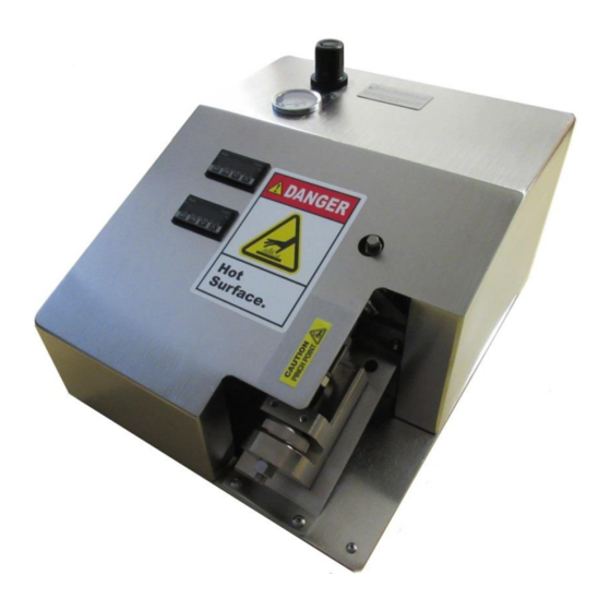
- Page 1 CRD216SS TIME DELAY HEATED TUBING EXPANDER OPERATIONS MANUAL VERSION 2.7 LAST EDITED 01.07.2021 cleanroomdevices.com...
-
Page 2: Table Of Contents
Table of Contents Table of Contents…………………….…………………………………………………………...2 General Product & Safety Information…………………………………………….…..…3 Product Information Safety Information Installation………………………………………………….………………..….………..4 Air Supply A/C Power Connection Setup Operation…………………………………………………………………..……...…..….5 Tube Expanding Jaw Installation and Removal Setting the Time Delays Maintenance…………………………………………………………………….…….…14 Verifying temperature Periodic Cleaning (annually) Heater Calibration (Delta Controls) Troubleshooting………………………………………………………………………..18 Product Specifications………………………………………………………………..…19 Durometer Scale………………………………………………………………………...19... -
Page 3: General Product & Safety Information
1.0 General Product & Safety Information Product Information The CRD216SS is designed to expand stiffer tubing such as nylon, polyethylene, polypropylene and Teflon tubing. With the heater off, the unit can also expand flexible tubing up to a durometer of Shore A 85 (Shore D 35), including any non-metallic braided materials ... -
Page 4: Installation
24VDC power source. Both must be present to operate. Connection Setup Connections on the CRD216SS are simple. Refer to Figure 2.3.1 below when making all connections to the back panel. Jaw Hold-Open... -
Page 5: Operation
Figure 2.3.1 3.0 Operation Tube Expanding Jaw Set Thumb Wheel Locking Hex Nut CAUTION: THE UNIT CAN BECOME EXTREMELY HOT. CARE MUST BE USED AT ALL TIMES WHEN EXPENDING AND DURING JAW INSTALLATION AND REMOVAL. To adjust the jaws for the size tubing to be expanded you need to first loosen the Locking Hex Nut. - Page 6 Once the tube is expanded, release the foot pedal, rotate the tubing 90 degrees on the jaws and actuate the Tube Expander by pressing the foot pedal again. Note: Several expanding actions may be necessary to effectively expand the end of the tube for the fitting/connector to slide in.
-
Page 7: Jaw Installation And Removal
Jaw Installation and Removal CAUTION: THE UNIT CAN BECOME EXTREMELY HOT. CARE MUST BE USED AT ALL TIMES WHEN EXPENDING AND DURING JAW INSTALLATION AND REMOVAL. Tools required are 3/8”, 9/16” and 11/16” open ended wrenches, 2mm, 2.5mm, 3mm, 4mm and 3/32nds hex wrenches. - Page 8 Figure 3.2.3 Using a 3/8” open end wrench to hold the flats on the cylinder shaft and an 11/16” open end wrench on the hex nut, break the upper jaw nut loose by turning it counter clockwise. Figure 3.2.4 ...
- Page 9 Remove two 5x20mm screws Figure 3.2.6 Place two fingers under the cylinder shaft and lift until the upper jaw clears the lower jaw. Figure 3.2.7 and 3.2.8 Figure 3.2.7 Figure 3.2.8 Use a 2mm hex wrench to loosen the set screws in each jaw and then remove the heating element probes.
- Page 10 Figure 3.2.9 Figure 3.2.10 Flip the cylinder backwards until it stops. Figure 3.2.11 Figure 3.2.11 Rotate the upper jaw by hand turning it counter clockwise until the jaw can be removed. Important note: when screwing upper jaw onto cylinder shaft it is important to only screw the jaw 1/2 to 2/3 of the way on.
-
Page 11: Setting The Time Delays
Figure 3.2.12 Select replacement jaw set and assemble them in the reverse order of previous operations. Be sure to replace the thermocouples and heater cartridges in the correct positions. The unit will not operate correctly otherwise. Note: If the UP/DOWN alignment of the jaws are incorrect the cylinder shaft won’t retract when trying to be cycled. - Page 12 The CRD216SS expansion operation is designed to let the operator expand each piece of tubing twice. After the first expansion, the jaws will close and the operator rotates the tube 90 degrees and the jaws will automatically expand again using the sensor. This ensures that the tubing is expanded in a uniform fashion, and not deformed in only one direction.
- Page 13 Figure 3.3.2 Figure 3.3.3 below shows the CRD216SS with the rear cover removed, as well as the location of both time delay adjustments on the time delay relay: Interval Time Expansion Time Adjustment Adjustment Figure 3.3.3...
-
Page 14: Maintenance
4.0 Maintenance Verifying Temperature To verify the operational temperature, place a ring terminal measuring probe between the thermocouple and the upper jaw, as shown below: Spade-head probe and connector Probe placed between thermocouple & jaw Periodic Cleaning (annually) Wipe down outer surfaces with alcohol, septihol or mild detergents as required. ... - Page 15 Press to store desired temperature Lower Temperature Raise Temperature Figure 4.3.1...
- Page 16 4.4 Delta DTB Controller User Guide At power-up Temperature Controller displays "no Cont" * No thermocouple connected to controller * ** Thermocouple is polarity sensitive ** Press "Set" key for more than 3 seconds to enter Initial Setting Mode “up” & “down” Press key to change inPt to the thermocouple type connected to Temperature Controller Press "Set"...
- Page 17 temperature goes high for two minutes CoSH Communication Write Function C-SL Communication Format ASCII C-no Communication Address Communication Baud Rate 38y4 Data Length Prty Parity None Stop Stop Bit Press "SET" key for less than 3 seconds to enter Regulation Mode Regulation Mode Parameter Explanation...
-
Page 18: Troubleshooting
Notes: 1 - To reset controller to factory default settings: Place controller into !':I keys simultaneously for more then LoC 1 mode, press the seconds, press the key to display PASS, change number 1357, press SET, cycle power to the controller 2 - To release lock, press SET and ~keys Simultaneously... -
Page 19: Product Specifications
Product Specifications Unit Weight 21 LBS / 9.5 KG Overall Dimensions 14.5 in. lg. x 12 in. w. x 9 in. ht. Minimum Facility Air Supply 100 PSI Unit Air Regulator Setting 80-120 PSI 7.0 Durometer Scale Electrical Diagrams... -
Page 20: Parts List
Parts List Item No. Part No. Description 216-001 Base 216-004 Cover P00088 TEMPERATURE CONTROLLER P00490 FAN, COOLING, 3.15 SQ X 1.00 DP, MCM 1976K910 P00111 PRESSURE GAUGE, PANEL MOUNT, 0-160 PSI P00063 FITTING, AIR, 90 DEG. ELBOW, 1/4 TUBE, 1/8NPT P00066 REGULATOR, AIR, 1/8 NPT P00067... - Page 21 P00056 WASHER, .375, 300 SS CD002-137 KNOB, THUMB P00059 HEX NUT, .375-16, 18-8 SS CD002-138 BLOCK SUPPORT LONG P00058 HEX NUT, .438-20, 18-8 SS P00085 HEX NUT, 3/4-16, ZINC-PLATED STEEL P00141 FLOW VALVE, 1/8" NPT, 1/4" TUBE OD, METER IN P00620 AIR CYLINDER, 1.5 BORE X 1.0 STROKE P00022...
-
Page 22: Warranty
For additional information contact: www.cleanroomdevices.com Clean Room Devices, Inc. 10855 Dover Street, Suite 100 Westminster, CO 80021...
Need help?
Do you have a question about the CRD216SS and is the answer not in the manual?
Questions and answers