
Related Manuals for CLEAN ROOM DEVICES CRD216SS


Summary of Contents for CLEAN ROOM DEVICES CRD216SS
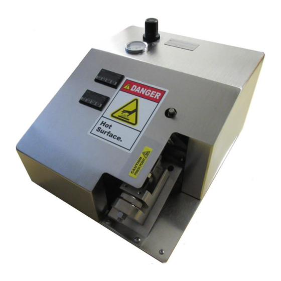
- Page 1 CRD216SS TIME DELAY HEATED TUBING EXPANDER OPERATIONS MANUAL VERSION 2.8 LAST EDITED 05.11.2022 cleanroomdevices.com...
-
Page 2: Table Of Contents
Table of Contents Table of Contents…………………….…………………………………………………………...2 General Product & Safety Information…………………………………………….…..…3 Product Information Safety Information Installation………………………………………………….………………..….…….…..5 Air Supply A/C Power Connection Setup Operation…………………………………………………………………..……...…...….5 Jaw Adjustment Setting Time Delays Expanding Operations Jaw Installation and Removal Maintenance…………………………………………………………………….…….…17 Verifying temperature Periodic Cleaning (annually) Heater Calibration (TEMPCO Controls) Troubleshooting………………………………………………………………….……..19 Product Specifications………………………………………………………..………..…19... -
Page 3: General Product & Safety Information
1.0 General Product & Safety Information Product Information • The CRD216SS is designed to expand stiffer tubing such as nylon, polyethylene, polypropylene and Teflon tubing. With the heater off, the unit can also expand flexible tubing up to a durometer of Shore A 85 (Shore D 35), including any non-metallic braided materials. - Page 4 WARNING Avoid placing your fingers between the upper jaw block and the air cylinder mounting bracket while operating unit, sufficient pressure exists to cause personal injury. Arrows indicate pinch points WARNING • During heating and once the unit reaches operating temperature, the jaws and metallic areas around the jaws will be extremely hot.
-
Page 5: Installation
24VDC power source. Both must be present to operate. Connection Setup • Connections on the CRD216SS are simple. Refer to Figure 2.3.1 below when making all connections to the back panel. -
Page 6: Jaw Adjustment
Toggle Switch Heater Controller Power Switch Jaw Hold-Open Toggle Switch Power Jack Foot Pedal Jack Air IN 120/240 VAC IN Figure 2.3.1 3.0 Operation Jaw Adjustment Jaw Set Thumb Wheel Lock Nut... - Page 7 Figure 3.1.1 Jaw Adjustment CAUTION: THE UNIT CAN BECOME EXTREMELY HOT. CARE MUST BE USED AT ALL TIMES WHEN EXPANDING AND DURING JAW INSTALLATION AND REMOVAL. • Start by using a 9/16” wrench to loosen the 3/8” hex nut at the bottom end of the lower jaw support block assembly to adjust the unit for the proper tubing size.
-
Page 8: Setting Time Delays
Figure3.1.A.5 Setting the Time Delays • The CRD216SS expansion operation is designed to let the operator expand each piece of tubing twice. After the first expansion, the jaws will close and the operator rotates the tube 90 degrees and the jaws will automatically expand again using the sensor. This ensures that the tubing is expanded in a uniform fashion, and not deformed in only one direction. - Page 9 • Using a small Phillips drive screwdriver adjust the Time Delay relays. Figure 3.2.2 Figure 3.2.2 Adjusting the Expansion Time Pot • Figure 3.2.3 below shows the CRD216SS with the electronics cover removed, as well as the location of both time delay adjustments on the time delay relay:...
-
Page 10: Expanding Operations
Interval Time Expansion Time Adjustment Adjustment Figure 3.2.3 Expanding Operation CAUTION: THE UNIT CAN BECOME EXTREMELY HOT. CARE MUST BE USED AT ALL TIMES WHEN EXPENDING AND DURING JAW INSTALLATION AND REMOVAL. • To adjust the jaws for the size tubing to be expanded you need to loosen the 3/8” hex nut (Lock Nut.) •... -
Page 11: Jaw Installation And Removal
Note: Several expanding actions may be necessary to effectively expand the end of the tube for the fitting/connector to slide in. Each time you expand the tubing remember to rotate the tubing 90 degrees on the jaws. Jaw Set Safety Guard Thumb Wheel Lock Nut Jaw Installation and Removal... - Page 12 • Remove the two 4x8mm screws attaching the Thermocouples to the upper and lower jaw using a 2.5mm hex wrench. Figure 3.4.1 and 3.4.2 Note: Be sure to label each thermocouple and/or heater cartridge as to its position, upper or lower, and be sure to replace them in the correct positions.
- Page 13 Figure 3.4.4 Figure 3.4.5 • Now remove the two 5x20mm screws holding the front cylinder mount bracket using a 4mm hex wrench. Figure 3.4.6. Remove two 5x20mm screws Figure 3.4.6 • Place two fingers under the cylinder shaft and lift until the upper jaw clears the lower jaw.
- Page 14 Figure 3.4.7 Figure 3.4.8 • Use a 2mm hex wrench to loosen the set screws in each jaw and then remove the heating element probes. Figure 3.4.9 and 3.4.10 Note: The set screws may be located on either the inner or outer faces of the jaws. Figure 3.4.9 Figure 3.4.10 •...
- Page 15 Figure 3.4.11 • Rotate the upper jaw by hand turning it counter clockwise until the jaw can be removed. • Important note: when screwing upper jaw onto cylinder shaft it is important to only screw the jaw 2/3 to 3/4 of the way on. Any farther and the jaw may slip off the jaw block when the cylinder is retracted.
- Page 16 Rotate rod while holding lower jaw Figure 3.4.14 • Select replacement jaw set and assemble them in the reverse order of previous operations. Be sure to replace the thermocouples and heater cartridges in the correct positions. The unit will not operate correctly otherwise. •...
-
Page 17: Maintenance
4.0 Maintenance Verifying Temperature • To verify the operational temperature, place a ring terminal measuring probe between the thermocouple and the upper jaw, as shown below: Spade-head probe and connector Probe placed between thermocouple & jaw Periodic Cleaning (annually) • Wipe down outer surfaces with alcohol, septihol or mild detergents as required. •... - Page 18 Function Key Raise Temperature Lower Temperature Figure 4.3.1 4.4 TEMPCO Temperature Controller • To set the controller to “Auto Tune” Mode: Press the “Function” key four times. The unit should display “A--t”. Press and hold the “Function” key until the display flashes. If the “Function”...
-
Page 19: Troubleshooting
5.0 Troubleshooting Operating Error Action 1. Check the facility air connection. Unit does not operate. 2. Check all air hose connections on the unit. 1. Ensure the tubing being expanded does not exceed the recommended durometer. 2. Ensure the lower jaw has been adjusted Flexible tubing is splitting/tearing. -
Page 20: Electrical Diagram
Electrical Diagrams Note: Schematic drawings are provided for troubleshooting only— not for modifying the machine in any way! -
Page 21: Parts List
Parts List Item No. Part No. Description 216-001 Base 216-004 Cover P00088 TEMPERATURE CONTROLLER P00490 FAN, COOLING, 3.15 SQ X 1.00 DP, MCM 1976K910 P00111 PRESSURE GAUGE, PANEL MOUNT, 0-160 PSI P00063 FITTING, AIR, 90 DEG. ELBOW, 1/4 TUBE, 1/8NPT P00066 REGULATOR, AIR, 1/8 NPT P00067... - Page 22 P00056 WASHER, .375, 300 SS CD002-137 KNOB, THUMB P00059 HEX NUT, .375-16, 18-8 SS CD002-138 BLOCK SUPPORT LONG P00058 HEX NUT, .438-20, 18-8 SS P00085 HEX NUT, 3/4-16, ZINC-PLATED STEEL P00141 FLOW VALVE, 1/8" NPT, 1/4" TUBE OD, METER IN P00620 AIR CYLINDER, 1.5 BORE X 1.0 STROKE P00022...
-
Page 23: Warranty
For additional information contact: www.cleanroomdevices.com Clean Room Devices, Inc. 10855 Dover Street, Suite 100 Westminster, CO 80021...
Need help?
Do you have a question about the CRD216SS and is the answer not in the manual?
Questions and answers