Table of Contents
Advertisement
Available languages
Available languages
Quick Links
Advertisement
Chapters
Table of Contents

Subscribe to Our Youtube Channel
Related Manuals for HAMPTON BAY Fulton 140201


Summary of Contents for HAMPTON BAY Fulton 140201
-
Page 2: Table Of Contents
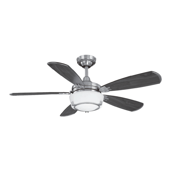
52” Fulton Thank you for purchasing this Hampton Bay ceiling fan. This product has been manufactured with the highest standards of safety and quality. The finish Ceiling Fan by Hampton Bay of this fan is weather resistant, but over time will naturally weather and fade. -
Page 3: Safety Rules 1
READ AND SAVE THESE INSTRUCTIONS To avoid personal injury or damage to the fan and To reduce the risk of electric shock, insure electricity other items, be cautious when working around or has been turned off at the circuit breaker or fuse box cleaning the fan. -
Page 4: Unpacking Your Fan
Unpack your fan and check the contents. You should have the following items: Blade attachment hardware 1. Mounting Plate (inside Canopy) 7. Circline Lamp (1) (15 screws) 2. Downrod and Ball Assembly 8. Glass Mounting & Electrical Hardware 3. Canopy 9. -
Page 5: Installing Your Fan 3
LIGHTING FIXTURES MAY NOT BE ACCEPT- installation hanger bar as shown in Figure 4 ABLE FOR FAN SUPPORT AND MAY NEED TO (available at your Hampton Bay retailer). BE REPLACED. CONSULT A QUALIFIED ELEC- TRICIAN IF IN DOUBT. Installing Your Fan 3. - Page 6 Hanging the Fan 3. Route the wires exiting the top of the fan motor through the decorative motor collar cover then the canopy ring. Make sure the REMEMBER turn pow- slot openings are on top. Route the wires er. Follow the steps below to hang your through the canopy and then through the fan properly.
- Page 7 Making the Electrical Installing Fan to the Outlet Box Connections REMEMBER to disconnect the power. If you feel you do not have enough electrical WHEN MOUNTING THE FAN ON A SLOPED CEILING, THE STANDARD BALL/DOWNROD wiring knowledge or experience, have your fan MOUNTING METHOD MUST BE USED.
- Page 8 Finishing the Fan 5. Connect the black wire (To Motor L) from the receiver unit to the black wire from the Installation fan assembly. 6. Connect the blue wire (For Light) from the STANDARD CEILING MOUNTING receiver unit to the blue wire from the fan. WHEN USING THE STANDARD BALL/DOWN- After wires are connected, carefully tuck them ROD MOUNTING, THE TAB IN THE RING AT...
- Page 9 Attaching the flywheel and secure with screws and lock- blade is positioned for measurement. Re- washers provided (Figure 10). peat for each blade. Measurement devia- Fan Blades tions should be within 1/8”. Run the fan for 5. Repeat steps 1-4 for the remaining blades. 10 minutes.
- Page 10 Installing the Light Kit 2. Connect the blue wire from the fan motor 5. With power off, install the circline lamp to the black wire from the light kit assem- (Max. 30W, provided) to the lamp bracket and Glass Bowl bly by connecting the molded adaptor plug;...
-
Page 11: Operating Your Fan 9
hand unit controls directions (forward or reverse). Speed settings for warm or cool weather depend on factors such as room size, ceil- ing height, number of fans, and so on. Warm weather - (Forward) A downward air flow creates a cooling effect as shown in Figure 14. -
Page 12: Operating Your Remote Control
Setting the Code Installing Receiver This unit has 16 different code combinations. To A. Wire Connection: set the code, perform the following steps: Fan Green Wire ............... Bare Supply Wire A. Setting the code on the transmitter: a. Remove the battery cover. Press firmly Black Receiver Wire (AC IN L) ........ -
Page 13: Care Of Your Fan
Troubleshooting Care of Your Fan Here are some suggestions to help you Problem Solution maintain your fan. Fan will not start Check main and branch circuit fuses or breakers 1. Because of the fan’s natural movement, Check line wire connections to the fan and switch wire connections in some connections may become loose. -
Page 14: Specifications
FAN POWER AIRFLOW EFFICIENCY AIRFLOW CONSUMPTION GROSS CUBE FAN SIZE SPEED VOLTS (HIGHER IS BETTER) (WITHOUT WEIGHT WEIGHT FEET CFM/WATT LIGHTS) WATT 1747 27.1 31.1 52” 3951 High 6900 These are approximate measures. They do not include Amps and Wattage used by the light kit. Imported by Your Other Warehouse LLC 12100 Little Cayman Dr. -
Page 15: Warranty Information 13
You must present a copy of the original Hampton Bay also warrants that all other fan parts, excluding any glass or acrylic blades, to be free purchase receipt to obtain warranty service. - Page 16 Fulton de 52" Gracias por comprar este ventilador de techo de Hampton Bay. Este producto se ha fabricado con las normas de seguridad y calidad más altas. El acabado Ventilador de techo de Hampton Bay de este ventilador es resistente a la intemperie, pero con el tiempo, exhibirá...
-
Page 17: Normas De Seguridad
LEE LAS INSTRUCCIONES Y GUÁRDALAS Para evitar lesiones, o daños al ventilador y otros objetos; ten Para disminuir el riesgo de descarga eléctrica, asegúrate de que cuidado al trabajar cerca del ventilador o al limpiarlo. la electricidad ha sido apagada en el cortacircuitos o la caja de fusibles antes de comenzar la instalación. -
Page 18: Cómo Desempacar El Ventilador 2
Desempaca tu ventilador y revisa el contenido. Deberá tener las siguientes piezas: Herrajes de montaje de aspas 1. Placa de montaje (dentro de la cubierta) 7. Bombilla fluorescente circular (1) (15 tornillos) 2. Ensamblado de tubo bajante y bola 8. Vidrio Herrajes de montaje y electricidad 3. -
Page 19: Cómo Instalar El Ventilador
COMO SOPORTE DE VENTILADOR, Y TAL VEZ DEBAN muestra en la Figura 4 (disponible en la tienda REEMPLAZARSE. EN CASO DE DUDA, CONSULTA A UN minorista local de Hampton Bay). ELECTRICISTA CALIFICADO. 3. Cómo instalar el ventilador... - Page 20 Cómo colgar el 4. Afloja, sin quitarlos, los tornillos en el Gira el aro en la cubierta para quitarla collarín ubicado en la parte superior de la ventilador carcasa de motor. RECUERDA desconectar corriente. 5. Alinea los orificios en la parte inferior del Sigue estos pasos para colgar correctamente tu tubo bajante con los orificios en el collarín ventilador.
- Page 21 Cómo instalar Cómo hacer las Tornillos de el ventilador en la caja conexiones eléctricas montaje Caja eléctrica (incluidos con aprobada eléctrica la caja eléctrica) por UL RECUERDA desconectar la electricidad. Si crees que no tienes suficiente experiencia Deslizar la placa Gancho de montaje sobre o conocimientos en cableado eléctrico, contrata...
- Page 22 Finalizar la instalación 5. Conecta el cable negro (Al Motor L) de la unidad receptora al cable negro del CIRCUITO DE SUMINISTRO del ventilador ensamblado del ventilador. MONTAJE DE TECHO ESTÁNDAR 6. Conecta el cable azul (Para la Luz) de la unidad receptora al cable azul del ventilador.
- Page 23 Cómo montar orificios de tornillo en el soporte del aspa están a un mismo nivel. Verifica este nivel con los del volante central y asegura con los seleccionando un punto en el techo sobre la las aspas del ventilador tornillos y arandelas de seguridad provistos punta de una de las aspas.
- Page 24 Cómo instalar el kit de 2. Conecta los enchufes con adaptador 5. Con la electricidad desconectada, instala moldeado para unir los cables del motor del la bombilla fluorescente circular (30W luces y el tazón de vidrio ventilador a los cables del ensamblado del Máx., provista) en el soporte de la bombilla kit de luces: azul con negro y blanco con preinstalado en el ensamblado del kit de...
-
Page 25: Cómo Operar El Ventilador
La unidad de mano controla las direcciones (hacia adelante o reversa). Las configuraciones de velocidad para clima cálido o frío dependen de factores como tamaño de la habitación, altura del techo, cantidad de ventiladores y demás. Clima cálido - (Hacia adelante) Un flujo de aire hacia abajo crea un efecto refrescante como se muestra en la Figura 14. -
Page 26: Cómo Manejar El Control Remoto 10
Cómo instalar el receptor Cómo configurar el código A Conexión de cable: Esta unidad tiene 16 combinaciones de códigos Cable verde del ventilador ..........Cable de suministro desnudo diferentes. Para configurar el código, sigue los Cable negro del receptor (CA EN L) ......Cable negro de suministro siguientes pasos: A. -
Page 27: Cuidado Del Ventilador
Solución de problemas Cuidado del ventilador Aquí tienes algunas sugerencias para el Problema Solución mantenimiento de tu ventilador. El ventilador no Verifica fusibles o disyuntores principales y secundarios. 1. Debido al movimiento natural del ventilador, Verifica conexiones de cables en línea al ventilador y conexiones de cables del enciende algunas conexiones... -
Page 28: Especificaciones 12
CONSUMO DE EFICIENCIA DEL FLUJO DE ENERGÍA FLUJO DE AIRE AIRE PIES PESO PESO TAMAÑO VELOCIDAD VOLTIOS (SIN LAS (MÁS ALTA MEJOR) PIES CÚB. CUB. X NETO BRUTO LUCES) PIES CÚB. X MIN. EN VATIOS MIN./VATIOS Baja 1747 27.1 31.1 52”... -
Page 29: Información De La Garantía
Hampton Bay garantiza de por vida, a partir de la fecha de compra por el comprador original, que el motor del ventilador no presenta defectos de fabricación ni de material desde la fecha de salida de la Usted debe presentar una copia del fábrica.
Need help?
Do you have a question about the Fulton 140201 and is the answer not in the manual?
Questions and answers