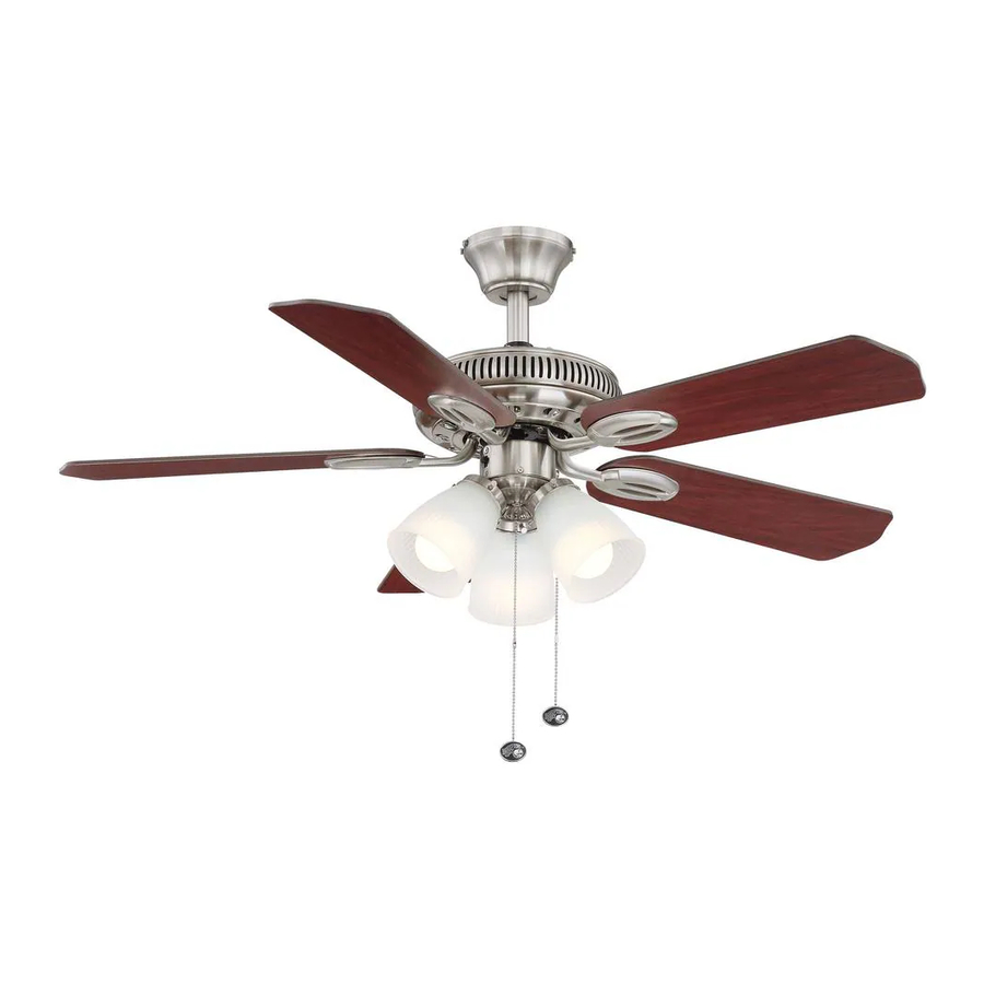
HAMPTON BAY Glendale Owner's Manual
52 in ceiling fan
Hide thumbs
Also See for Glendale:
- Owner's manual (17 pages) ,
- Use and care manual (21 pages) ,
- Use and care manual (20 pages)

Related Manuals for HAMPTON BAY Glendale


Summary of Contents for HAMPTON BAY Glendale
-
Page 1: Ceiling Fan
165 474 Glendale Ceiling Fan Owner’s Manual Glendale Ventilador de Techo de 1,32 Manual del Propietario... -
Page 2: Table Of Contents
52” Glendale Thank you for purchasing our ceiling fan. This product has been manufactured with the highest standards of safety and quality. Ceiling Fan by Hampton Bay Date Purchased Table of Contents Store Purchased Safety Rules ....1 165-474 UL Model No. -
Page 3: Safety Rules
Safety Rules – Read and Save These Instructions To reduce the risk of electric shock, insure electricity has been turned off After making electrical connections, spliced conductors should be turned at the circuit breaker or fuse box before beginning. upward and pushed carefully up into outlet box. The wires should be spread apart with the grounded conductor and the equipment-grounding All wiring must be in accordance with the National Electrical Code conductor on one side of the outlet box and ungrounded conductor on the... -
Page 4: Unpacking Your Fan
Unpacking Your Fan Unpack your fan and check the contents. You should have the following items: Set of blades (5) Light kit Blade Attachment Hardware (16 Screws with Fiber Washers) Canopy assembly Glass shades (3) Ball/downrod assembly 13 Watt compact fluorescent bulbs (3) Electrical Hardware (3 Plastic Wire Nuts) Fan motor assembly... -
Page 5: Installing Your Fan
Installing Your Fan Provide Strong Support Figures 1~3 are examples of different ways to Tools Required mount the outlet box. Phillips screwdriver, straight slot screwdriver, step ladder and wire cutters. Recessed Ceiling Outlet Box Mounting Plate Figure 3 Mounting Options Outlet Box Note: You may need a longer downrod to If there isn't an existing UL listed mounting box,... -
Page 6: Hanging The Fan
Hanging the Fan Motor Wires Remove the Pin in Locked Canopy Ring Positioon Ball/Downrod REMEMBER to turn off the power. Follow the Assembly steps below to hang your fan properly. Ceiling Canopy NOTE: This ceiling fan is supplied with two types Canopy Ring of hanging assemblies;... -
Page 7: Close-To-Ceiling Mounting
Place the rubber gasket over the remaining Option 2: Screw and Collar three screws, route the wires exiting the top of Lock Washer Close-to-Ceiling Mounting the fan motor through the canopy ring (make (3 Places) sure the slot openings are on top). then proceed Remove the canopy ring from the canopy. -
Page 8: Installing Fan To The Electrical Box
Installing Fan to UL Listed Outlet Box Hook the Electrical Box WARNING 120V Wires TO REDUCE THE RISK OF FIRE, ELECTRIC SHOCK OTHER PERSONAL INJURY. MOUNT FAN ONLY TO AN OUTLET BOX OR SUPPORTING SYSTEM MARKED ACCEPTABLE Groove Ceiling Mounting FOR FAN SUPPORT AND USE THE MOUNTING SCREWS PROVIDED WITH THE OUTLET BOX. - Page 9 Connect the fan motor black wire to the supply Making the Electrical SUPPLY CIRCUIT black (hot) wire using a wire nut (Figure 13). Connections Connect the blue wire for light kit to the black Ground household supply wire. REMEMBER to disconnect the power. Conductor Turn wire nut connections upward, spreading If you feel you do not have enough electrical...
-
Page 10: Standard Ceiling Mounting
Close-to-Ceiling Mounting Finishing the Fan Outlet Box Installation Remove the fan from the hook on the hanger bracket. Secure the canopy to the hanger bracket Standard Ceiling Mounting with four screws included with your fan. (Fig. 15) Hanger Raise up canopy ring and line up the 4 tabs with Screws Bracket WARNING... -
Page 11: Attaching The Fan Blades
Attaching the Fan Blades Motor CAUTION MOTOR IS SHIPPED WITH RUBBER MOTOR STOPS TO PREVENT MOVEMENT DURING TRANSPOR- TATION. REMOVE MOTOR STOPS PRIOR TO ATTACHING BLADE BRACKETS. (FIG. 16) Blade arm Slot Attach blades to blade arms using three screws Rubber Packing Mounts with fiber washers. -
Page 12: Blade Balancing
Blade Balancing The following procedure should correct most fan wobble. Check after each step. Touching Ceiling Check that all blade and blade bracket screws are secure. Most fan wobble problems are caused when blade levels are unequal. Check this level by selecting a point on the ceiling above the tip of one of the blades. -
Page 13: Installing The Light Kit
Installing the Light kit CAUTION NOTE BEFORE STARTING INSTALLATION, DISCON- LIGHT BULBS HAVE NO WARRANTY; CAN BE NECT THE POWER BY TURNING OFF THE PURCHASED AT ANY HOME DEPOT STORE. CIRCUIT BREAKER OR REMOVING THE FUSE AT FUSE BOX. TURNING POWER OFF USING THE FAN SWITCH IS NOT SUFFICIENT TO PREVENT ELECTRIC SHOCK. -
Page 14: Operating Your Fan
Operating Your Fan WARNING LOCKING SLOTS OF CEILING CANOPY ARE Warm weather - (Counter Clockwise Direction) PRVIDED ONLY AS AN AID TO MOUNTING. DO A downward air flow creates a cooling effect as NOT LEAVE FAN ASSEMBLY UNATTENDED UNTIL ALL FOUR CANOPY SCREWS ARE shown in Figure 22. -
Page 15: Care Of Your Fan
Care of Your Fan Troubleshooting PROBLEM SOLUTION Here are some suggestions to help you maintain your fan. Fan will not start Check main and branch circuit fuses or breakers. Because of the fan's natural movement, some Check line wire connections to the fan and switch wire connections may become loose. -
Page 16: Specifications
Specifications FAN SIZE SPEED VOLTS AMPS WATTS N.W. G.W. C.F. 0.21 1800 8.5 kgs 9.2 kgs 52” MED. 0.38 3700 1.71’ (18.7 Ibs) (20.2 Ibs) HIGH 0.51 5450 These are approximate measures. They do not include Amps and Wattage used by the light kit . -
Page 17: Warranty Information
Lifetime Limited Warranty (lifetime warranty on motor) The Hampton Bay warrants the fan motor to be free from defects in workmanship and material present at time You must present a copy of the original purchase receipt to obtain warranty of shipment from the factory for a period of lifetime after the date of purchase by the original purchaser.
Need help?
Do you have a question about the Glendale and is the answer not in the manual?
Questions and answers