
Subscribe to Our Youtube Channel
Related Manuals for HAMPTON BAY Gazebo II Plus


Summary of Contents for HAMPTON BAY Gazebo II Plus
- Page 1 111 947 Model: 111947 120 V~ 60 Hz 74 W Read and follow all the instructions before using this product. Gazebo II Plus Ceiling Fan Owner’s Manual Gazebo II Plus Ventilador de Techo de 1,32 m Manual del Propietario...
- Page 2 Gazebo II Plus by Hampton Bay ®...
- Page 3 VENTILADOR DE TECHO/CEILING FAN Marca/Brand: HAMPTON BAY Modelo/Model: 111947 120 V~ 60 Hz 74 W Consumo de energía por unidad de tiempo en operación (Energy Consumption): 71.733 Wh Importador/Importer: SERVICIOS HOME DEPOT, S. DE R.L. DE C.V. Ricardo Margain 605, Santa Engracia, San Pedro Garza García, Nuevo León, C.P.
-
Page 4: Table Of Contents
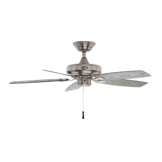
52” Gazebo II Plus Thank you for purchasing our ceiling fan. This product has been manufactured with the highest standards of safety and quality. Ceiling Fan by Hampton Bay Date Purchased Table of Contents Store Purchased Safety Rules ....1 111-947 Unpacking Your Fan . -
Page 5: Safety Rules
Safety Rules - Read and Save These Instructions To reduce the risk of electric shock, insure electricity has been turned off After making electrical connections, spliced conductors should be turned at the circuit breaker or fuse box before beginning. upward and pushed carefully up into outlet box. The wires should be spread apart with the grounded conductor and the equipment-grounding All wiring must be in accordance with the National Electrical Code conductor on one side of the outlet box and ungrounded conductor on the... -
Page 6: Unpacking Your Fan
Unpacking Your Fan Unpack your fan and check the contents. You should have the following items: Set of blades (5) Blades arms (5) Blade Attachment Hardware (16 Screws with Rubber Washers) Canopy assembly 21 Watt LED Light kit Ball/downrod assembly Glass shade Electrical Hardware Coupling cover... -
Page 7: Installing Your Fan
Installing Your Fan Provide Strong Support Tools Required Figures 1~3 are examples of different ways to mount the outlet box. Phillips screwdriver, straight slot screwdriver, step ladder and wire cutters. Recessed Ceiling Outlet Box Mounting Plate Mounting Options Figure 3 Outlet Box Note: You may need a longer downrod to If there isn't an existing NOM listed mounting box,... - Page 8 Hanging the Fan Motor Wires Remove the Pin in Locked Canopy Ring Positioon Ball/Downrod REMEMBER to turn off the power. Follow the Assembly steps below to hang your fan properly. NOTE: This ceiling fan is supplied with two types Ceiling Canopy of hanging assemblies;...
- Page 9 NOTE: If a longer downrod is needed, take out Remove the decorative canopy bottom cover Motor the screw located in the hanger ball, lower the Collar Screw and Lock Washer from the canopy by turning the canopy bottom hanger ball and remove the pin, remove all 3 cover counterclockwise.
- Page 10 Installing Fan to NOM Listed Outlet Box the Electrical Box WARNING 120V TO REDUCE THE RISK OF FIRE, ELECTRIC Wires SHOCK OTHER PERSONAL INJURY. MOUNT FAN ONLY TO AN OUTLET BOX OR SUPPORTING SYSTEM MARKED ACCEPTABLE Groove FOR FAN SUPPORT AND USE THE MOUNTING Ceiling Mounting SCREWS PROVIDED WITH THE OUTLET BOX.
- Page 11 Making the Electrical Connect the fan motor black wire to the supply SUPPLY CIRCUIT black (hot) wire using a wire nut. (Figure 13) Connections Connect the blue wire for light kit to the black Ground WARNING household supply wire. Conductor TO AVOID POSSIBLE ELECTRICAL SHOCK, BE Turn wire nut connections upward, spreading SURE ELECTRICITY IS TURNED OFF AT THE...
- Page 12 Finishing the Fan Flushmount Installation Installation Remove the fan from the hook on the mounting Outlet Box bracket. Secure the canopy to the mounting Standard Ceiling Mounting bracket with four screws included with your fan. Ceiling (Fig. 15) Raise up canopy ring and line up the 4 WARNING Screws Mounting...
- Page 13 Attaching the Fan Blades NOTE Motor MOTOR IS SHIPPED WITH RUBBER MOTOR STOPS TO PREVENT MOVEMENT DURING TRANSPORTATION. REMOVE MOTOR STOPS PRIOR TO ATTACHING BLADE BRACKETS. (FIG. 16) Step 1. Attach blades to blade arms using three Rubber packing mounts screws with rubber washers.
- Page 14 Blade Balancing All blades are grouped by weight during assembly. The following procedure should correct most fan wobble. Check after each step. Touching Ceiling Verify that all blades and blade bracket screws are secure (most fan wobble problems are caused by loose parts). Once the fan is properly installed, run the ceiling fan for 10 minutes to let the fan self-adjust.
-
Page 15: Installing The Light Kit
Installing the Light Kit Fan without Light Kit (Optional) NOTE BEFORE STARTING INSTALLATION, DISCON- Disassemble the switch housing cover from the NECT THE POWER BY TURNING OFF THE light kit, you can keep the light kit for future CIRCUIT BREAKER OR REMOVING THE FUSE use. -
Page 16: Operating Your Transmitter
Operating Your Fan Warm weather - (Counter Clockwise Direction) WARNING A downward air flow creates a cooling effect as LOCKING SLOTS OF CEILING CANOPY ARE PROVIDED ONLY AS AN AID TO MOUNTING. shown in Figure 22. This allows you to set your air DO NOT LEAVE FAN ASSEMBLY UNATTENDED conditioner on a higher setting without affecting UNTIL ALL FOUR CANOPY SCREWS ARE... -
Page 17: Care Of Your Fan
Care of Your Fan Troubleshooting PROBLEM SOLUTION Here are some suggestions to help you maintain your fan. Because of the fan's natural movement, some Fan will not start Check main and branch circuit fuses or breakers. Check line wire connections to the fan and switch wire connections in connections may become loose. -
Page 18: Specifications
Specifications FAN SIZE SPEED VOLTS AMPS WATTS N.W. G.W. C.F. 0.22 12.55 45.66 10.62 kg 12.27 kg 52” MED. 2.27’ 0.36 33.52 94.76 (23.36 lbs) (27.06 lbs) HIGH 0.44 52.30 129.86 These are approximate measures. They do not include Amps and Wattage used by the light kit . Importer: SERVICIOS HOME DEPOT, S.
Need help?
Do you have a question about the Gazebo II Plus and is the answer not in the manual?
Questions and answers