Table of Contents
Advertisement
Advertisement
Table of Contents

Related Manuals for HAMPTON BAY EASTVALE


Summary of Contents for HAMPTON BAY EASTVALE
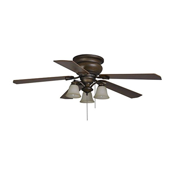
- Page 1 Item #182-596 Model #14413 USE AND CARE GUIDE EASTVALE 52 INCH CEILING FAN Questions, problems, missing parts? Before returning to the store, call Hampton Bay Customer Service 8 a.m. - 6 p.m., EST, Monday-Friday 1-800-527-0998 HAMPTONBAY.COM THANK YOU THANK YOU...
-
Page 2: Table Of Contents
Table of Contents Table of Contents ............Operation ..............Pull Chain Operating Instructions ........... Safety Information ............Reverse Switch Operating Instructions ........Warranty ................. Care and Cleaning ............Pre-installation .............. Troubleshooting ............Specifications ................Tools Required ................. Service Parts ..............Hardware Included .............. -
Page 3: Safety Information
Safety Information □ Read and save these instructions. WARNING: To reduce the risk of electrical shock or fire, do not use this fan with any solid-state fan speed control device. □ To reduce the risk of electric shock, ensure electricity has It will permanently damage the electronic circuitry. -
Page 4: Warranty
Warranty We warrant the fan motor to be free from defects in workmanship and material present at time of shipment from the factory for a period of lifetime after the date of purchase by the original purchaser. We also warrant that all other fan parts, excluding any glass or acrylic blades, to be free from defects in workmanship and material at the time of shipment from the factory for a period of one year after the date of purchase by the original purchaser. -
Page 5: Hardware Included
Pre-Installation (continued) HARDWARE INCLUDED HARDWARE INCLUDED NOTE: Hardware shown to actual size unless noted otherwise in the table below. Part Part Description Description Quantity Quantity Blade attachment hardware (3/16 in.*7.5mm screws+fiber washers) Plastic wire nut Balance kit (not to scale) Nuts (preassembled) Washers (preassembled) Blade arm screws (preassembled) (1/4 in.*1/2mm screws+SWS) -
Page 6: Package Contents
Pre-Installation (continued) PACKAGE CONTENTS PACKAGE CONTENTS Part Part Description Description Quantity Quantity Part Part Description Description Quantity Quantity Mounting bracket Light kit mounting plate Fan motor assembly Switch housing Blades Light kit Blade arms Glass shades Motor housing... -
Page 7: Installation
Installation MOUNTING OPTIONS MOUNTING OPTIONS WARNING: To reduce the risk of fire, electric shock, or personal injury, mount the fan to an outlet box marked acceptable for fan support using the screws provided with the outlet box. An outlet box commonly used for the support of lighting fixtures may not be acceptable for fan support and may need to be replaced. -
Page 8: Assembly
Assembly — Hanging the Fan Hanging the fan motor assembly Attaching the mounting bracket from the mounting bracket to the electrical box □ Place the fan motor assembly (B) onto the hook from WARNING: To reduce the risk of fire, electric shock, or the ceiling mounting bracket (A), and allow it to hang other personal injury, mount the fan only to an outlet box or freely. - Page 9 Assembly — Hanging the Fan (continued) Making the electrical connections WARNING: To avoid possible electrical shock, be sure electricity is turned off at the main fuse box before wiring. WARNING: Check to see that all connections are tight, including the ground, and that no bare wire is visible at the wire nuts (except for the ground wire).
- Page 10 Assembly — Hanging the Fan (continued) Attaching the motor housing Attaching the fan motor assembly to the mounting bracket to the mounting bracket □ □ Move the fan motor assembly (B) into position over Raise the motor housing (E) up against the mounting the four mounting bracket (A) studs and secure with bracket (A).
-
Page 11: Attaching The Fan Blades
Assembly — Attaching the Fan Blades Attaching the blades to the Attaching the blade blade arms assemblies to the motor □ Attach the blades (C) to the blade arms (D) using the WARNING: To reduce the risk of personal injury, do not three blade attachment screws and fiber washers bend the blade arms (D) while installing, balancing the blades (AA). -
Page 12: Installing The Light Kit
Assembly — Installing the Light Kit Attaching the light kit mounting Attaching the light kit to plate to the mounting ring the switch housing □ Remove one of three mounting ring screws (GG) from NOTE: Retain the plug (JJ) to reinsert when not using the the mounting ring (ZZ) and loosen the other two light kit (H). - Page 13 Assembly — Installing the Light Kit (continued) Attaching the light kit assembly Installing the glass shades to the mounting plate and bulbs □ Remove the lock rings (LL) from the sockets by CAUTION: Before starting installation, disconnect the turning the lock rings (LL) clockwise until they unlock. power by turning off the circuit breaker or removing the fuse Insert the glass shades (I) into the glass holders and at the fuse box.
-
Page 14: Operation
Operation PULL CHAIN OPERATING INSTRUCTIONS PULL CHAIN OPERATING INSTRUCTIONS Install two pull chains and fobs (NN) onto the pull chains located in the switch housing (G) and light kit (H). Turn on the power and check the operation of the fan. The 3-speed pull chain controls the fan speed as follows: 1 pull - High, 2 pulls - Medium, 3 pulls - Low, and 4 pulls - Off. -
Page 15: Care And Cleaning
Care and Cleaning Do Do Do not Do not □ □ Check the support connections, brackets, and blade Do not use water when cleaning. Water could damage the attachments twice a year. Make sure they are secure. motor, or the wood, or possibly cause an electrical shock. Because of the fan’s natural movement, some □... -
Page 16: Troubleshooting
Troubleshooting WARNING: Make sure the power is off at the electrical panel box before you attempt any repairs. Refer to the section “Making the Electrical Connections” on page 9. Problem Problem Solution Solution □ Check main and branch circuit fuses or breakers. The fan will not start. -
Page 17: Service Parts
Service Parts Part Part Description Description Part Part Description Description Mounting bracket Nuts (preassembled) Fan motor assembly Washers (preassembled) 5 blades Blade arm screws (1/4 in.*1/2mm screws+SWS) 5 blade arms Mounting ring screws (5/32 in.*8mm screws) Motor housing Nuts (preassembled) Light kit mounting plate Lock washers (preassembled) Switch housing... - Page 18 Questions, problems, missing parts? Before returning to the store, call Hampton Bay Customer Service 8 a.m. - 6 p.m., EST, Monday-Friday 1-800-527-0998 HAMPTONBAY.COM Retain this manual for future use. YG252000001-C...
Need help?
Do you have a question about the EASTVALE and is the answer not in the manual?
Questions and answers