Table of Contents
Advertisement
Quick Links
for Surround
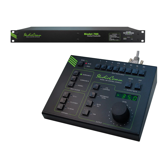
Model 780-01 Central Controller and
Model 790 Control Console
User Guide
Issue 4, December 2020
This User Guide is applicable for systems consisting of:
Model 780-01: serial number M780-01-00151 and later with
software version 1.00 and higher and FPGA version 4.15 and higher;
Model 790: serial number M790-00151 and later with software version 1.00 and higher
© 2020 by Studio Technologies, Inc., all rights reserved
www.studio-tech.com
50390-1220, Issue 4
Advertisement
Table of Contents

Related Manuals for Studio Technologies StudioComm 780-01


Summary of Contents for Studio Technologies StudioComm 780-01
- Page 1 Model 780-01: serial number M780-01-00151 and later with software version 1.00 and higher and FPGA version 4.15 and higher; Model 790: serial number M790-00151 and later with software version 1.00 and higher © 2020 by Studio Technologies, Inc., all rights reserved www.studio-tech.com 50390-1220, Issue 4...
- Page 2 This page intentionally left blank.
-
Page 3: Table Of Contents
Installation ..............9 Configuration ..............16 Operation ..............35 Technical Notes ............41 Specifications ...............45 Appendix A—Connection Pin-Out Charts ..... 47 Appendix B—Sync Input Sources ........ 48 Appendix C—Downmix Formulas ........ 49 Model 780-01/790 User Guide Issue 4, December 2020 Studio Technologies, Inc. Page 3... -
Page 4: Revision History
Revised text for error codes Err1, Err2, and Err3; added text for error code Err4. Issue 2, April 2015: • Revised specifications to reflect final audio performance measurements. • Text clarifications. Issue 1, January 2015: • Initial release. Issue 4, December 2020 Model 780-01/790 User Guide Page 4 Studio Technologies, Inc. -
Page 5: Introduction
(SRC) capability, allowing a the system’s “command center” and is wide range of digital audio sources to be designed to reside at a user’s location, monitored. To compensate with processing Model 780-01/790 User Guide Issue 4, December 2020 Studio Technologies, Inc. Page 5... - Page 6 Figure 2. Model 780-01 Central Controller Back Panel AC mains To/from Digital Sync Stereo Digital surround (7.1) Models 790 & monitor outputs input input inputs A & B 71 Control Consoles Remote control inputs Issue 4, December 2020 Model 780-01/790 User Guide Page 6 Studio Technologies, Inc.
- Page 7 Model 790 or Model 71 Control Con- fader monitor output’s subwoofer (SUB) soles. A second 9-pin “D-sub” connector channel. is used to interface with remote control Model 780-01/790 User Guide Issue 4, December 2020 Studio Technologies, Inc. Page 7...
- Page 8 Multiple channels audio console or other communications can also be simultaneously selected for system can control the level of the post- muting or “soloing.” fader monitor outputs. Issue 4, December 2020 Model 780-01/790 User Guide Page 8 Studio Technologies, Inc.
-
Page 9: Installation
Model 780-01 into the equipment rack helps to ensure proper handling by the using two mounting screws per side. Select Model 780-01’s all-digital signal path. a location that is convenient for making Model 780-01/790 User Guide Issue 4, December 2020 Studio Technologies, Inc. Page 9... - Page 10 8-channel surround a 3-pin female XLR connector for interfac- (7.1) sources, one pre-fader (fixed level) ing with a digital audio source. The mating Issue 4, December 2020 Model 780-01/790 User Guide Page 10 Studio Technologies, Inc.
- Page 11 (DB-25M) on one end and are designed for connection to digital eight 3-pin male XLR connectors on the inputs on audio amplifiers associated with other. monitor loudspeakers. Alternately, they can Model 780-01/790 User Guide Issue 4, December 2020 Studio Technologies, Inc. Page 11...
- Page 12 Issue 4, December 2020 Model 780-01/790 User Guide Page 12 Studio Technologies, Inc.
- Page 13 Model 780-01 Central Controller. This is for the DC connections (pins 4 and 9). This used to interface the unit with Model 790 Model 780-01/790 User Guide Issue 4, December 2020 Studio Technologies, Inc. Page 13...
- Page 14 3 V or less it 790 or Model 71 units. should function correctly. If it’s greater than 3 V the cable is too long or the wire gauge is too small. Issue 4, December 2020 Model 780-01/790 User Guide Page 14 Studio Technologies, Inc.
- Page 15 Refer to the Technical Notes a few seconds initial system operation will section of this user guide for details. commence and the two LEDs will perform Model 780-01/790 User Guide Issue 4, December 2020 Studio Technologies, Inc. Page 15...
-
Page 16: Configuration
• Sync Input Termination settings and reflect changes as they are • Audio-Synced-to-Video Sample Rate being made. • Reference Level Issue 4, December 2020 Model 780-01/790 User Guide Page 16 Studio Technologies, Inc. - Page 17 Model 71. All other configuration param- By default SRC is enabled and it’s recom- eters are stored in the Model 780-01. mended that it remains that way. However Model 780-01/790 User Guide Issue 4, December 2020 Studio Technologies, Inc. Page 17...
- Page 18 BNC connector. The fourth choice al- the application. The StudioComm system lows the L/R input of the currently selected allows a precise post-fader monitor output Issue 4, December 2020 Model 780-01/790 User Guide Page 18 Studio Technologies, Inc.
- Page 19 0.0. As the rotary control is turned in new reference level. The value shown the counterclockwise direction the display Model 780-01/790 User Guide Issue 4, December 2020 Studio Technologies, Inc. Page 19...
- Page 20 82 dB and 87 dB, are well within tions a configuration mode allows the LFE the allowable range. channel to be included. In this scenario, Issue 4, December 2020 Model 780-01/790 User Guide Page 20 Studio Technologies, Inc.
- Page 21 A configured delay time to the nominal output level. In most cases is referenced to a sample rate of 48 kHz. Model 780-01/790 User Guide Issue 4, December 2020 Studio Technologies, Inc. Page 21...
- Page 22 SPL meter and a Figure 8. Model 71 Control Console Front and calibrated signal source. This is a hassle Back Panels you may not need! Issue 4, December 2020 Model 780-01/790 User Guide Page 22 Studio Technologies, Inc.
- Page 23 Reference Level LED selected configuration parameters will be stored in a nonvolatile memory device that is located inside this specific Model 71. Figure 9. Model 71 Device Address Chart Model 780-01/790 User Guide Issue 4, December 2020 Studio Technologies, Inc. Page 23...
- Page 24 Press and hold the configuration button for 2 seconds to enter or exit the configuration mode. These LEDs will light alternately when configuration mode is ac- Issue 4, December 2020 Model 780-01/790 User Guide Page 24 Studio Technologies, Inc.
- Page 25 Stereo input sample rate converter enabled. Note: The Model 790’s device address is the only parameter stored in the Model 790. All other parameters are stored in the Model 780-01. Model 780-01/790 User Guide Issue 4, December 2020 Studio Technologies, Inc. Page 25...
- Page 26 80 Hz. Default: Bass management disabled. Bass management low-pass filter slope 24 dB-per-octave. Bass management high-pass filter slope 24 dB-per-octave. Bass management crossover frequency 80 Hz. Issue 4, December 2020 Model 780-01/790 User Guide Page 26 Studio Technologies, Inc.
- Page 27 Available sample rates are 44.1, 48, 88.2, and 96 kHz. Default: Sync source is L/R of currently selected input. Sync input terminated. Audio-synced-to-video sample rate 48 kHz. Model 780-01/790 User Guide Issue 4, December 2020 Studio Technologies, Inc. Page 27...
- Page 28 The 5-second button-press delay is a safety feature ensuring that the reference level will not be accidently changed. To permanently store the new value, you must still exit the configuration mode. Issue 4, December 2020 Model 780-01/790 User Guide Page 28 Studio Technologies, Inc.
- Page 29 SPL, and auto reference level in dB SPL. reference level off. Default: Attenuation display mode selected. 85.0 dB SPL reference level. Auto ref level off disabled. Model 780-01/790 User Guide Issue 4, December 2020 Studio Technologies, Inc. Page 29...
- Page 30 Press and hold the Dim button to display and select the dim level, remote mute all, and remote dim. Default: 20 dB dim level. Remote mute all enabled. Remote dim enabled. Issue 4, December 2020 Model 780-01/790 User Guide Page 30 Studio Technologies, Inc.
- Page 31 LFE downmix level and pre-fader monitor output mode. Default: LFE downmix level full attenuation when To Stereo or To Mono downmix functions active. Pre-fader monitor outputs pre-downmix. Model 780-01/790 User Guide Issue 4, December 2020 Studio Technologies, Inc. Page 31...
- Page 32 48 kHz sampling rate. The value is scaled up or down for other sample rates. Default: Input delay 0 milliseconds for both A and B. Issue 4, December 2020 Model 780-01/790 User Guide Page 32 Studio Technologies, Inc.
- Page 33 Use the level control to adjust the post-fad- er monitor output level offsets. The range is –12.0 to 12.0 in 0.5-dB steps. Default: 0.0 dB post-fader monitor output level offsets. Model 780-01/790 User Guide Issue 4, December 2020 Studio Technologies, Inc. Page 33...
- Page 34 Model 790 to device address A1. If another connected unit is already configured for address A1, normal system operation will stop. Note: The 5-second button-press delay is a safety feature ensuring that the factory defaults will not be accidently restored. Issue 4, December 2020 Model 780-01/790 User Guide Page 34 Studio Technologies, Inc.
-
Page 35: Operation
(SL), surround right (SR), and subwoofer (sync) reference or the L/R input of the se- (SUB) monitor output channels. The To lected input source. Stereo downmix function allows a 7.1 Model 780-01/790 User Guide Issue 4, December 2020 Studio Technologies, Inc. Page 35... - Page 36 The LED associated with meet the requirements of the specific moni- the mute all button will light whenever toring environment. The LED associated Issue 4, December 2020 Model 780-01/790 User Guide Page 36 Studio Technologies, Inc.
- Page 37 Model 780-01/790 User Guide Issue 4, December 2020 Studio Technologies, Inc. Page 37...
- Page 38 These serve as an aid in observing four dashes (– – – –). the performance of the loudspeaker system. Issue 4, December 2020 Model 780-01/790 User Guide Page 38 Studio Technologies, Inc.
- Page 39 If the Model 790 is configured to display used to select and display the input delay. the monitor output level in dB SPL, the When the mute/solo button is pressed and Model 780-01/790 User Guide Issue 4, December 2020 Studio Technologies, Inc. Page 39...
- Page 40 LEDs for control and As previously discussed in the Installation status display. The rotary level control section of this user guide, two remote con- Issue 4, December 2020 Model 780-01/790 User Guide Page 40 Studio Technologies, Inc.
-
Page 41: Technical Notes
On occur. The LED will continue to display the the Model 780-01 the sync status LED will Model 780-01/790 User Guide Issue 4, December 2020 Studio Technologies, Inc. Page 41... - Page 42 Model 780-01. The most likely cause with an indication that a power loss is would be incorrect wiring of the data pair imminent. When this condition is detected linking the two units. Issue 4, December 2020 Model 780-01/790 User Guide Page 42 Studio Technologies, Inc.
- Page 43 Model tions all signals will have a sample rate 780-01’s internal timing. While it would be of 48 kHz. A Model 780-01 and all of its Model 780-01/790 User Guide Issue 4, December 2020 Studio Technologies, Inc. Page 43...
- Page 44 (FPGA) and then on to the digital audio transmitter (DIT) integrated circuits. This is provided for future use and is not active at this time. Issue 4, December 2020 Model 780-01/790 User Guide Page 44 Studio Technologies, Inc.
-
Page 45: Specifications
Weight: 3.6 pounds (1.6 kg) Dynamic Range: >135 dB Type: balanced AES3 (110 ohms, 5 Vpp) Connector: 25-pin female D-subminiature (DB- 25F), AES59-2012-compliant Model 780-01/790 User Guide Issue 4, December 2020 Studio Technologies, Inc. Page 45... - Page 46 4.10 inches deep (10.4 cm) Weight: 1.7 pounds (0.8 kg) Weight: 0.8 pounds (0.4 kg) Specifications and information contained in this User Guide subject to change without notice. Issue 4, December 2020 Model 780-01/790 User Guide Page 46 Studio Technologies, Inc.
-
Page 47: Appendix A-Connection Pin-Out Charts
D-subminiature (DE-9F). Connector uses 4-40 threaded inserts for locking with mating plug. Connections between Model 780-01 and Model 790 and Model 71 Connections for Remote Control Inputs Model 780-01/790 User Guide Issue 4, December 2020 Studio Technologies, Inc. Page 47... -
Page 48: Appendix B-Sync Input Sources
720p/23.98 Hz 1080p/24 Hz 720p/24 Hz 1080p/25 Hz 720p/25 Hz 1080p/29.97 Hz 720p/29.97 Hz 1080p/30 Hz 720p/30 Hz 1080psf/24 Hz 720p/50 Hz 1080psf/23.98 Hz 720p/59.94 Hz 720p/60 Hz Issue 4, December 2020 Model 780-01/790 User Guide Page 48 Studio Technologies, Inc. -
Page 49: Appendix C-Downmix Formulas
L, R, LFE, SL, SR, BL, and BR mute For Stereo Input C = 0.707L + 0.707R L and R mute (LFE, SL, SR, BL, and BR already muted) Model 780-01/790 User Guide Issue 4, December 2020 Studio Technologies, Inc. Page 49...
Need help?
Do you have a question about the StudioComm 780-01 and is the answer not in the manual?
Questions and answers