Advertisement
Quick Links
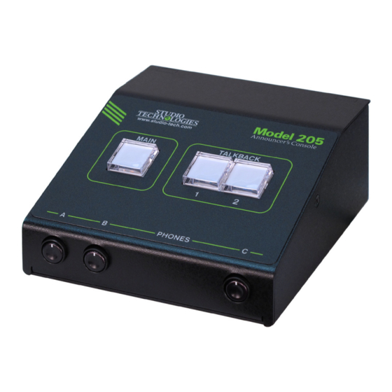
Model 205 Announcer's Console
User Guide
Issue 2, October 2018
This User Guide is applicable for serial numbers
M205-00151 to 00500 with application firmware 1.2 and later
and STcontroller application version 1.07.00 and later.
Copyright © 2018 by Studio Technologies, Inc., all rights reserved
www.studio-tech.com
50641-1018, Issue 2
Advertisement

Related Manuals for Studio Technologies 205


Summary of Contents for Studio Technologies 205
- Page 1 Issue 2, October 2018 This User Guide is applicable for serial numbers M205-00151 to 00500 with application firmware 1.2 and later and STcontroller application version 1.07.00 and later. Copyright © 2018 by Studio Technologies, Inc., all rights reserved www.studio-tech.com 50641-1018, Issue 2...
- Page 2 This page intentionally left blank.
-
Page 3: Table Of Contents
Revision History ............4 Introduction ..............5 Getting Started ............. 10 Operation ..............19 Technical Notes ............24 Specifications ............... 28 Appendix A: Model 205 Block Diagram ......29 Model 205 User Guide Issue 2, October 2018 Studio Technologies, Inc. Page 3... -
Page 4: Revision History
Revision History Issue 2, October 2018: • Documents addition of the Push to Mute/Tap to Latch main button operating mode. Issue 1, April 2018: • Initial release. Issue 2, October 2018 Model 205 User Guide Page 4 Studio Technologies, Inc. -
Page 5: Introduction
Applications and streaming broadcast applications. The unit is housed in a compact, rugged The Model 205 on its own can provide an steel enclosure that’s intended for table- “all-Dante” solution for one on-air talent top use. Calling the Model 205 “cute” or location. - Page 6 And with Set up, configuration, and operation of the two talkback audio channels available the Model 205 is simple. An etherCON® as Dante output channels, routing to inputs RJ45 jack is used to interconnect with a...
- Page 7 Ethernet Data and PoE AES67 interoperability standard. In this mode the three transmitter (output) chan- The Model 205 connects to a local area nels will function in multicast; unicast is not network (LAN) by way of a standard supported. In addition, the unit is compat- 100 Mb/s twisted-pair Ethernet interface.
- Page 8 The Model 205 provides two remote con- Configuration Flexibility trol inputs. Configuration choices allow The Model 205 can be configured to meet these to be assigned to work in parallel the needs of specific applications and user with the main, talkback 1, or talkback 2 preferences.
- Page 9 Model as it is routed to the left and right chan- 205 by way of Dante inputs 1 and 2 and nels of the headphone output. This ste- is routed in stereo to the left and right reo pair enters the unit by way of Dante channels of the headphone output.
-
Page 10: Getting Started
ANNOUNCER’S CONSOLE Three system modes select the overall An Ethernet data connection with Power- way in which the Model 205 functions. The over-Ethernet (PoE) capability will be on-air mode is optimized for applications made using either a standard RJ45 patch... - Page 11 This could be connected to the current draw. To prevent this undesirable Model 205 by way of the microphone output condition ensure that no input audio signal connector. This would not create a problem...
- Page 12 Refer to Appendix A for a in this guide. A 3.5 mm 3-conductor jack block diagram of the microphone input and is located on the Model 205’s back panel microphone output circuitry. and provides access to the two remote The microphone output can be connected control inputs.
- Page 13 4-output integrated circuit to implement KHz will be appropriate. While technically the Dante functionality. The Model 205 the Model 205 can serve as a clock master can also be configured to meet the re- for a Dante network (as can all Dante- quirements of the AES67 standard.
- Page 14 Windows operating systems that are compressor active LED, orange in color version 7 and later. STcontroller versions and visible on the back of the Model 205’s 1.07.00 and later will fully support the Mod- enclosure adjacent to the microphone el 205. If required, download and install...
- Page 15 B adjusts its level. A stereo pair can a single potentiometer to simultaneously enter the Model 205 by way of Dante input adjust the level of a stereo pair while channels 3 and 4. These signals, whose...
- Page 16 B. A stereo pair can cause the associated signal to fully mute. enter the Model 205 by way of Dante input Selecting the full mute mode may be ap- channels 3 and 4. These signals will be...
- Page 17 • Push to Mute: If this mode is selected tive-to-inactive. Upon Model 205 power the main button function will normally up the main button will be in its inactive be active and its green LED lit.
- Page 18 LED will change The system mode configures the overall from green to red. It will stay in this con- manner in which the Model 205 operates. dition until the main button is released. Specifically, it determines how the Dante...
-
Page 19: Operation
LEDs, one red and one green. When enabled equipment. they light and with what color depends on the configuration of the Model 205 and the Initial Operation current operating condition. The intensity of these LEDs can be adjusted to meet the... - Page 20 Functions within the Dante Controller and received. It will slowly flash green when STcontroller software applications allow this specific Model 205 is part of a Dante a specific Model 205 unit to be identified. network and is serving as the clock mas- Each application provides an “eyeball”...
- Page 21 Dante that’s located on the back panel of the main output channel and the microphone Model 205. How the button functions will output connector will alternate between depend on the configuration choice that the active and muted states whenever has been made using STcontroller.
- Page 22 MODEL 205 ANNOUNCER’S CONSOLE Model 205 power up the audio signal will • Latching: If this mode is selected the be in its muted state. audio signal associated with a Dante talkback output channel will alternate be- • Push to Talk/Tap to Latch: This mode is...
- Page 23 (reduced in level or attenuated) is used to select the overall operating mode by 18 dB whenever one of the main or of the Model 205. Specifically, the system talkback functions are active. In this way operating mode determines how the main the headphone output can be connected function will operate vis-à-vis the talkback...
-
Page 24: Technical Notes
DHCP (Dynamic Host Configura- its specific static IP address. If knowledge tion Protocol). If a DHCP server is not of a Model 205’s IP address has been detected an IP address will automatically misplaced there is no reset button or other be assigned using the link-local protocol. - Page 25 The green host function that directly supports connec- LED associated with the main button will tion of a USB flash drive. The Model 205’s “flash” to display the major version number. MCU updates its firmware using a file Then the red LED associated with talkback named m205.bin.
- Page 26 While the firmware file inside of the zip connector. file will adhere to the naming convention 4. Apply power to the Model 205 by con- required by the Model 205, the name of necting to a Power-over-Ethernet (PoE) the zip file itself will include the file’s ver- Ethernet source.
- Page 27 Model 205’s defaults applied to the Model 205. Upon power up to be reset to the factory values. From the main button’s LED will flash on and off...
-
Page 28: Specifications
Impedance: 3.1 k ohms, nominal Ethernet: Neutrik etherCON RJ45 Gain: 35, 43, 52, 59 dB, selectable USB: type A receptacle (located inside Model 205’s Frequency Response: 25 Hz to 20 kHz, –3 dB enclosure and used only for updating firmware) Distortion (THD+N): <0.018%, measured at 35 dB... -
Page 29: Appendix A: Model 205 Block Diagram
MODEL 205 ANNOUNCER’S CONSOLE Appendix A: Model 205 Block Diagram The following block diagram shows a simplified version of the Model 205’s microphone input and microphone output circuitry. Model 205 User Guide Issue 2, October 2018 Studio Technologies, Inc. Page 29...
Need help?
Do you have a question about the 205 and is the answer not in the manual?
Questions and answers