Planet GS-5220-24P4X Quick Installation Manual
Gs-5220 poe series, l2 plus managed poe switch
Hide thumbs
Also See for GS-5220-24P4X:
- Command manual (433 pages) ,
- Quick installation manual (16 pages)
Table of Contents
Advertisement
Quick Links
Advertisement
Table of Contents

Related Manuals for Planet GS-5220-24P4X


Summary of Contents for Planet GS-5220-24P4X
- Page 1 L2+ Managed PoE Switch GS-5220 PoE Series Quick Installation Guide...
-
Page 2: Table Of Contents
Table of Contents 1. Package Contents ..................3 2. Requirements ..................... 5 3. Terminal Setup ................... 6 4. Logon to Console ..................7 5. Configuring IP Address ................8 6. Starting Web Management .................10 7. Saving Configuration ..................13 8. Recovering Back to Default Configuration .............14 9. Customer Support ..................15... -
Page 3: Package Contents
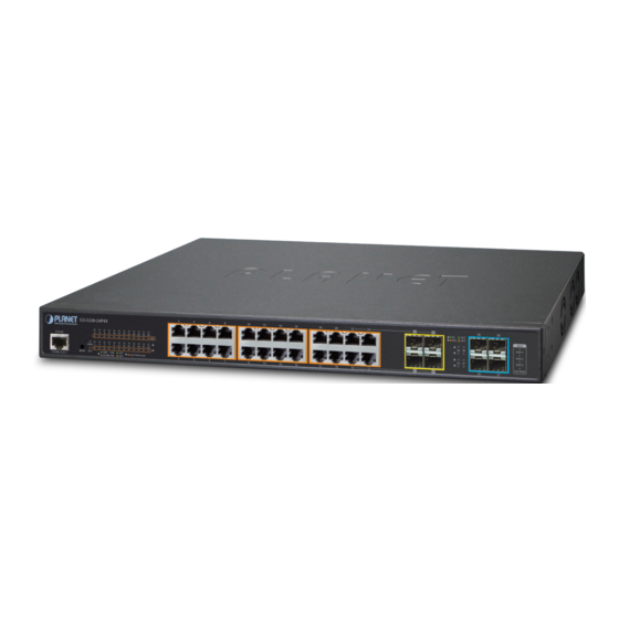
1. Package Contents Thank you for purchasing PLANET GS-5220 Series Managed PoE Switch. The description of this model is shown below: Gigabit 10G System Gigabit SFP Model Name RJ45 SFP+ Power Redundant Slots Ports Slots Budget Power GS-5220-24P4X 4 combo 400W GS-5220-24P4XR 4 combo 400W GS-5220-24PL4X 4 combo... - Page 4 The Managed PoE Switch z Quick Installation Guide z RJ45 to RS232 Cable z Rubber Feet z Two Rack-mounting Brackets with Attachment Screws z Power Cord z SFP Dust-proof Caps Model SFP Dust-proof Caps GS-5220-24P4X GS-5220-24P4XR GS-5220-24PL4X GS-5220-24PL4XR GS-5220-48P4X GS-5220-48P4XR GS-5220-48PL4X GS-5220-48PL4XR If any item is found missing or damaged, please contact your local reseller for...
-
Page 5: Requirements
2. Requirements z Workstations running Windows 10/XP/2003/Vista/7/8/2008, MAC OS X or later, Linux, UNIX, or other platforms are compatible with TCP/IP protocols. z Workstations are installed with Ethernet NIC (Network Interface Card) z Serial Port Connection (Terminal) The above Workstations come with COM Port (DB9) or USB-to-RS232 converter. The above Workstations have been installed with terminal emulator, such as Hyper Terminal included in Windows XP/2003. Serial cable -- one end is attached to the RS232 serial port, while the other end to the console port of the Managed PoE Switch. -
Page 6: Terminal Setup
3. Terminal Setup To configure the system, connect a serial cable to a COM port on a PC or notebook computer and to RJ45 type of serial port of the Managed Switch. PC / Workstation with Terminal Emulation Software Managed Switch RS232 to RJ45 Cable Serial Port RJ45 Console Port Figure 3-1 Managed Switch Console Connectivity A terminal program is required to make the software connection to the Managed Switch. -
Page 7: Logon To Console
4. Logon to Console Once the terminal is connected to the device, power on the Managed Switch, and the terminal will display “running testing procedures”. Then, the following message asks to log in user name and password. The factory default user name and password are shown as follows and the login screen in Figure 4-1 appears. -
Page 8: Configuring Ip Address
5. Configuring IP Address The Managed PoE Switch is shipped with default IP address shown below. IP Address: 192.168.0.100 Subnet Mask: 255.255.255.0 To check the current IP address or modify a new IP address for the Switch, please use the procedures as follows: Show the current IP Address 1. At the “#” prompt, enter “show ip interface brief”. 2. The screen displays the current IP address as shown in Figure 5-1. Figure 5-1: IP Information Screen Configuring IP Address 3. At the “#” prompt, enter the following command and press <Enter> as shown in Figure 5-2. - Page 9 Store current switch configuration 5. At the “#” prompt, enter the following command and press <Enter>. # copy running-config startup-config Figure 5-3: Saving Current Configuration Command Screen If the IP is successfully configured, the Managed Switch will apply the new IP address setting immediately. You can access the Web interface of the Managed Switch through the new IP address.
-
Page 10: Starting Web Management
6. Starting Web Management The following shows how to start up the Web Management of the Managed Switch. Note the Managed Switch is configured through an Ethernet connection. Please make sure the manager PC must be set to the same IP subnet address. For example, the default IP address of the Managed Switch is 192.168.0.100, then the manager PC should be set to 192.168.0.x (where x is a number between 1 and 254, except 100), and the default subnet mask is 255.255.255.0. - Page 11 Default IP Address: 192.168.0.100 Default Username: admin Default Password: admin Figure 6-2: Login Screen 3. After entering the password, the main screen appears as Figure 6-3 shows. Figure 6-3: Web Main Screen of Managed Switch...
- Page 12 The Switch Menu on the left of the Web page lets you access all the commands and statistics the Managed PoE Switch provides. Figure 6-4: Switch Menu If you are not familiar with Switch functions or the related param- eter, press “Help icon” anytime on the Web page to get the help description.
-
Page 13: Saving Configuration
7. Saving Configuration In the Managed Switch, the running configuration file stores in the RAM. In the current version, the running configuration sequence of running-config can be saved from the RAM to FLASH by executing save startup config command, so that the running configuration sequence becomes the startup configuration file, which is called configuration save. -
Page 14: Recovering Back To Default Configuration
10 seconds. After the device is rebooted, you can log in the management Web interface within the same subnet of 192.168.0.xx. RESET 1000 at/af PoE In-use 10/100 Figure 8-1: GS-5220-24P4X(R) Reset Button... -
Page 15: Customer Support
(Please select your switch model name from the drop-down menu of Product Model.) Copyright © PLANET Technology Corp. 2017. Contents are subject to revision without prior notice. PLANET is a registered trademark of PLANET Technology Corp. All other trademarks belong to their respective owners.
Need help?
Do you have a question about the GS-5220-24P4X and is the answer not in the manual?
Questions and answers