Advertisement
Quick Links
Please note that Cypress is an Infineon Technologies Company.
The document following this cover page is marked as "Cypress" document as this is the
company that originally developed the product. Please note that Infineon will continue
to offer the product to new and existing customers as part of the Infineon product
portfolio.
Continuity of document content
The fact that Infineon offers the following product as part of the Infineon product
portfolio does not lead to any changes to this document. Future revisions will occur
when appropriate, and any changes will be set out on the document history page.
Continuity of ordering part numbers
Infineon continues to support existing part numbers. Please continue to use the
ordering part numbers listed in the datasheet for ordering.
www.infineon.com
Advertisement

Related Manuals for Infineon Traveo II CPU board


Summary of Contents for Infineon Traveo II CPU board
- Page 1 The document following this cover page is marked as “Cypress” document as this is the company that originally developed the product. Please note that Infineon will continue to offer the product to new and existing customers as part of the Infineon product portfolio.
- Page 2 CYTVII-B-E-100-SO board quick start guide Traveo™ II CPU board Kit contents: 1. Traveo™ II CPU board (CYTVII-B-E-100-SO) 2. Mini-B USB cable 3. 12-V universal power adapter 4. Quick start guide (this document) 5. Screws and spacers...
- Page 3 CYTVII-B-E-100-SO board quick start guide Traveo™ II CPU board • • Ensure that jumpers J23 (pins 1 & 2), J5, J6, J7, J9, J10 Insert the Traveo™ II device into the IC socket (U3). are shorted. Connect the 12-V adapter to the power jack (J3). Align Pin 1 with the arrow mark near C16 and close the socket cover.
- Page 4 CYTVII-B-E-100-SO board quick start guide Traveo™ II CPU board Instructions: Use the board in conjunction with the body controller baseboard (CYTVII-B-E-BB) to evaluate all features of the Traveo™ II MCU. In standalone mode, only limited features of the MCU are available. See the CPU board user guide for details.
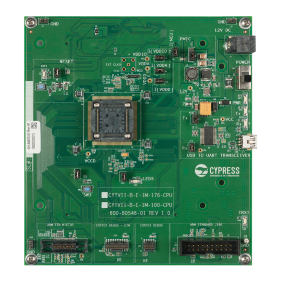
- Page 5 CYTVII-B-E-100-SO board quick start guide Traveo™ II CPU board Traveo™ II CPU board details 16. GND test probe point – TP8 1. Jumper for GND probe – J2 17. IDC Arm® standard JTAG 20-pin connector – J20 2. Power connector 12V – J3 18.