Table of Contents
Advertisement
Professional Shop Manual
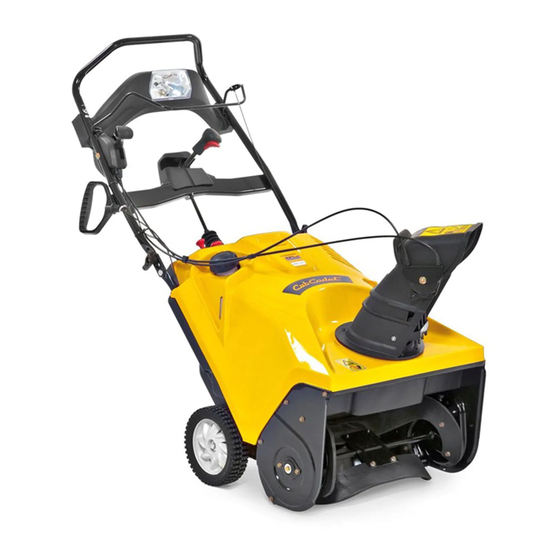
221 HP/LHP Snow Throwers
NOTE: These materials are for use by trained technicians who are experienced in the service and repair of outdoor power
equipment of the kind described in this publication, and are not intended for use by untrained or inexperienced individuals.
These materials are intended to provide supplemental information to assist the trained technician. Untrained or inexperi-
enced individuals should seek the assistance of an experienced and trained professional. Read, understand, and follow all
instructions and use common sense when working on power equipment. This includes the contents of the product's Oper-
ators Manual, supplied with the equipment. No liability can be accepted for any inaccuracies or omission in this publication,
although care has been taken to make it as complete and accurate as possible at the time of publication. However, due to
the variety of outdoor power equipment and continuing product changes that occur over time, updates will be made to these
instructions from time to time. Therefore, it may be necessary to obtain the latest materials before servicing or repairing a
product. The company reserves the right to make changes at any time to this publication without prior notice and without
incurring an obligation to make such changes to previously published versions. Instructions, photographs and illustrations
used in this publication are for reference use only and may not depict actual model and component parts.
© Copyright 2011 MTD Products Inc. All Rights Reserved
Advertisement
Table of Contents

Related Manuals for MTD Cub Cadet 221 HP


Summary of Contents for MTD Cub Cadet 221 HP
- Page 1 Instructions, photographs and illustrations used in this publication are for reference use only and may not depict actual model and component parts. © Copyright 2011 MTD Products Inc. All Rights Reserved...
-
Page 3: Table Of Contents
Table of Contents Chapter 1: Introduction ......................1 Professional Service Manual Intent ........1 Safety . -
Page 5: Chapter 1: Introduction
• Common sense in operation and safety is assumed. • In no event shall MTD or Cub Cadet be liable for poor text interpretation or poor execution of the proce- dures described in the text. • If the person using this manual is uncomfortable with any procedures they encounter, they should seek the help of a qualified technician or Cub Cadet Technical Support. - Page 6 221 HP/LHP • Be prepared in case of emergency: ! CAUTION ! CAUTION Keep a fire extinguisher nearby Keep a first aid kit nearby Keep emergency contact numbers handy • Replace any missing or damaged safety labels on shop equipment. •...
-
Page 7: Fasteners
Introduction Fasteners • Most of the fasteners used on these snow throwers have SAE thread sizes.The engines have metric thread sizes. For this reason, wrench sizes are frequently identified in the text, and measurements are given in U.S. and metric scales. •... -
Page 8: Understanding Model And Serial Numbers
31AM2T6D710. This manual is likely to carry useful information for a range of similar snow throwers that may carry a variety of MTD and private brand names. Figure 1.2 The break down of what the model number means is as fol- lows: •... -
Page 9: Chapter 2: Engine
Remove the spark plug using a 13/16” or 21mm wrench. NOTE: A flexible coupling or “wobbly” extension may help. NOTE: MTD does not recommend cleaning spark plugs. Use of a wire brush may leave metal deposits on the insulator that causes the spark plug to short out and fail to spark. -
Page 10: Oil Change
This corrodes the metal components of the fuel system, especially the carburetor. Alco- hol also does not produce as much heat as gasoline when burnt. This results in less power for the engine. A 10% alcohol mix (E10) is acceptable for MTD engines. Anything higher than that will result in performance issues. -
Page 11: Valve Lash
Engine Valve lash NOTE: Valve lash is the clearance between the top of the valve stem and the rocker arm. The valve lash should be checked after the first 25 hours of use and every 100 hours after that. Valve lash can be Spark plug checked and adjusted using the following steps: If the engine has been run, allow it to cool thoroughly. - Page 12 221 HP/LHP .004” feeler gauge Check valve lash between each valve stem and rocker arm using a feeler gauge. Intake valve lash (carburetor side) should be 0.003”- 0.005” (0.10 + 0.02mm). See Figure 2.6. Figure 2.6 .006” feeler Exhaust valve lash (muffler side) should be 0.005- gauge 0.007”...
-
Page 13: Rear Engine Cover
Engine Rear engine cover The engine on this series of snow throw is fully enclosed. The rear engine cove can easily be removed to preform many engine repair or maintenance procedures such as: • changing the oil • servicing the carburetor •... -
Page 14: Top Engine Cover
221 HP/LHP Top engine cover Most of the common engine repair procedures can be performed by removing the rear engine cover. Reaching some engine parts require removing the top engine cover. These parts include: • Recoil starter • Flywheel • Ignition coil To remove the top engine cover: Drain the fuel from the fuel tank (indicated by the... - Page 15 Engine Disconnect the primer hose. See Figure 2.12. Disconnect the harness that connects to the safety switch. Primer hose Safety switch Figure 2.12 NOTE: If equipped with remote chute control: Remove the nut and bolt (indicated by the arrow in Figure 2.13.) that attach the universal joint to the chute rotation rod using a #2 phillips screw driver and a 5/16”...
- Page 16 221 HP/LHP Remove the three screws (indicated by the arrows in Figure 2.15.) that hold the lower chute to the rotating ring gear using a 5/16” wrench. With the cables still attached, swing the chute to the side Figure 2.15 Remove the two screws indicated by the arrow in Figure 2.16.(one on each side) that secure the cover to the handle bar.
-
Page 17: Fuel Tank
Engine Fuel tank To remove/replace the fuel tank: Gasoline is extremely flammable and ! W A R N IN G ! W A R N IN G the vapors are explosive. Avoid all sources of heat when working on the fuel system. -
Page 18: Engine Removal
221 HP/LHP Engine removal The design of the 221 series snow throwers provides enough engine access to perform most repair procedures; however, occasionally the engine may need to be removed. Some of the repair procedures that require engine removal are: •... - Page 19 Engine Disconnect the ground wire (indicated by the arrows in Figure 2.22.) from the engine block using a 10 mm wrench. Figure 2.22 Remove the two engine mounting screws (indicated by the arrows in Figure 2.23.) from the under side of the snow thrower using a 1/2”...
-
Page 20: Maintenance Charts
221 HP/LHP Maintenance charts Engine Maintenance Schedule Maintenance item Duration Check oil level Each use Check & gap the spark plug Every 50 hrs Check cooling fins After prolonged storage Change oil After first 5 hrs then every 25 hrs Drain the fuel system Before prolonged storage Fog or lube cylinder... -
Page 21: Chapter 3: Auger, Belt And Pulleys
Auger, Belt and Pulleys CHAPTER 3: Auger, Belt and Pulleys Belt To remove/replace the belt: Remove the belt cover: 1a. Remove the front and lower two screws (indi- cated by the arrows in Figure 3.1.) using a 3/8” wrench. 1b. loosen the rear upper screw until the belt cover is free using a 1/2”... -
Page 22: Auger Pulley
221 HP/LHP Auger pulley To remove/replace the auger pulley: Remove the belt cover by following the procedures Wood block described in the belt section of this chapter. Block the auger by placing a piece of wood down the discharge chute. See Figure 3.2. Figure 3.2 Remove the pulley nut using (indicated by the arrow in Figure 3.3.) a 7/8”... -
Page 23: Engine Pulley
Auger, Belt and Pulleys Engine pulley To remove/replace the engine pulley: Remove the belt by following the procedures described in the belt section of this chapter. Remove the engine pulley bolt (indicated by the arrow in Figure 3.5.) using a 1/2” wrench. Figure 3.5 NOTE: The engine pulley is a two-piece pulley. -
Page 24: Idler Pulley And Idler Arm
221 HP/LHP Idler pulley and idler arm To remove/replace the idler pulley: Remove the belt cover by following the procedures described in the belt section of this chapter. Remove the nut that holds the linkage onto the idler pulley bolt (indicated by the arrows in Figure 3.8.) using a pair of 7/16”... - Page 25 Auger, Belt and Pulleys Remove the nut and bolt that hold the idler arm to the blower housing using a pair of 1/2” wrenches. See Figure 3.11. NOTE: There is a shoulder spacer under the nut. See Figure 3.11. Shoulder spacer NOTE: The nut is accessed through the inside of the blower housing.
-
Page 26: Rubber Auger Spiral Replacement
221 HP/LHP Rubber auger spiral replacement To replace the rubber auger spirals: Turn the engine off. Remove one of the spirals by removing the six screws that hold it to the auger assembly using a 3/ 8” wrench. See Figure 3.13. Spiral Slide the spiral out of the auger assembly. -
Page 27: Auger
Auger, Belt and Pulleys Auger To remove/replace the auger: Remove the belt by following the procedures described in the Belt section of this chapter. Remove the auger pulley hub. See Figure 3.14. Figure 3.14 Remove the screw and washer that attach the right auger bearing to the auger shaft. -
Page 28: Auger Bearings
221 HP/LHP Auger bearings To remove/replace the auger bearings: Remove the screw and washer (indicated by the arrow in Figure 3.17.) that attach the right auger bearing to the auger shaft. Remove the two screws (indicated by the arrows in Figure 3.17.) that secure the bearing retainer to the side panel using a 3/8”... - Page 29 Auger, Belt and Pulleys Gently pry the bearing (indicated by the arrow in Fig- ure 3.20.) out of the auger housing. Install the auger bearing by following the previous steps in reverse order. NOTE: Tighten the bearing retainer screws to a torque of 70 - 100 in lbs (8 - 11 Nm).
-
Page 30: Control Cable
221 HP/LHP Control cable To remove/replace the control cable: NOTE: Moving the control cable to the upper hole in the bail will increase the belt tension. Disconnect the control cable from the bail. See Figure 3.21. Cable Figure 3.21 Remove the belt by following the procedures described in the Belt section of this chapter. -
Page 31: Chapter 4: Auger Housing Components
Auger Housing Components CHAPTER 4: AUGER HOUSING COMPONENTS Shave plate To remove/replace the shave plate: Drain the fuel from the fuel tank. Tip the snow thrower back enough to access the shave plate. NOTE: Laying the snow thrower on its back will cause the engine cylinder to fill with oil. -
Page 32: Upper Discharge Chute (Remote Controlled)
221 HP/LHP Upper discharge chute (remote controlled) To remove/replace the upper discharge chute: Remove the wing nut and carriage bolt that holds the left side of the upper chute to the lower chute. Remove the nut (indicated by the arrow in Figure 4.3.) and the carriage bolt that holds the right side of the upper chute to the lower chute using a 1/2”... - Page 33 Auger Housing Components Unhook the cable assembly from the upper chute. Mark one of the cables and its location in the cable bracket. See Figure 4.6. Remove both of the cables. Mark cable Figure 4.6 To install the upper discharge chute: Hook the cable bracket onto the upper discharge chute.
-
Page 34: Lower Discharge Chute
221 HP/LHP Lower discharge chute To remove/replace the lower discharge chute: Remove the three screws that secure the lower dis- charge chute to the chute ring gear using a 5/16” wrench. See Figure 4.9. Lift the chute off of the snow thrower. NOTE: If the chute is being removed to gain access to another part, stop here. -
Page 35: Chute Ring Gear (Manual)
Auger Housing Components Chute ring gear (manual) To remove/replace the ring gear: Remove the lower discharge chute by following the procedures described in the lower discharge chute section of this chapter. Remove the upper engine cover by following the pro- cedures described in Chapter 2: Engines. -
Page 36: Chute Rotating Gears (Joy Stick)
221 HP/LHP Chute rotating gears (joy stick) IMPORTANT: The chute ring gear, the double idler gear and the pinion gear are all timed to each other. If any of these parts need to be removed, they must all be removed and re-assembled in a specific order to maintain the chute timing. - Page 37 Auger Housing Components Remove the two remaining screws (indicated by the arrows in Figure 4.16.) that secure the ring gear retaining bracket to the blower housing using a 3/8” wrench. Lift the ring gear retaining bracket off of the snow thrower.
- Page 38 221 HP/LHP Align the notch in the ring gear with the alignment hole in the ring gear retaining bracket. Insert a second 1/4” pin punch through the ring gear retaining bracket and the notch of the ring gear. Notch Figure 4.19 Install the ring gear and bracket on the blower hous- ing.
- Page 39 Auger Housing Components 12. Remove the pin punch from the double idler gear. 13. Install the pinion gear into its mounting bracket. 14. Insert the pin punch through the alignment hole in the mounting bracket and the pinion gear. See Figure 4.22. 1/4”...
-
Page 40: Joy Stick
221 HP/LHP Joy stick To remove/replace the joystick assembly: Bellows Slide the rubber bellows up the joy stick shaft. Drive out the roll pin that attaches the universal joint to the joy stick shaft using an 1/8” pin punch. See Figure 4.25. Roll pin Figure 4.25 Remove the two screws (indicated by the arrows) -
Page 41: Rebuilding The Joy Stick
Auger Housing Components Rebuilding the joy stick To rebuild the joy stick: Remove the joy stick by following the steps described in the joy stick section of this chapter. Remove the three screws (indicated by the arrows) that hold the knob together using a #2 phillips screw- driver. -
Page 42: Upper Discharge Chute Pitch Control Cables And Lever
221 HP/LHP Upper discharge chute pitch control cables and lever To remove/replace the cables and lever: Remove the nut and carriage bolt that holds the control lever housing to the handle bar using a 1/2” wrench. See Figure 4.31. NOTE: Once the nut and bolt are removed, the two housing halves will separate. - Page 43 Auger Housing Components To Install the cables and lever: Attach the cables to the upper chute by following the procedures described in the upper discharge chute (remote controlled) section of this chapter. Attach the cables to the control lever. Slide the spacer into the control lever. 10.
-
Page 44: Left Side Panel
221 HP/LHP Left side panel To remove/replace the left side panel: Remove the belt and auger pulley by following the procedures described in Chapter 3: Auger, Belt and Pulleys. Remove the auger pulley hub. See Figure 4.33. Remove the two screws (indicated by the arrows in Figure 4.33.) that secure the bearing retainer to the side panel using a 3/8”... -
Page 45: Right Side Panel
Auger Housing Components 5.Remove the idler arm by following the procedures described in Chapter 3: Auger, Belt and Pulleys. 6.Remove the five screws (indicated by the arrows) that attach the side panel to the blower housing using a 3/8” wrench. See Figure 4.35. 7.Slide the side panel off of the auger shaft. -
Page 46: Auger Housing
221 HP/LHP Auger housing To remove/replace the auger housing: Remove the upper engine cover by following the procedures described in Chapter 2: Engines. Remove the belt by following the procedures described in Chapter 3: Auger, Belts and Pulleys. Remove the auger by following the procedures described in Chapter 3: Auger, Belts and Pulleys. - Page 47 Auger Housing Components 7.Remove the screw (indicated by the arrow) that attaches the left side of the auger housing to the frame using a 3/8” wrench. See Figure 4.40. 8.Remove the auger housing. 9.Install the auger housing by following the previous steps in reverse order.
- Page 48 221 HP/LHP...
- Page 50 MTD Products Inc - Product Training and Education Department FORM NUMBER - 769-06633 04/2011...
Need help?
Do you have a question about the Cub Cadet 221 HP and is the answer not in the manual?
Questions and answers