Table of Contents
Advertisement
Advertisement
Table of Contents

Related Manuals for MTD 31AH65LG704


Summary of Contents for MTD 31AH65LG704
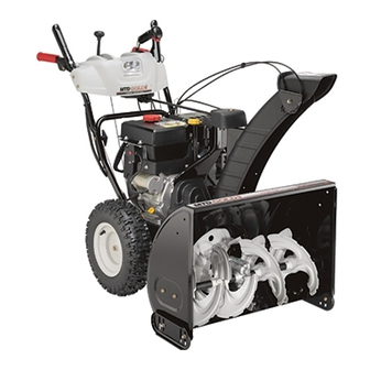
- Page 1 Safe Operation Practices • Set-Up • Operation • Maintenance • Service • Troubleshooting • Warranty OPER roR's Two-Stage Snow Thrower m 500 Series & 600 Series MTD LLC, P.O. BOX 361131 CLEVELAND, OHiO 44136-0019 PrintedIn USA FormNo.769-07070 (May17,2011)
-
Page 2: Serial Number
Choose from the options below: Visit us on the web at www.mtdproducts.com Call a Customer Support Representative at (800) 800-7310 or (330) 220-4683 Write to MTD LLC • RO. Box 361131 • Cleveland, OH • 44136-0019... -
Page 3: Important Safe Operation Practices
ImportantSafeOperation Practices WARNING! This symbol points out important safety instructions which, if not followed, could endanger the personal safety and/or property of yourself and others. Read and follow all instructions in this manual before attempting to operate this machine. Failure to comply with these instructions may result in personal injury. -
Page 4: Safe Handling Of Gasoline
Never run an engine indoors or in a poorly ventilated area. SafeHandlingof Gasoline Engine exhaust contains carbon monoxide, an odorless To avoid personal injury or property damage use extreme care and deadly gas. in handling gasoline. Gasoline is extremely flammable and the Do not operate machine... -
Page 5: Spark Arrestor
According to the Consumer Products Safety Commission Clearing a Clogged Discharge C hute (CPSC) and the U.S. Environmental Protection Agency (EPA), Hand contact with the rotating impeller inside the discharge this product has an Average Useful Life of seven (7) years, chute is the most common cause of injury associated with snow... -
Page 6: Safety Symbols
SafetySymbols This page depicts and describes safety symbols that may appear on this product. Read, understand, and follow all instructions on the machine before attempting to assemble and operate. READTHE OPERATOR'S MANUAL(S) Read,understand, and follow all instructions in the manual(s) before attempting to assemble and operate WARNING-- ROTATING BLADES... -
Page 7: Assembly And Setup
Assembly & Set-Up Contentsof Carton One Snow Thrower Two Replacement Auger Shear Pins One Product Registration Card One Chute Control Rod (if so One Snow Thrower Operator's One Chute Assembly Manual equipped) One Engine Manual There are four chute control styles available that determine your set-up. -
Page 8: Handle Assembly
2-Way& 4-WayAssembly NOTE:Make certain the cables are seated properly in the roller guides. See Fig. 3-2. Remove all loose parts before assembling. HandleAssembly Place the shift lever in the Forward-6 position Observe the lower rear area of the snow thrower to be sure both cables are aligned with roller guides... - Page 9 Place chute onto chute base and ensure chute control ChuteAssembly rod is positioned under the handle panel. Install hex bolt Remove hairpin clip, wing nut and hex screw from chute previously removed but do not secure with wing nut at this control head and clevis pin and bow-tie cotter...
- Page 10 Rotate the joystick to the one o'clock position so that the Push the chute control rod toward the control panel until silver indicator arrow on the pinion gear below the control the hole in the rod lines up with the hole in the chute panel faces upward.
- Page 11 ChuteAssembly OverheadChuteControl Assembly Remove wing nut and hex screw from chute control HandleAssembly assembly and clevis pin and cotter pin from chute support Place the shift lever in the Forward-6 position. bracket. Position the chute assembly (forward-facing) over the chute base. See Fig. 3-12. Observe the lower rear area of the snow thrower to be sure both cables are aligned...
- Page 12 Finish securing chute control assembly to chute support Remove the hairpin clip from the rear of the chute control bracket with wing nut and hex screw removed earlier. assembly. See Fig. 3-14. Insert chute directional control rod into rear of the chute control assembly.
- Page 13 NOTE: Make certain the cables are seated properly in the Close the flange keepers to secure the chute assembly roller guides. See Fig. 3-18. to the chute base. The flange keepers will click into place when properly secure. See Fig. 3-20. Figure 3-18 Figure 3-20 Secure the handle by tightening...
- Page 14 Close the flange keepers to secure the chute assembly U-JointCrankAssembly to the chute base. The flange keepers will click into place Handle when properly secure. See Fig. 3-24. Place the shift lever in the forward-6 position. Observe the lower rear area of the snow thrower to be sure both cables are aligned with roller guides...
-
Page 15: Tire Pressure
Drift Cutters(if soequipped) Set-Up Remove the two screws and lock nuts that secure each ShearPinsStorage (if soequipped) drift cutter, and remove them from the sides of the auger A pair of replacement auger shear pins and bow tie cotter pins housing. - Page 16 Skid Shoes Adjustments The snow thrower skid shoes are adjusted upward at the factory ChuteAssembly for shipping purposes. Adjust them downward, if desired, prior to operating the snow thrower. NOTE: Upper chutes on models with 4-Way Chute Control also controlled by the Chute Directional Control.
- Page 17 Auger Control carefully read and follow all instructions below. WARNING! Prior to operating your snow thrower, Perform all adjustments to verify your snow thrower is operating safely and properly. Check the adjustment of the auger control as follows: When the auger control is released and in the disengaged "up"...
-
Page 18: Controls And Features
Controls a nd Features Shift Lever t _!'J=Way/2=Way Chute Directional Control t __=== Auger Control Headlight t Chute Assembly Drift Cutter Control Tool Overhead Chute Standard Chute Directional Control t Augers U=Joint Chute Directional Control t t if Equipped Figure 4=1 Snow thrower controls and features... -
Page 19: Auger Control
Steering Trigger Controls (If soEquipped) Drift Cutters (If soEquipped) The drift cutters are designed for use in deep snow. Their use STEERING TRIGGER CONTROLS is optional for normal snow conditions. Maneuver the snow thrower so that the cutters penetrate a high standing snow drift to assist snow falling into the augers for throwing. - Page 20 OverheadChute DirectionalControl (Ifso 2-Way Chute Directional Control (IfsoEquipped) Equipped) CHUTE DIRECTIONAL CONTROL CHUTE DIRECTIOHAL CONTROL ADJUSTABLE CHUTETiLT DISCHARGE The overhead chute directional control is located in the center CHUTE ROTATE CHUTE ROTATE LEFT RIGHT the snow thrower between the handle panel and lower handle.
-
Page 21: Operation
Operation Starting and Stopping the Engine Replacing ShearPins Refer to the Engine Operator's Manual packed with your snow The augers are secured to the spiral shaft with shear pins and thrower for instructions on starting and stopping the engine. cotter pins. -
Page 22: Maintenance And Adjustments
Maintenance& Adjustments Maintenance Lubrication GearShaft Engine Refer to the Engine Operator's Manual packed with your snow The gear (hex) shaft should be lubricated at least once a season thrower. or after every twenty-five (25) hours of operation. Tire Pressu re Allow the engine to run until it is out of fuel. - Page 23 Auger Shaft Auger Control At least once a season, remove the shear pins from the auger Refer to the Assembly & Set-up section for instructions shaft. Spray lubricant inside the shaft and around the spacers and adjusting the auger control cable.
-
Page 24: Off-Season Storage
Reinsert the hairpin clip through this hole and the chute Chute BracketAdjustment(Ifso Equipped) control rod. If the spiral at the bottom of the chute directional control is not ChuteAssembly fully engaging with the chute assembly, the chute bracket can be adjusted. - Page 25 Service Carefully pivot the snow thrower up and forward so that it Belt Replacement rests on the auger housing. Auger Belt Remove the frame cover from the underside of the snow thrower by removing the self-tapping screws which secure To remove and replace your snow thrower's auger belt, proceed it.
-
Page 26: Drive Belt
DriveBelt Remove the belt from around the auger pulley, and slip the belt between the support bracket and the auger pulley. To remove and replace your snow thrower's drive belt, proceed See Fig. 7-5. as follows: To prevent spillage, remove all fuel from tank by running engine until it stops. - Page 27 Back out the stop bolt to increase the clearance between Friction WheelRemoval(Multi-Speed 600 Series) the friction wheel disc and friction wheel. See Fig. 7-7. If the snow thrower fails to drive with the drive control engaged, and performing the drive control cable adjustment fails to correct...
- Page 28 Carefully remove the hex nut which secures the hex shaft Follow the previous steps in reverse order to reassemble to the snow thrower frame and lightly tap the shaft's end to components. dislodge the ball bearing from the right side of the frame. Perform the Drive Control test on page 23 in the See Fig.
-
Page 29: Troubleshooting
Troubleshooting Problem Cause Remedy Engine fails to start 1. Choke not in CHOKE position. 1. Move choke to CHOKE position. 2. Spark plug wire disconnected. 2. Connect wire to spark plug. 3. Fuel tank empty or stale fuel. 3. Fill tank with clean, fresh gasoline. 4. -
Page 30: Replacement Parts
Replacement P arts Component Part Number and Description 929-0071At Extension Cord, 110V 954-04050 Auger Drive Belt (22", 24" & 26") 954-04260 Wheel Drive Belt (22", 24" & 26") 954-04195 Auger Drive Belt (28" & 30") 954-04201A Wheel Drive Belt (28" & 30") 684-04159 Friction Wheel Assembly (500 Series) 684-04153... -
Page 31: Attachments & Accessories
Attachments & Accessories The following attachments and accessories are available for your snow thrower. Phone (800) 800-7310 for information regarding compatibility, price and availability (have your full model number and serial number ready). Model Number Description 753-05762A Heated Grips _- 0EM-390-674 Heavy Duty Snow Cab 0EM-390-679... -
Page 32: Limited Warranty
MANUFACTURER'S LiMiTED WARRANTY The limited warranty set forth below is given by MTD LLC with c. Service completed by someone other than an authorized service dealer. respect to new merchandise purchased and used in the United States and/or its territories and possessions, and by MTD Products Limited d.
Need help?
Do you have a question about the 31AH65LG704 and is the answer not in the manual?
Questions and answers