Table of Contents
Advertisement
Quick Links
CONTENTS
1. General .................................................................................................. 1
2. Installation ............................................................................................. 2
3. Connections ........................................................................................... 4
4. HDSL4 System Testing ........................................................................ 5
5. Control Port Operation (HDSL4) ......................................................... 6
6. HDSL4 Deployment Guidelines ........................................................ 16
7. Maintenance ....................................................................................... 20
8. Product Specifications ....................................................................... 20
9. Warranty and Customer Service ........................................................ 20
Appendix A. HDSL4 Loopbacks .......................................................... A-1
220 H4TU-C ........................................................................... 1
H4TU-C Span Powering Diagram ......................................... 5
H4TU-C Bantam Jack Arrangement ...................................... 5
HDSL4 Loopbacks ................................................................. 6
RS-232 (DB-9) Pin Assignments ........................................... 6
HDSL4 Main Menu Screen .................................................... 8
Unit Information Screen ......................................................... 8
Provisioning Screen ................................................................ 9
Span Status Screen ................................................................. 9
Detailed Status Screen ......................................................... 10
Loopbacks and Test Commands Screen ............................. 10
24-Hour H4TU-C Loop Performance Data Screen ............ 11
Screen ................................................................................... 12
Path Related Screen ............................................................. 12
Scratch Pad/Circuit ID and Time/Date Screen ................... 13
T1 Alarm History Screen .................................................... 13
HDSL4 Span History Screen .............................................. 14
Event History Screen ........................................................... 14
Virtual Terminal Control Screen ....................................... 15
HDSL4 Circuit Segments .................................................... 16
Resistance Budget Span Powering Two Repeaters ............ 17
(Example) ............................................................................ 18
TABLES
Compliance Codes .................................................................. 2
Front Panel Indicators ............................................................ 3
Provisioning Options .............................................................. 4
Screen Abbreviations ............................................................. 7
HDSL4 Loop Insertion Loss Values ................................... 16
Single Pair Cable DC Resistance Value ............................. 17
of Repeatered Loop ............................................................. 19
of Repeatered Loop ............................................................. 19
220 H4TU-C Specifications ................................................ 21
Table A-1. HDSL4 Loopback Control Codes ..................................... A-2
Table A-2. Loopback and Control Codes ......................................... A-3,4
61222401L1-5C
220 HDSL4 Transceiver Unit
for the Central Office
Installation and Maintenance Practice
Trademarks: Any brand names and product names included in this document are
trademarks, registered trademarks, or trade names of their respective holders.
CLEI Code: T1L5TWPC_ _
H TUC
1222401L1
TX
E
Q
RX
DSX
TX
M
O
N
RX
R
S
2
3
2
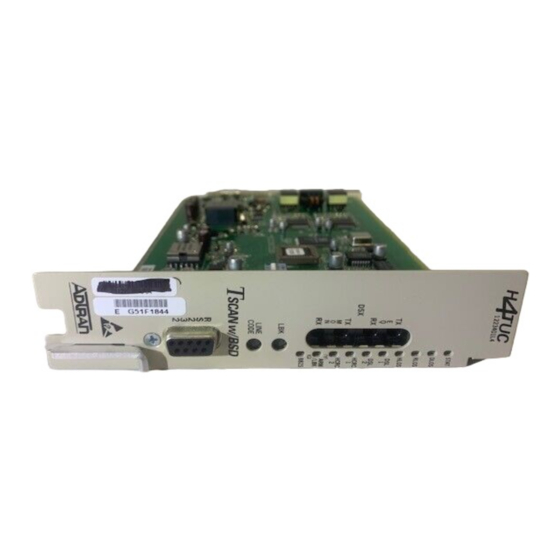
Figure 1. 220 H4TU-C
1. GENERAL
The ADTRAN 220 HDSL4 Transceiver Unit for the
Central Office (H4TU-C) (ADTRAN P/N
1222401L1) is used to deploy an HDSL4 T1 circuit
using 4-wire metallic facilities. See Figure 1. The
unit occupies one slot in a 220 shelf.
The DS1 or DSX-1 input signal is supplied from the
network. The HDSL4 signals are provided to the
local loop. The ADTRAN 220 H4TU-C works in
conjunction with the ADTRAN H4TU-R and up to
two H4Rs to provide a DS1 service on the local loop.
Section 61222401L1-5C
Issue 3, October 2003
DSL
1
DSL
2
DSX
/DS1
ALM
ESF
/SF
B8ZS
/AMI
LBK
1
Advertisement
Table of Contents

Related Manuals for ADTRAN 220 HDSL4


Summary of Contents for ADTRAN 220 HDSL4
-
Page 1: Table Of Contents
Table 1. Compliance Codes ..............2 1. GENERAL Table 2. Front Panel Indicators ............3 The ADTRAN 220 HDSL4 Transceiver Unit for the Table 3. Provisioning Options .............. 4 Table 4. Screen Abbreviations ............. 7 Central Office (H4TU-C) (ADTRAN P/N Table 5. -
Page 2: Installation
The 220 H4TU-C plugs directly into the 220 shelf. contact ADTRAN. For more information, refer to the No installation wiring is required. Warranty and Customer Service section. There are no configuration switches for the H4TU-C. -
Page 3: Table 2. Front Panel Indicators
Powering Options The H4TU-C is default enabled for span powering mode. The H4TU-C will power one, two, or three elements and can be set to span power Disabled when the H4TU-R is locally powered and there are no H4Rs on the circuit. Table 2. -
Page 4: Connections
Provisioning 3. CONNECTIONS Through management access via the front panel The 220 H4TU-C occupies one card slot in a 220 RS-232 port, the provisioning settings can be viewed shelf. Power and alarm signals are provided to the and manipulated. Table 3 lists the available card through the backplane of the shelf. -
Page 5: Hdsl4 System Testing
The H4TU-C responds to two different loopback 4. HDSL4 SYSTEM TESTING activation processes. The ADTRAN HDSL4 system provides the ability to monitor the status and performance of the DSX-1 First, loopbacks may be activated using the craft signals, DS1 signals, and HDSL4 loop signals. -
Page 6: Control Port Operation (Hdsl4)
DSX-1 signal passes into the HDSL4 modulators. connection to a controlling terminal. The pinout of Figure 4 depicts all of the loopback locations possible with ADTRAN HDSL4 equipment. the DB-9 is illustrated in Figure 5. H4TU-C Network-Side Loopback LOCAL... -
Page 7: Table 4. Screen Abbreviations
The screens illustrated in Figure 6 through Figure 21 communication between the computer and the HDSL4 are for an HDSL4 circuit deployed with ADTRAN’s unit may be periodically disrupted if power saving HDSL4 technology. The circuit includes an H4TU-C, programs are being used on the personal computer. -
Page 8: Figure 6. Hdsl4 Main Menu Screen
From the ADTRAN HDSL4 Main Menu (Figure 6), 7. Terminal Modes the following screens can be accessed. 8. Alarm History 9. Event History 1. HDSL4 Unit Information 10. System PM/Screen Report 2. Provisioning 11. Virtual Terminal Control 3. Span Status 4. -
Page 9: Figure 8. Provisioning Screen
The Provisioning screen (Figure 8) displays current The options shown in Table 3 are available with the provisioning settings for the HDSL4 circuit. Options H4TU-R (P/N1222426L1). Some settings may differ that can be changed from this screen are labeled with when using different H4TU-Rs. -
Page 10: Figure 10. Detailed Status Screen
The Detailed Status screen from the Span Status menu Each HDSL4 circuit component can be looped toward (Figure 10) displays the HDSL4 status for each the network or customer from this screen. Unit self receiver point. tests can also be initiated from this screen. The Loopbacks and Test Commands screen (Figure 11) provides the user with the ability to invoke or terminate all available HDSL4 loopbacks. -
Page 11: Figure 12. 15-Minute H4Tu-C Dsx-1 Performance Data Screen
The Performance History screens (Figure 12 and 24-hour period. At each 24-hour interval, the Figure 13) are used to select and display the historical performance data is transferred into the 24-hour HDSL4 and T1 performance data in several different performance data registers. This unit stores up to 31 registers. -
Page 12: Figure 14. Performance Data Definitions - Hdsl4 Loop Related Screen
Abbreviations used in the Performance History screens are defined in Data Definitions screens. (See Figure 14 and Figure 15.) Circuit ID: 04/17/02 05:06:23 Performance Data Definitions H4TUC, H4TUR, and H4R LOOP Related: HDSL4 Framing ES-L Errored Seconds CRC>=1 or LOSW>=1 SES-L Severely Errored Seconds CRC>=50 or LOSW>=1... -
Page 13: Figure 16. Scratch Pad/Circuit Id And Time/Date Screen
Figure 16 illustrates the Scratch Pad, Circuit ID, Time The T1 Alarm History screen and HDSL4 Span and Date Screen. The Scratch Pad field has been History Screen, Figure 17 and Figure 18 respectively, designed for use by technicians. The field can be any provide the user with a detailed alarm history and alpha-numeric string up to 50 characters in length. -
Page 14: Figure 18. Hdsl4 Span History Screen
The Event History screen (Figure 19) provides a log history of HDSL4 circuit events. CIRCUIT ID:ABC123 01/25/02 11:52:00 Press ESC to return to previous menu HDSL4 Span History LOCATION ALARM FIRST LAST CURRENT COUNT --------------------------------------------------------------------------------- SPAN C-H1 H4TU-C MRGN MRGN H4R1 NET MRGN MRGN... -
Page 15: Figure 20. System Pm/Screen Report Screen
The System PM/Screen Report option from the Main The Virtual Terminal Control screen (Figure 21) is Menu offers four types of reports on performance used to log onto the H4TU unit at the opposite end of monitoring. Selecting a report type will then display the circuit. -
Page 16: Hdsl4 Deployment Guidelines
DC resistance. DSL Assistant must be used to engineer HDSL4 circuits with two repeaters. The segment resistance (W segment) is determined using the equation provided below. The ADTRAN HDSL4 system provides DS1-based Ω * Ω * Ω * Ω... -
Page 17: Figure 23. Resistance Budget Span Powering Two Repeaters
Table 6. Single Pair Cable DC Resistance Value ) . t F º F º F º F º t a l F º F º t a l F º F º 2. Find the first segment resistance on the vertical 5. -
Page 18: Figure 24. Resistance Budget Span Powering Two Repeaters (Example)
2. Find the 600 ohm first segment resistance point An example problem is illustrated in Figure 24. For this example, begin with three known measurements: on the vertical axis. 600 ohm first segment resistance, 700 ohm second 3. Find the 700 ohm second segment resistance segment resistance, and 900 ohm third segment point on the horizontal axis. -
Page 19: Table 7. Qualification Worksheet For Single Span And First Segment
Simplified Loop Qualification Procedure Second Segment of Repeatered Loop The field technician should be provided with the For each of the three measured insertion loss values, expected insertion loss at four frequencies, based on compute the difference between the maximum loss the engineering loop design. -
Page 20: Maintenance
ADTRAN does not recommend that repairs be ADTRAN Technical Support performed in the field. Repair services may be Pre-Sales Applications/Post-Sales Technical Assistance: obtained by returning the defective unit to ADTRAN. 800-726-8663 For more information refer to Warranty and Customer Service section. -
Page 21: Table 9. 220 H4Tu-C Specifications
Table 9. 220 H4TU-C Specifications i t a l a i i l e s r i t s r , ) t n i l i t c i t i s l i < , . t l a t <... - Page 22 This page is intentionally blank. 61222401L1-5C...
-
Page 23: Appendix Ahdsl4 Loopbacks
Appendix A HDSL4 Loopbacks HDSL4 MAINTENANCE MODES Loopback Control Codes A summary of control sequences is given in This appendix describes operation of the HDSL4 Table A-1 and Table A-2. system with regard to detection of in-band and ESF facility data link loopback codes. NOTE Upon deactivation of a loopback, the HDSL4 system In all control code sequences presented, the... -
Page 24: Table A-1. Hdsl4 Loopback Control Codes
Table A-1. HDSL4 Loopback Control Codes 2, 3 Type Source Code Name Abbreviated (N) ....3in7 (1110000) Loopback data from network toward network in the HTU-R. (N) ....4in7 (1111000) Loopback data from network toward network in the HTU-C. (N) ....2in6 (110000) Loopback data from network toward network in first HRE. -
Page 25: Table A-2. Loopback And Control Codes
Table A-2. Loopback and Control Codes − e t t s t i l l i e t t l l i e t t s t i l l i i l i l l i e t t i t c i l a . - Page 26 Table A-2. Loopback and Control Codes (continued) s t i i r r e t t l l i s t i l l i s t i l l i t t e r i f i t a l l i .
Need help?
Do you have a question about the 220 HDSL4 and is the answer not in the manual?
Questions and answers