ADTRAN 3192 HDSL4 Installation And Maintenance Practice
Remote, span powered transceiver
Hide thumbs
Also See for 3192 HDSL4:
Table of Contents
Advertisement
Quick Links
Advertisement
Table of Contents
Troubleshooting

Related Manuals for ADTRAN 3192 HDSL4


Summary of Contents for ADTRAN 3192 HDSL4
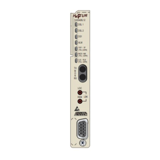
- Page 1 ® 3192 HDSL4 Transceiver, Remote, Span Powered Installation and Maintenance Practice 1223426L12 DSL 1 DSL 2 ESF / SF (YEL) (GRN) B8ZS / AMI (YEL) (GRN) LLB / RLB (YEL) (GRN) REM LBK 1223426L12 3192 HDSL4 H4TU-R, Span Powered CLEI: T1L8CEACAA...
- Page 2 In no event will ADTRAN be liable for any special, incidental, or consequential damages or for commercial losses even if ADTRAN has been advised thereof as a result of issue of this publication.
-
Page 3: Revision History
3192 HDSL4 Transceiver, Remote, Span Powered Installation and Maintenance Practice Revision History The history of this document is as follows: Revision Release Date Description September 2004 This is the initial issue of this practice. Conventions The following typographical conventions are used in this document: indicates keyboard keys (i.e.,... - Page 4 3192 HDSL4 Transceiver, Remote, Span Powered Installation and Maintenance Practice Training ADTRAN offers training courses on our products. These courses include overviews on product features and functions while covering applications of ADTRAN’s product lines. ADTRAN provides a variety of training options, including customized training and course taught at our facilities or at customer sites.
-
Page 5: Table Of Contents
ADTRAN Technical Support ........ - Page 6 ADTRAN HDSL4 3192 H4TU-R, Span Powered ........
- Page 7 ADTRAN Unit Compatibility ........
- Page 8 3192 H4TU-R, Span Powered Installation and Maintenance Practice Contents viii 61223426L12-5A...
-
Page 9: Product Description
PRODUCT DESCRIPTION ® The ADTRAN 4-wire 3192 HDSL4 Transceiver Unit for the Remote end (H4TU-R), P/N 1223426L12, is a network terminating unit used to deploy an HDSL4 T1 circuit using 4-wire metallic facilities. See Figure 1. This H4TU-R is designed to be installed in a 3192 chassis. -
Page 10: Compliance
3192 H4TU-R, Span Powered Installation and Maintenance Practice This version of the H4TU-R works with multiple list versions of the HDSL4 Transceiver Unit for the Central Office (H4TU-C) and repeater (H4R) as listed in Table Table 1. ADTRAN Unit Compatibility Unit Number Description 122x401L1 or L2... -
Page 11: Installation Procedure
3192 H4TU-R, Span Powered Installation and Maintenance Practice Front Panel Operation CAUTION Electronic modules can be damaged by ESD. When handling modules, wear an antistatic discharge wrist strap to prevent damage to electronic components. Place modules in antistatic packing material when transporting or storing. When working on modules, always place them on an approved antistatic mat that is electrically grounded. -
Page 12: Front Panel Led Indicators
Front Panel Operation 3192 H4TU-R, Span Powered Installation and Maintenance Practice Front Panel LED Indicators There are seven front panel mounted status LED indicators. Each indicator is described in Table Table 3. Front Panel Indicators Front Indication Description Panel DSL Loop 1 sync, no errors currently detected, and signal margin ≥ 3 dB DSL 1 Green No DSL Loop 1 sync, errors being detected, or signal margin <... -
Page 13: Table 4. Provisioning Options
3192 H4TU-R, Span Powered Installation and Maintenance Practice Front Panel Operation Table 4. Provisioning Options Provisioning Option Option Settings Default Setting 1. DSX-1 Line Build Out 0–133 ft. 0 to 133 ft. 133–266 ft. 266–399 ft. 399–533 ft. 533–655 ft. 2. -
Page 14: Connections
Connections 3192 H4TU-R, Span Powered Installation and Maintenance Practice CONNECTIONS All connections of the 3192 H4TU-R, Span Powered are made through card edge connectors. Figure 2 shows the card edge pin assignments for the 3192 H4TU-R, Span Powered circuit pack. DS1 Rx (Ring) Input DS1 Tx (Ring) Output 48 VDC Return... -
Page 15: Hdsl4 System Testing
3192 H4TU-R, Span Powered Installation and Maintenance Practice HDSL4 System Testing HDSL4 SYSTEM TESTING The 3192 H4TU-R, Span Powered provides diagnostic, loopback, and signal monitoring capabilities. The front panel LEDs provide diagnostics for HDSL4 loops, DS1 signals, alarms, provisioning, and loopbacks. Refer to the Installation section for details. -
Page 16: H4Tu-R Network Loopbacks
HDSL4 System Testing 3192 H4TU-R, Span Powered Installation and Maintenance Practice H4TU-R Network Loopbacks The loopback position is a logic loopback located within the H4TU-R internal HDSL4 transceiver. See Figure H4TU-C Network-Side Loopback LOCAL DSX-1 LOOP H4TU-C H4TU-R H4TU-R Network-Side Loopback and/or H4TU-R NIU Loopback LOCAL DSX-1... -
Page 17: Customer Loopbacks
3192 H4TU-R, Span Powered Installation and Maintenance Practice HDSL4 System Testing The H4TU-R responds to multiple loopback activation processes. • First, manual loopback on the H4TU-R and/or the H4TU-C unit can be controlled from the front panel. Refer Front Panel Operation on page 3 of this practice for more detail. -
Page 18: Control Port Operation
Operation The screens illustrated in this section apply to an HDSL4 circuit deployed with the ADTRAN HDSL4 technology. The circuit includes an H4TU-C, up to two H4Rs and an H4TU-R. Other configurations are possible (such as use of another vendor's equipment) and their displays will vary slightly from those shown in this section. -
Page 19: Figure 6. Hdsl4 Main Menu
Figure 7) provides detailed product information on each component in the Unit Information HDSL4 circuit. This screen also displays contact information for ADTRAN Technical Support, Internet site, and address. Circuit ID: 06/01/04 09:29:45 Press ESC to return to previous menu... -
Page 20: Figure 8. Provisioning Menu
Control Port Operation 3192 H4TU-R, Span Powered Installation and Maintenance Practice Provisioning menu (Figure 8) displays current provisioning settings for the HDSL4 circuit. Options that can be changed from this screen are labeled with a number (for example, “1” for DSX-1 Line Build Out). To change a particular option setting, select the appropriate option and press , and a new menu will appear with a list of NTER... -
Page 21: Figure 9. Span Status Screen
3192 H4TU-R, Span Powered Installation and Maintenance Practice Control Port Operation Span Status Screen (Figure 9) provides quick access to status information for each HDSL4 receiver in the circuit. Circuit ID: 06/01/04 09:29:45 Press ESC to return to previous menu Span Status Screen ______ ______... -
Page 22: Figure 11. Loopbacks And Test Commands Menu
Control Port Operation 3192 H4TU-R, Span Powered Installation and Maintenance Practice Loopbacks and Test Commands menu (Figure 11) provides the ability to invoke or terminate all available HDSL4 loopbacks. Each HDSL4 circuit component can be looped toward the network or customer from this screen. Unit self-tests can also be initiated from this screen. -
Page 23: Figure 12. 15-Minute Performance Data Screen
3192 H4TU-R, Span Powered Installation and Maintenance Practice Control Port Operation Circuit ID: 06/01/04 09:29:45 Press ESC to return to previous menu Menu 15 Minute H4TUC DSX-1 Performance Data Definitions ES-L SES-L LOSS-L CV-L Reset Data 00000 15 Min Data 14:15 000 00000 60 Min Data... -
Page 24: Figure 14. Performance Data Definitions
Control Port Operation 3192 H4TU-R, Span Powered Installation and Maintenance Practice Circuit ID: 06/01/04 09:29:45 Performance Data Definitions H4TUC, H4TUR, and H4R LOOP Related: HDSL4 Framing ES-L Errored Seconds CRC>=1 or LOSW>=1 SES-L Severely Errored Seconds CRC>=50 or LOSW>=1 UAS-L Unavailable Seconds >10 cont. -
Page 25: Figure 16. Scratch Pad, Circuit Id, And Time/Date Screen
3192 H4TU-R, Span Powered Installation and Maintenance Practice Control Port Operation Scratch Pad, Circuit ID, and Time/Date screen (Figure 16) provides a Scratch Pad for user-defined information and can be any alphanumeric string up to 50 characters in length. The Circuit ID can be any alphanumeric string up to 25 characters in length. -
Page 26: Figure 18. Hdsl4 Span History Screen
Control Port Operation 3192 H4TU-R, Span Powered Installation and Maintenance Practice HDSL4 Span History menu (Figure 18) provides a detailed alarm history and events log for the HDSL4 circuit. This screen includes a time, date, first and last occurrence, and count for each type of T1 alarm. Circuit ID: 06/01/04 09:29:45 Press ESC to return to previous menu... -
Page 27: Figure 20. System Pm/Screen Report Option
(Figure 21) initializes data from performance monitoring and alarm histories. Selecting this option from the Main Menu requires a confirmation to continue (Y/N). Circuit ID: 06/01/04 09:29:45 Adtran HDSL4 Main Menu HDSL4 Unit Information Provisioning Span Status Loopbacks and Test... -
Page 28: Figure 22. Troubleshooting Screen
Press ESC to return to previous menu Troubleshooting For HELP based on detected problems, select Troubleshooting Guidance from the list below. If further assistance is needed, contact ADTRAN Tech Support. Hours: Normal 7am - 7pm CST 1. Troubleshooting Guidance Emergency 7 days x 24 hours 2. -
Page 29: Figure 24. General Information Screen
3192 H4TU-R, Span Powered Installation and Maintenance Practice Control Port Operation General Information screen (Figure 24), from the Troubleshooting screen, provides a summary of the deploy- ment guidelines necessary to provision this HDSL4 circuit. Circuit ID: 06/01/04 09:29:45 Press ESC to return to previous menu HDSL4 Loop Guidelines for optimum operation ------------------------------------------- Non-loaded cable pair... -
Page 30: Chronic Circuit Problems Screen
Control Port Operation 3192 H4TU-R, Span Powered Installation and Maintenance Practice Chronic Circuit Problems Screen Selecting the Chronic Circuit Problems screen (Figure 25) from the Troubleshooting screen gives the technician some general information about circuits with bad splices. Splices that are varying in impedance will cause the HDSL data pump to see a reduced and/or fluctuating signal quality (margin). -
Page 31: Figure 26. View Splice Results Screen
3192 H4TU-R, Span Powered Installation and Maintenance Practice Control Port Operation View Splice Results Selecting the View Splice Results screen (Figure 26) will report one of three things for each transceiver in the Splice Detection Results column: • NTF - No Trouble Found •... -
Page 32: Figure 27. Histogram Screen
Control Port Operation 3192 H4TU-R, Span Powered Installation and Maintenance Practice Splice Histogram The Splice Histogram Screen (Figure 27) displays the counters that the splice detector uses to make its result decision. The definitions of abbreviations shown on this screen are as follows: The first column, labeled Splice (feet) , represents the distance from the H4TU-C that the anomaly detector is evalu-... -
Page 33: Figure 28. Virtual Terminal Session Screen
3192 H4TU-R, Span Powered Installation and Maintenance Practice Control Port Operation Virtual Terminal Session screen (Figure 28) allows control of the far-end HDSL4 unit provisioning from the H4TU-R. Select this option to begin a user-initiated session with the far-end unit. When the remote session is completed, Press to terminate the session. -
Page 34: Hdsl4 Deployment Guidelines
Figure Figure 29. HDSL4 Circuit Segments The ADTRAN HDSL4 system provides DS1-based services over loops designed to comply with the guidelines given below. These guidelines apply to the following circuit configurations: • a single segment or an HDSL4 circuit with no H4Rs, •... -
Page 35: Table 6. Range Limits: 26 Gauge / 70°F / Pic
3192 H4TU-R, Span Powered Installation and Maintenance Practice HDSL4 Deployment Guidelines Table 6. Range Limits: 26 Gauge / 70°F / PIC 26 Gauge Recommended Maximum 10,470 ft. segment 9,865 ft. segment 9,865 ft. (see note) segment Table 7. Range Limits: 24 Gauge / 70°F / PIC 24 Gauge Recommended Maximum 14,770 ft. -
Page 36: Figure 30. Resistance Budget Span Powering Two Repeaters
HDSL4 Deployment Guidelines 3192 H4TU-R, Span Powered Installation and Maintenance Practice Once the resistance of each segment is confirmed, refer to Figure 30 to decide if the H4TU-C is capable of span powering two H4Rs and one H4TU-R. Alternatively, the DSL Assistant program will automatically calculate this and report any violations. -
Page 37: Figure 31. Resistance Budget Span Powering (Example)
3192 H4TU-R, Span Powered Installation and Maintenance Practice HDSL4 Deployment Guidelines An example problem is illustrated in Figure 31. For this example, begin with three known measurements: 600 ohms first segment resistance, 700 ohms second segment resistance, and 900 ohms third segment resistance. -
Page 38: Maintenance
Troubleshooting Guide in Table ADTRAN does not recommend that repairs be attempted in the field. Repair services may be obtained by returning the defective unit to ADTRAN. Refer to the Warranty and Customer Service section for further information. -
Page 39: Table 10. Hdsl4 3192 H4Tu-R, Span Powered Specifications
399–533 ft. ABAM 533–655 ft. ABAM DSX-1 Line Code B8ZS (default), AMI Power Tested with the ADTRAN H4TU-C (P/N 1223401L2) and H4R (P/N 1223445L1) H4TU-R Power Dissipation 3.8 watts Span Power 190 VDC (from H4TU-C) Class A2 Compliant, GFI Current Limited at <... - Page 40 Specifications 3192 H4TU-R, Span Powered Installation and Maintenance Practice Table 10. HDSL4 3192 H4TU-R, Span Powered Specifications Environment Operating Temperature (Standard) –40°C to + 70°C Storage Temperature –40°C to + 85°C Compliance UL 60950; GR-1089-CORE; GR-63-CORE; ANSI T1.418-2001, Issue 2; ANSI T1.102 (DS1 Interface) Part Number 3192 H4TU-R, Span Powered 1223426L12...
-
Page 41: 10. Warranty And Customer Service
Warranty and Customer Service 10. WARRANTY AND CUSTOMER SERVICE ADTRAN will replace or repair this product within the warranty period if it does not meet its published specifica- tions or fails while in service. Warranty information can be found at www.adtran.com/warranty. - Page 42 Warranty and Customer Service 3192 H4TU-R, Span Powered Installation and Maintenance Practice This page is intentionally blank. 61223426L12-5A...
-
Page 43: Hdsl4 Maintenance Modes
Appendix A HDSL4 Loopbacks HDSL4 MAINTENANCE MODES This appendix describes operation of the HDSL4 system with regard to detection of in-band and ESF Facility Data Link loopback codes. Upon deactivation of a loopback, the HDSL4 system will synchronize automatically. Loopback Process Description In general, the loopback process for the HDSL4 system elements is modeled on the corresponding DS1 system process. -
Page 44: Table A-1. Hdsl4 Loopback Control Codes
HDSL2 for Verizon Installation and Maintenance Practice Table A-1. HDSL4 Loopback Control Codes Type Name Source Code Abbrevi- 3in7 (1110000) Loopback data from network toward network in the H4TU-R ated 4in7 (1111000) Loopback data from network toward network in the H4TU-C 2in6 (110000) Loopback data from network toward network in first H4R 3in6 (111000) -
Page 45: Table A-2. Loopback Control Codes
HDSL2 for Verizon Installation and Maintenance Practice Table A-2. Loopback Control Codes Function Code (Hex / Binary) Response ARM (in-band) 11000 (binary) also known If the pattern is sent from the network, the units will arm, as 2-in-5 pattern and the H4TU-R will loop up if NIU Loopback is enabled. ARM (ESF Data Link) FF48 or If the pattern is sent from the network, the units will arm,... - Page 46 HDSL2 for Verizon Installation and Maintenance Practice Table A-2. Loopback Control Codes (Continued) Function Code (Hex / Binary) Response 6767 or If the units are armed and 6767 is sent from the network, Span Power Disable 0110 0111 0110 0111 the H4TU-C will disable span power.
-
Page 47: Hdsl4 Features
• Fast Retrain • Splice Detection Feature The Runtime TScan splice detection feature is an ADTRAN proprietary non-intrusive algorithm for detection of anomalies (bad splices) in the copper pair. Data transmission transceivers (especially echo-cancelled technologies) are subject to performance degra- dations and errors in the presence of bad splices. -
Page 48: Splice Detection Algorithm
Appendix B HDSL2 for Verizon Installation and Maintenance Practice Splice Detection Algorithm The splice detection algorithm is designed to detect bad splices in training mode and data mode. The train- ing mode detection is important if the splice is bad enough to prevent synchronization. In data mode, the detector will run periodically after synchronization is achieved. -
Page 49: Splice Detection Screens
HDSL2 for Verizon Installation and Maintenance Practice Appendix B Splice Detection Screens Chronic Circuit Screen The Chronic Circuit screen (Figure B-1) displays general information about circuits with bad splices. Circuit ID: Chronic Circuit 01/01/00 03:34:00 Press ESC to return to previous menu Chronic Circuit Problems Field experience has shown that many chronic circuit failures are due to bad splices. -
Page 50: View Splice Results Screen
Appendix B HDSL2 for Verizon Installation and Maintenance Practice View Splice Results Screen Selecting the View Splice Results option from the menu displays this screen (Figure B-2). Results will be reported in the Splice Detection Results column for each transceiver: •... -
Page 51: View Splice Histogram Screen
HDSL2 for Verizon Installation and Maintenance Practice Appendix B View Splice Histogram Screen The Splice Histogram Screen (Figure B-3) displays the counters that the splice detector uses to make its result decision. The definitions of abbreviations shown on this screen are as follows: •... -
Page 52: Event History Screen
Appendix B HDSL2 for Verizon Installation and Maintenance Practice Event History Screen The Event History screen (Figure B-4) shows the messages reported in the event log due to the splice detector. Any reset of the detector is shown as well as the first detect seen since the last reset. Circuit ID: Chronic Circuit 04/14/04 03:31:36... -
Page 53: Fast Retrain Feature
FAST RETRAIN FEATURE Fast Retrain is an ADTRAN proprietary feature whose intent is to minimize downtime when an intermit- tent non power-related impairment (bad splice, noise burst, etc.) affects the HDSL loop and cannot be bridged. - Page 54 Appendix B HDSL2 for Verizon Installation and Maintenance Practice This page is intentionally blank. 61223426L12-5A...
Need help?
Do you have a question about the 3192 HDSL4 and is the answer not in the manual?
Questions and answers