
Related Manuals for MSI Micro ATX


Summary of Contents for MSI Micro ATX
- Page 1 MICRO-STAR INTERNATIONAL MS-6394 (v1.X) Micro ATX Mainboard Version 1.0 G52-MA00315...
- Page 2 Manual Rev: 1.0 Release Date: Nov. 2001 FCC-B Radio Frequency Interference Statement This equipment has been tested and found to comply with the limits for a class B digital device, pursuant to part 15 of the FCC rules. These limits are designed to provide reasonable protection against harmful interference when the equip- ment is operated in a commercial environment.
- Page 3 Edition Nov. 2001 Copyright Notice The material in this document is the intellectual property of MICRO-STAR INTERNATIONAL. We take every care in the preparation of this document, but no guarantee is given as to the correctness of its contents. Our products are under continual improvement and we reserve the right to make changes without notice.
- Page 4 Safety Instructions Always read the safety instructions carefully. Keep this User’s Manual for future reference. Keep this equipment away from humidity. Lay this equipment on a reliable flat surface before setting it up. The openings on the enclosure are for air convection hence protects the equipment from overheating.
-
Page 5: Table Of Contents
Mainboard Specifications ............1-2 Mainboard Layout ..............1-5 Quick Components Guide ............1-6 Key Features ................1-7 MSI Special Features ..............1-8 D-LED™ ................1-8 T.O.P Tech™ ..............1-10 Chapter 2. Hardware Setup ............2-1 Central Processing Unit: CPU ........... 2-2 CPU Installation Procedures .......... - Page 6 Wake On Ring Connector: JMDM1 ........2-13 Hard Disk Connectors: IDE1 & IDE2 ......... 2-14 IDE RAID Connectors: IDE3 & IDE4 ........2-15 Case Connector: JFP1 ............2-16 Fan Power Connectors: CPUFAN1/SFAN1/Power Fan ..2-17 I2C Clock/Data Connector: HD THERM1 ......2-18 Serial Connector: JDIP1 ............
- Page 7 Power Management Setup ............3-20 PNP/PCI Configurations ............3-23 PC Health Status ..............3-25 Load Fail-Safe/Optimized Defaults .......... 3-26 Set Supervisor/User Password ..........3-27 Glossary ..................G-1...
-
Page 8: Chapter 1. Introduction
Introduction Chapter 1. Introduction The MS-6394 V1.X Micro ATX mainboard is a high-performance compu- ter mainboard based on ServerWorks ® LC-T North Bridge & ServerWorks ® CSB5 South Bridge chipsets. The MS-6394 is designed for Intel Pentium ® ® (FC-PGA) processor for cost-effective business/personal desktop and entry- level server markets. -
Page 9: Mainboard Specifications
Chapter 1 Mainboard Specifications Support Single Socket370 for Intel Coppermine / Tualatin processors. ® Support up to 1.26GHz at 133MHz FSB Chipset ServerWorks ® LC-T chipset - 100/133MHz Host Bus Interface - Main memory interface with optimized support for PC100/PC133 SDRAM - 32-bit, 33MHz Primary PCI Bus Interface - 64-bit, 33/66MHz Secondary PCI Bus Interface - Extensive Data Buffering between all interfaces for high throughput and... - Page 10 Introduction On-Board IDE An IDE controller on the CSB5 chipset provides IDE HDD/CD-ROM with PIO, Bus Master and Ultra DMA33/66/100 operation modes. Can connect up to four fast IDE drives ATA RAID 0.1 supported by Promise PDC20265R IDE RAID controller. On-Board Peripherals On-Board Peripherals include: - 1 floppy port supports 2 FDD with 360K, 720K, 1.2M,...
- Page 11 Chapter 1 DMI support RTC (Real -Time Clock) wakeup External modem remote ring-on when system is in Soft-Off state BIOS rescure hot keys for rescuing BIOS chip from flash failure Hardware BIOS virus protection 4 MB flash ROM PC Health Monitoring Two onboard voltage monitors for CPU core/s, 3.3V, -12V, -5V, 5VSB, VTT status monitor CPU/chassis temperature monitoring...
-
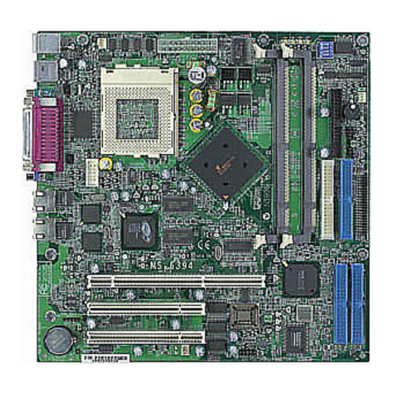
Page 12: Mainboard Layout
Bottom: COM A ServerWorks LC-T COM 2 Display Memory Intel JSPRD1 82550 Rage XL Display Intel Memory 82550 Clock Generator ServerWorks CS B5 64-bit PCI Slot 32-bit PCI Slot 1 BIOS JMDM1 JBAT1 JUSB1 SFAN1 MS-6394 V1.X Micro ATX Mainboard... -
Page 13: Quick Components Guide
Chapter 1 Quick Components Guide Component Function Reference CPU Ratio Setting Switch See p. 2-4 JWR1 ATX 20-Pin Power Connector See p. 2-8 JKBMS1 Mouse & Keyboard Connectors See p. 2-9 USB Connectors Connecting to USB devices See p. 2-10 RJ-45 LAN Jacks See p. -
Page 14: Key Features
Introduction Key Features Micro-ATX form factor Power-up mode control upon recovery from AC power loss D-LED (Diagnostic LED) Onboard overheat buzzer Modem (External/Internal) Ring Wake up Function... -
Page 15: Msi Special Features
Chapter 1 MSI Special Features D-LED™ The D-LED™ uses graphic signal display to help users understand their system. Four LEDs embedded in the mainboard provide up to 16 combi- nations of signals to debug the system. The 4 LEDs can debug all problems that fail the system, such as VGA, RAM or other failures. - Page 16 Introduction Processor Initialization - This will show information regarding the processor (like brand name, system bus, etc…) Testing RTC (Real Time Clock) Initializing Video Interface - This will start detecting CPU clock, checking type of video onboard. Then, detect and initialize the video adapter. BIOS Sign On - This will start showing information about logo, processor brand name, etc….
-
Page 17: T.o.p Tech
Chapter 1 T.O.P Tech™ The T.O.P Tech is an extended sensing device that can 100% accu- rately detect the CPU’s temperature. You can find out the temperature on BIOS setup menu. The PC Alert also provides the information. CPU temperature on Setup menu 1-10... -
Page 18: Chapter 2. Hardware Setup
Hardware Setup C h a p t e r Hardware Setup This chapter provides you with the information about hardware setup procedures. While doing the installation, be careful in holding the components and follow the installation procedures. For some components, if you install in the wrong orientation, the components will not work properly. -
Page 19: Central Processing Unit: Cpu
Chapter 2 Central Processing Unit: CPU ® ® ® The mainboard operates with Intel Pentium III, Intel Coppermine Tualatin processors. The mainboard uses a CPU socket called Socket 370 for easy CPU installation. The CPU should always have a Heat Sink and a cooling fan attached to prevent overheating. -
Page 20: Cpu Core Speed Derivation Procedure
Hardware Setup CPU Core Speed Derivation Procedure CPU Clock 100MHz Core/Bus ratio then CPU core speed Host Clock x Core/Bus ratio 100MHz x 8.5 850MHz While replacing the CPU, always turn off the ATX power supply or unplug the power cable of the ATX WARNING! power supply from grounded outlet first to ensure the safety of CPU. -
Page 21: Cpu Ratio Setting Switch: Sw1
Chapter 2 CPU Ratio Setting Switch: SW1 The SW1 switch is used to set the CPU core ratio. See the table below for details of ratio setting. CPU Ratio X5.5 / X9.5 X6 / X10 X6.5 / X10.5 X7.5 X8.5 / X4.5... -
Page 22: Memory Installation
Hardware Setup Memory Installation The mainboard provides 2 sockets for 168-pin, 3.3V Register SDRAM DIMM only with 4 memory banks. To operate properly, at least one DIMM module must be installed. The mainboard supports the memory size up to 2GB. Introduction to SDR SDRAM Synchronous DRAM is a type of dynamic RAM memory chip that has been widely used starting in the latter part of the 1990s. - Page 23 Chapter 2 MA mapping for Row and Column Address for SDRAM Size/ BA BA 12 11 10 9 SDRAM (0) (1) Size Depth in MB/ Index Value 10 9 32/0 4-bank 12X8 13* 12* 11 24 23 22 21 20 19 18 17 16 15 11 10 9 16/1...
-
Page 24: Sdram Module Combination
Hardware Setup SDRAM Module Combination You can install memory modules in any combination as follows: Slot Memory Module Total Memory Slot 1 64MB, 128MB, 64MB~1GB (Bank 0 & Bank 1) 256MB, 512MB, 1GB Slot 2 64MB, 128MB, 64MB~1GB (Bank 2 & Bank 3) 256MB, 512MB, 1GB 64MB~2GB Total System Memory... -
Page 25: Power Supply
Chapter 2 Power Supply The mainboard supports ATX power supply for the power system. Before inserting the power supply connector, always make sure that all components are installed properly to ensure that no damage will be caused. ATX 20-Pin Power Connector: JWR1 This connector allows you to connect to an ATX power supply. -
Page 26: Back Panel
Hardware Setup Back Panel The Back Panel provides the following connectors: Mouse Paralle Port COM A LAN 1 LAN 2 Keyboard Mouse Connector ® The mainboard provides a standard PS/2 mouse mini DIN connector for at- ® ® taching a PS/2 mouse. -
Page 27: Usb Connectors
Chapter 2 USB Connectors The mainboard provides a UHCI (Universal Host Controller Interface) Univer- sal Serial Bus root for attaching USB devices such as keyboard, mouse or other USB-compatible devices. You can plug the USB device directly into ths connector. USB Port Description SIGNAL DESCRIPTION... -
Page 28: Parallel Port Connector
Hardware Setup Parallel Port Connector The mainboard provides a 25-pin female centronic connector as LPT. A paral- lel port is a standard printer port that supports Enhanced Parallel Port (EPP) and Extended Capabilities Parallel Port (ECP) mode. Pin Definition SIGNAL DESCRIPTION STROBE Strobe... -
Page 29: Serial Port Connector: Com A & Com 2
Chapter 2 Serial Port Connector: COM A & COM 2 The mainboard has two 9-pin serial port connectors, one (COM A) in the back panel and one (COM 2) on-board. You can attach a serial mouse or other serial devices to them. COM A Pin Definition 1 2 3 4 5... -
Page 30: Connectors
Hardware Setup Connectors The mainboard provides connectors to connect to FDD, IDE HDD, case, modem, LAN, USB Ports, IR module and CPU/Power supply/System FAN. Floppy Disk Drive Connector: FDD1 The mainboard provides a standard floppy disk drive connector that supports 360K, 720K, 1.2M, 1.44M and 2.88M floppy disk types. -
Page 31: Hard Disk Connectors: Ide1 & Ide2
Chapter 2 Hard Disk Connectors: IDE1 & IDE2 The mainboard has a 32-bit Enhanced PCI IDE and Ultra DMA 33/66/100 con- troller that provides PIO mode 0~4, Bus Master, and Ultra DMA/33/66/100 function. You can connect up to four hard disk drives, CD-ROM, 120MB Floppy (reserved for future BIOS) and other devices. -
Page 32: Ide Raid Connectors: Ide3 & Ide4
Hardware Setup IDE RAID Connectors: IDE3 & IDE4 The mainboard offers a low-cost RAID (Redundant Array of Independent Disks) solution by integrating two IDE RAID connectors that support PIO mode 0-4, Bus Master, and Ultra DMA 33/66/100 modes. The IDE RAID con- nectors allow you to connect Ultra ATA/DMA hard disks and use RAID tech- nology for high performance, data security and fault tolerance. -
Page 33: Case Connector: Jfp1
Chapter 2 Case Connector: JFP1 The case connector block JFP1 allows you to connect to the Power Switch, Reset Switch, Speaker, Power LED, and HDD LED on the case. Buzzer HDD LED (short pin) Power Speaker Power Switch Reset Switch JFP1 Power Switch Connect to a 2-pin push button switch. -
Page 34: Fan Power Connectors: Cpufan1/Sfan1/Power Fan
Hardware Setup Fan Power Connectors: CPUFAN1/SFAN1/Power Fan The CPUFAN1 (processor fan), SFAN1 (system fan), and Power Fan support system cooling fan with +12V. It supports three-pin head connector. When connecting the wire to the connectors, always take note that the red wire is the positive and should be connected to the +12V, the black wire is Ground and should be connected to GND. -
Page 35: I2C Clock/Data Connector: Hd Therm1
Chapter 2 C Clock/Data Connector: HD THERM1 The connector is for connection to an external display to show I C clock and data. C Clock C Data HD THERM1 Serial Connector: JDIP1 The connector is additionally provided for serial data input/output. JDIP1 Assignments GND0... -
Page 36: Power Saving Switch Connector: Jglbtn1
Hardware Setup LAN LED Connectors: J2 & J12 The LAN LED connectors are used to connect to optional LAN LEDs, which show the activity of the LAN. The J2 is for LAN1 port and the J12 is for LAN2 port. Both LAN1 & LAN2 ports are located on the back panel. Power Saving Switch Connector: JGLBTN1 Connect a power saving switch to JGLBTN1. -
Page 37: Chassis Intrusion Switch Connector: J5
Chapter 2 Chassis Intrusion Switch Connector: J5 This connector is connected to a 2-pin chassis switch. If the chassis is open, the switch will be short. The system will record this status and show a warning on the screen. To clear the warning, you must enter the BIOS utility and clear the record. -
Page 38: Jumpers
Hardware Setup Jumpers The motherboard provides the following jumpers for you to set the computer’s function. This section will explain how to change your motherboard’s function through the use of jumpers. Clear CMOS Jumper: JBAT1 There is a CMOS RAM on board that has a power supply from external battery to keep the data of system configuration. -
Page 39: Clock Speed Spectrum Jumper: Jsprd1
Chapter 2 Clock Speed Spectrum Jumper: JSPRD1 The jumper is used to enable or disable the clock speed spectrum. JSPRD1 Disable Enable VGA Enable/Disable Jumper: J1 For onboard VGA port, you can use this jumper to enable or disable the VGA controller. -
Page 40: Ide Raid Enable/Disable Jumper: J3
Hardware Setup IDE RAID Enable/Disable Jumper: J3 For onboard IDE RAID connectors, you can use this jumper to enable or disable the IDE RAID controller. Enable Disable PS2 KB/MS Wake-Up Jumper: J4 The J4 jumper is used to set PS2 keyboard/mouse wake-up feature. To use this function, you should also go to BIOS to enable the keyboard and mouse wake- up function. - Page 41 Chapter 2 LAN Enable/Disable Jumpers: J10 & J11 These connectors are used to enable/disable the onboard LAN controllers for the LAN ports (JLAN1/JLAN2) on the back panel. Please especially note that the J10 is for JLAN1 and the J11 is for JLAN2. J10/J11 Enable Disable...
-
Page 42: Slots
Hardware Setup Slots The mainboard provides one 64-bit & two 32-bit Master PCI bus slots. 64-bit PCI slot 32-bit PCI slots PCI Slots This mainboard offers two types of PCI slots for you to insert the desired expansion cards: 1. PCI 64bit/66MHz (can be downgraded to PCI 32bit/33MHz or PCI 64bit/ 33MHz) 2. -
Page 43: Chapter 3. Award ® Bios Setup
® AWARD BIOS Setup Chapter 3. AWARD BIOS Setup ® AWARD BIOS Setup ® The mainboard uses AWARD BIOS ROM that provides a Setup utility ® for users to modify the basic system configuration. The information is stored in a battery-backed CMOS RAM so it retains the Setup information when the power is turned off. -
Page 44: Entering Setup
Chapter 3 Entering Setup Power on the computer and the system will start POST (Power On Self Test) process. When the message below appears on the screen, press <DEL> key to enter Setup. Press DEL to enter SETUP If the message disappears before you respond and you still wish to enter Setup, restart the system by turning it OFF and On or pressing the RESET button. -
Page 45: Getting Help
® AWARD BIOS Setup Getting Help After entering the Setup menu, the first menu you will see is the Main Menu. Main Menu The main menu lists the setup functions you can make changes to. You can use the control keys ( ↑↓ ) to select the item. The on-line description of the high- lighted setup function is displayed at the bottom of the screen. -
Page 46: The Main Menu
Chapter 3 The Main Menu Once you enter Award BIOS CMOS Setup Utility, the Main Menu (Figure 1) ® will appear on the screen. The Main Menu allows you to select from twelve setup functions and two exit choices. Use arrow keys to select among the items and press <Enter>... - Page 47 ® AWARD BIOS Setup PC Health Status This entry shows your PC health status. Load Fail-Safe Defaults Use this menu to load the BIOS default values for the minimal/stable perform- ance for your system to operate. Load Optimized Defaults Use this menu to load the BIOS default values that are factory settings for optimal performance system operations.
-
Page 48: Standard Cmos Features
Chapter 3 Standard CMOS Features The items in Standard CMOS Features Menu are divided into 10 categories. Each category includes no, one or more than one setup items. Use the arrow keys to highlight the item and then use the <PgUp> or <PgDn> keys to select the value you want in each item. - Page 49 ® AWARD BIOS Setup ing items. Enter the information directly from the keyboard. This information should be provided in the documentation from your hard disk vendor or the system manufacturer. If the controller of HDD interface is SCSI, the selection shall be “None”. If the controller of HDD interface is CD-ROM, the selection shall be “None”.
-
Page 50: Advanced Bios Features
Chapter 3 Advanced BIOS Features Boot Seq & Floppy Setup Press <Enter> to enter the sub-menu and the following screen appears: Promise & SCSI Boot Order This setting determines the boot order of the onboard IDE RAID device and the external SCSI device. If no SCSI device is connected, the system will automatically boot the onboard IDE RAID device. - Page 51 ® AWARD BIOS Setup First/Second/Third Boot Device The items allow you to set the sequence of boot devices where BIOS attempts to load the disk operating system. The settings are: Floppy The system will boot from floppy drive. LS120 The system will boot from LS-120 drive. HDD-0 The system will boot from the first HDD.
- Page 52 Chapter 3 (s). Press <Enter> to enter the sub-menu and the following screen appears: Console Redirection This setting enables/disables the operation of console redirection. When set to Enabled, BIOS redirects and sends all contents that should be displayed on the screen to the serial COM port for display on the terminal screen.
- Page 53 ® AWARD BIOS Setup CPU Internal Cache/External Cache Cache memory is additional memory that is much faster than conven- tional DRAM (system memory). When the CPU requests data, the system transfers the requested data from the main DRAM into cache memory, for even faster access by the CPU.
- Page 54 Chapter 3 to know the serial number. Fast Boot The setting allows the system to skip certain tests while booting. This will decrease the time needed to boot the system. HDD will be the first boot device if previous boot was successful to OS that supports Simple Boot Flag Spec. Setting options: Enabled, Disabled.
- Page 55 ® AWARD BIOS Setup MPS Version Control For OS This field allows you to select which MPS (Multi-Processor Specification) version to be used for the operating system. The MPS is a specification by which PC manufacturers design Intel architecture systems with two or more processors.
-
Page 56: Advanced Chipset Features
Chapter 3 Advanced Chipset Features The Advanced Chipset Features Setup option is used to change the values of the chipset registers. These registers control most of the system options in the computer. Note: Change these settings only if you are familiar with the chipset. Memory Timing Control This setting controls the memory timing. - Page 57 ® AWARD BIOS Setup RAS Cycle Time This setting determines the time RAS takes to read from and write to a memory cell. Setting options: 7 Clks, 8 Clks, 9 Clks, 10 Clks. Write to Deact This setting controls the number of clock cycles needed after a data write command before a precharge can occur.
-
Page 58: Integrated Peripherals
Chapter 3 Integrated Peripherals IDE Function Setup Press <Enter> to enter the sub-menu and the following screen appears: On-Chip Primary/Secondary PCI IDE This setting enables or disables the internal primary and secondary PCI & IDE controllers. Setting options: Disabled, Enabled. IDE Primary/Secondary Master/Slave PIO The four IDE PIO (Programmed Input/Output) fields let you set a PIO mode (0-4) for each of the four IDE devices that the onboard IDE interface... - Page 59 ® AWARD BIOS Setup each device. The settings are: Auto, Mode 0, Mode 1, Mode 2, Mode 3, Mode 4. IDE Primary/Secondary Master/Slave UDMA Ultra DMA 33/66/100 implementation is possible only if your IDE hard drive supports it and the operating environment includes a DMA driver (a third-party IDE bus master driver).
- Page 60 Chapter 3 Hot Key Power On If POWER ON Function is set to Hot KEY, you can assign a hot key combination in the field for the PS/2 keyboard to power on the system. Settings: Ctrl-F1 through Ctrl-F12. Onboard FDC Controller Select Enabled if your system has a floppy disk controller (FDD) installed on the system board and you wish to use it.
- Page 61 ® AWARD BIOS Setup ECP Mode Use DMA The ECP mode has to use the DMA channel, so choose the onboard parallel port with the ECP feature. After selecting it, the following mes- sage will appear: “ECP Mode Use DMA.” At this time, the user can choose between DMA channel 3 or 1.
-
Page 62: Power Management Setup
Chapter 3 Power Management Setup The Power Management Setup allows you to configure you system to most effectively save energy while operating in a manner consistent with your own style of computer use. ACPI Function This setting allows you to enable/disable the Advanced Configuration and Power Interface (ACPI). - Page 63 ® AWARD BIOS Setup and write blanks to the video buffer. Blank Screen This option only writes blanks to the video buffer. DPMS Initial display power management signaling. Video Off In Suspend This setting determines whether the monitor will be turned off during suspend mode.
- Page 64 Chapter 3 Resume by Alarm This function is for setting date and time for your computer to boot up. During Disabled, you cannot use this function. During Enabled, choose the Date and Time Alarm: Date (of month) Alarm You can choose which month the system will boot up.
-
Page 65: Pnp/Pci Configurations
® AWARD BIOS Setup PNP/PCI Configurations This section describes configuring the PCI bus system. PCI, or Personal Com- puter Interconnect, is a system which allows I/O devices to operate at speeds nearing the speed the CPU itself uses when communicating with its own spe- cial components. - Page 66 Chapter 3 means absolutely nothing unless you are using a Plug and Play operating system such as Windows 95/98. If you set this field to “Manual”, choose specific resources by going into each of the sub menu that follows this field (a sub menu is preceded by a “...
-
Page 67: Pc Health Status
® AWARD BIOS Setup PC Health Status This section shows the status of your CPU, fan, warning for overall system status. Case Open Warning Set this option to enable, reset, or disable the chassis intrusion detector. Dur- ing Enabled, any intrusion on the system chassis will be recorded. The next time you turn on the system, it will show a warning message. -
Page 68: Load Fail-Safe/Optimized Defaults
Chapter 3 Load Fail-Safe/Optimized Defaults The two options on the main menu allow users to restore all of the BIOS settings to the default Fail-Safe or Optimized values. The Optimized Defaults are the default values set by the mainboard manufacturer specifically for opti- mal performance of the mainboard. -
Page 69: Set Supervisor/User Password
® AWARD BIOS Setup Set Supervisor/User Password When you select this function, a message as below will appear on the screen: Type the password, up to six characters in length, and press <Enter>. The password typed now will replace any previously set password from CMOS memory. -
Page 70: Glossary
Glossary Glossary Glossary ACPI (Advanced Configuration & Power Interface) This power management specification enables the OS (operating system) to control the amount of power given to each device attached to the computer. Windows 98/98SE, Windows 2000 and Windows ME can fully support ACPI to allow users managing the system power flexibly. - Page 71 Glossary example, a modem chipset contains all the primary circuits for transmitting and receiv- ing data; a PC chipset provides the electronic interfaces between all subsystems. CMOS (complementary metal-oxide semiconductor) CMOS is a widely used type of semiconductor, which features high speed and low power consumption.
- Page 72 Glossary ECC Memory (error correcting code memory) A type of memory that contains special circuitry for testing the accuracy of data and correcting the errors on the fly. IDE (Integrated Drive Electronics) A type of disk-drive interface widely used to connect hard disks, CD-ROMs and tape drives to a PC, in which the controller electronics is integrated into the drive itself, eliminating the need for a separate adapter card.
- Page 73 Glossary PCI (Peripheral Component Interconnect) A local bus standard developed by Intel that first appeared on PCs in late 1993. PCI provides “plug and play” capability and allows IRQs to be shared. The PCI controller can exchange data with the system's CPU either 32 bits or 64 bits at a time. PnP (Plug and Play) A set of specifications that allows a PC to configure itself automatically to work with peripherals.
Need help?
Do you have a question about the Micro ATX and is the answer not in the manual?
Questions and answers