Table of Contents
Advertisement
Available languages
Available languages
Quick Links
Quick Start
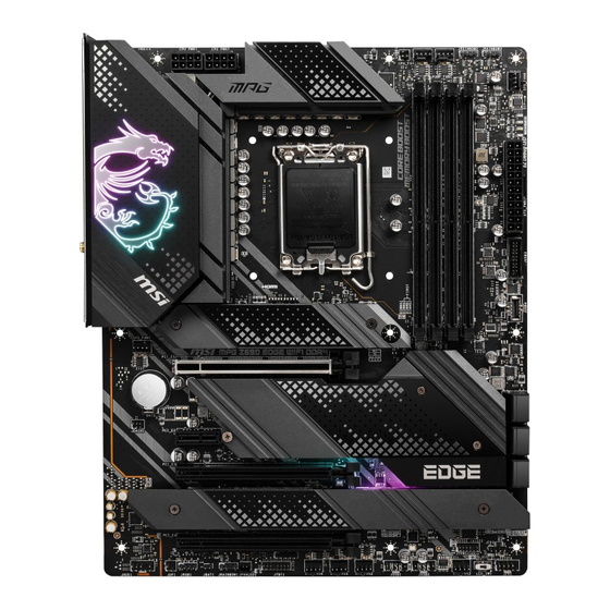
Thank you for purchasing the MSI®
MPG Z690 EDGE WIFI
motherboard. This Quick Start section provides demonstration
diagrams about how to install your computer. Some of the
installations also provide video demonstrations. Please link to the
URL to watch it with the web browser on your phone or tablet. You
may have even link to the URL by scanning the QR code.
Kurzanleitung
Danke, dass Sie das MSI®
MPG Z690 EDGE WIFI
Motherboard
gewählt haben. Dieser Abschnitt der Kurzanleitung bietet eine Demo
zur Installation Ihres Computers. Manche Installationen bieten
auch die Videodemonstrationen. Klicken Sie auf die URL, um diese
Videoanleitung mit Ihrem Browser auf Ihrem Handy oder Table
anzusehen. Oder scannen Sie auch den QR Code mit Ihrem Handy,
um die URL zu öffnen.
Présentation rapide
Merci d'avoir choisi la carte mère MSI®
MPG Z690 EDGE
WIFI.
Ce manuel fournit une rapide présentation avec des illustrations
explicatives qui vous aideront à assembler votre ordinateur. Des
tutoriels vidéo sont disponibles pour certaines étapes. Cliquez sur
le lien fourni pour regarder la vidéo sur votre téléphone ou votre
tablette. Vous pouvez également accéder au lien en scannant le QR
code qui lui est associé.
Быстрый старт
Благодарим вас за покупку материнской платы MSI®
MPG Z690
EDGE
WIFI. В этом разделе представлена информация, которая
поможет вам при сборке комьютера. Для некоторых этапов сборки
имеются видеоинструкции. Для просмотра видео, необходимо
открыть соответствующую ссылку в веб-браузере на вашем
телефоне или планшете. Вы также можете выполнить переход по
ссылке, путем сканирования QR-кода.
I
Quick Start
Advertisement
Chapters
Table of Contents

Related Manuals for MSI MPG Z690 EDGE


Summary of Contents for MSI MPG Z690 EDGE
- Page 1 Videoanleitung mit Ihrem Browser auf Ihrem Handy oder Table anzusehen. Oder scannen Sie auch den QR Code mit Ihrem Handy, um die URL zu öffnen. Présentation rapide Merci d’avoir choisi la carte mère MSI® MPG Z690 EDGE WIFI. Ce manuel fournit une rapide présentation avec des illustrations explicatives qui vous aideront à...
- Page 2 Installing a Processor/ Installation des Prozessors/ Installer un processeur/ Установка процессора Youtube ⚽ https://youtu.be/KMf9oIDsGes Quick Start...
- Page 3 Installing DDR5 memory/ Installation des DDR5-Speichers/ Installer une mémoire DDR5/ Установка памяти DDR5 Youtube ⚽ https://youtu.be/XiNmkDNZcZk DIMMA1 DIMMA2 DIMMA2 DIMMA2 DIMMB2 DIMMB1 DIMMB2 Quick Start...
- Page 4 Connecting the Front Panel Header/ Anschließen der Frontpanel-Stiftleiste/ Connecter un connecteur du panneau avant/ Подключение разъемов передней панели Youtube ⚽ http://youtu.be/DPELIdVNZUI Power LED Power Switch JFP1 Reserved HDD LED Reset Switch HDD LED + Power LED + HDD LED - Power LED - Reset Switch Power Switch...
- Page 5 Installing the Motherboard/ Installation des Motherboards/ Installer la carte mère/ Установка материнской платы Youtube ⚽ https://youtu.be/wWI6Qt51Wnc Torque: 3 kgf·cm* *3 kgf·cm = 0.3 N·m = 2.6 lbf·in Quick Start...
- Page 6 Connecting the Power Connectors/ Stromanschlüsse anschliessen/ Connecter les câbles du module d’alimentation/ Подключение разъемов питания Youtube ⚽ http://youtu.be/gkDYyR_83I4 ATX_PWR1 CPU_PWR2 CPU_PWR1 Quick Start...
- Page 7 Installing SATA Drives/ Installation der SATA-Laufwerke/ Installer le disque dur SATA/ Установка дисков SATA Youtube ⚽ http://youtu.be/RZsMpqxythc Quick Start...
- Page 8 Installing a Graphics Card/ Einbau der Grafikkarte/ Installer une carte graphique/ Установка дискретной видеокарты Youtube ⚽ http://youtu.be/mG0GZpr9w_A VIII Quick Start...
- Page 9 Connecting Peripheral Devices/ Peripheriegeräte/ Connecter un périphérique anschliessen/ Подключение периферийных устройств Quick Start...
- Page 10 Power On/ Einschalten/ Mettre sous-tension/ Включение питания Quick Start...
-
Page 11: Table Of Contents
JRAINBOW1~3: Addressable RGB LED connectors ..........32 Onboard LEDs ...................... 33 EZ Debug LED ....................... 33 LED_SW1: EZ LED Control ................... 33 JPWRLED1: LED power input ................33 Installing OS, Drivers & MSI Center ..............34 Installing Windows 10/ Windows 11 ..............34 Contents... - Page 12 Installing Drivers ....................34 MSI Center ......................34 UEFI BIOS ......................35 BIOS Setup ......................36 Entering BIOS Setup ..................... 36 BIOS User Guide ....................36 Resetting BIOS ...................... 37 Updating BIOS ....................... 37 Contents...
-
Page 13: Safety Information
Safety Information ∙ The components included in this package are prone to damage from electrostatic discharge (ESD). Please adhere to the following instructions to ensure successful computer assembly. ∙ Ensure that all components are securely connected. Loose connections may cause the computer to not recognize a component or fail to start. -
Page 14: Case Stand-Off Notification
Case stand-off notification To prevent damage to the motherboard, any unnecessary mounting stand-off between the motherboard circuits and the computer case is prohibited. The Case standoff keep out zone signs will be marked on the backside of motherboard (as shown below) to serve as a warning to user. -
Page 15: Specifications
Specifications ∙ Supports 12th Gen Intel® Core™, Pentium® Gold and Celeron® Processors* ∙ Processor socket LGA1700 * Please go to www.msi.com to get the newest support status as new processors are released. Chipset Intel® Z690 Chipset ∙ 4x DDR5 memory slots, support up to 128GB* ▪... - Page 16 Continued from previous page ∙ 6x SATA 6Gb/s ports ▪ SATA5~8 (From Z690 Chipset) ▪ SATAA~B (From ASMedia ASM1061) ∙ 4x M.2 slots (Key M) ▪ M2_1 slot (From CPU) ▫ Supports PCIe 4.0 x4 ▫ Supports 2260/ 2280/ 22110 storage devices ▪...
- Page 17 Continued from previous page ∙ Intel® Z690 Chipset ▪ 1x USB 3.2 Gen 2x2 20Gbps Type-C port on the back panel ▪ 6x USB 3.2 Gen 2 10Gbps ports (1 Type-C internal connector and 5 Type-A ports on the back panel) ▪...
- Page 18 Continued from previous page ∙ 1x 24-pin ATX main power connector ∙ 2x 8-pin ATX 12V power connectors ∙ 6x SATA 6Gb/s connectors ∙ 4x M.2 slots (M-Key) ∙ 1x USB 3.2 Gen 2 10Gbps Type-C port ∙ 1x USB 3.2 Gen 1 5Gbps connector (supports additional 2 USB 3.2 Gen 1 5Gbps ports) ∙...
- Page 19 ∙ ACPI 6.4, SMBIOS 3.4 ∙ Multi-language ∙ Drivers ∙ MSI Center ∙ Intel® Extreme Tuning Utility ∙ MSI APP Player (BlueStacks) Software ∙ Open Broadcaster Software (OBS) ∙ CPU-Z MSI GAMING ∙ Google Chrome™, Google Toolbar, Google Drive ∙ Norton™ Internet Security Solution ∙...
- Page 20 Continued from previous page ∙ Audio ▪ Audio Boost 5 ∙ Network ▪ 2.5G LAN ▪ LAN Manager ▪ Intel® WiFi ∙ Cooling ▪ All Aluminum Design ▪ Heat-pipe Design ▪ Extended Heatsink Design Special Features ▪ M.2 Shield Frozr ▪...
- Page 21 ▪ 2oz Copper thickened PCB ∙ Protection ▪ PCI-E Steel Armor ▪ Pre-installed I/O Shielding ∙ Experience ▪ MSI Center ▪ Click BIOS 5 ▪ EZ M.2 Clip ▪ Frozr AI Cooling ▪ Flash BIOS Button ▪ EZ LED Control ▪...
-
Page 22: Package Contents
Package contents Please check the contents of your motherboard package. It should contain: Motherboard MPG Z690 EDGE WIFI User manual Documentation Quick installation guide Application USB drive with drivers & utilities SATA 6G cables (2 cables/pack) Cable LED JRGB Y cable... -
Page 23: Rear I/O Panel
Rear I/O Panel Wi-Fi Antenna USB 3.2 Gen 2 connectors 10Gbps Type-A Audio Ports 2.5 Gbps LAN DisplayPort USB 2.0 Flash BIOS Button Flash BIOS Port Optical S/PDIF-Out USB 3.2 Gen 2x2 20Gbps Type-C ∙ Flash BIOS Port/ Button - Please refer to page 38 for Updating BIOS with Flash BIOS Button. -
Page 24: Realtek Audio Console
Realtek Audio Console After Realtek Audio Console is installed. You can use it to change sound settings to get better sound experience. Application Enhancement Device Selection Main Volume Connector Settings Jack Status ∙ Device Selection - allows you to select a audio output source to change the related options. - Page 25 Audio jacks to headphone and microphone diagram Audio jacks to stereo speakers diagram AUDIO INPUT Audio jacks to 7.1-channel speakers diagram AUDIO INPUT Rear Front Side Center/ Subwoofer Rear I/O Panel...
- Page 26 Installing antennas 1. Screw the antennas tight to the antenna connectors as shown below. 2. Orient the antennas. Rear I/O Panel...
-
Page 27: Overview Of Components
Overview of Components Processor Socket PUMP_FAN1 CPU_PWR2 CPU_FAN1 JRAINBOW2 CPU_PWR1 JSMB1 JRAINBOW3 SYS_FAN6 DIMMB2 DIMMB1 ATX_PWR1 DIMMA2 JUSB3 JUSB4 M2_1 DIMMA1 SYS_FAN1 M2_2 PCI_E1 M2_4 SATA▼A▲B JDASH1 PCI_E2 SATA▼7▲8 SATA▼5▲6 PCI_E3 M2_3 JTPM1 PCI_E4 JFP2 JCI1 JFP1 JRGB1 SYS_FAN3 JBAT1 JUSB2 JAUD1 LED_SW1... -
Page 28: Cpu Socket
∙ the CPU. ∙ Please retain the CPU protective cap after installing the processor. MSI will deal with Return Merchandise Authorization (RMA) requests if only the motherboard comes with the protective cap on the CPU socket. When installing a CPU, always remember to install a CPU heatsink. A CPU heatsink ∙... -
Page 29: Dimm Slots
It is recommended to use a more efficient memory cooling system for full DIMMs ∙ installation or overclocking. ∙ The stability and compatibility of installed memory module depend on installed CPU and devices when overclocking. Please refer www.msi.com for more information on compatible memory. ∙ Overview of Components... -
Page 30: Pci_E1~4: Pcie Expansion Slots
PCI_E4: PCIe 3.0 x4 (From Z690 chipset) ⚠ Important If you install a large and heavy graphics card, you need to use a tool such as MSI ∙ Gaming Series Graphics Card Bolster to support its weight to prevent deformation of the slot. -
Page 31: M2_1~4: M.2 Slots (Key M)
M2_1~4: M.2 Slots (Key M) ⚠ Important ∙ Intel® RST only supports PCIe M.2 SSD with UEFI ROM. M2_1 M2_2~4 support Intel® Optane™ Memory. ∙ M2_2 M2_4 M2_3 Installing M.2 module 1. Loosen the screws of M.2 SHIELD FROZR heatsink. 2. - Page 32 3. If there is no EZ M.2 Clip installed, please install the supplied EZ M.2 Clip kit in the M.2 slot according to your SSD length. 4. Insert your M.2 SSD into the M.2 slot at a 30-degree angle. 5. Rotate the EZ M.2 Clip to fix the M.2 SSD. 30º...
-
Page 33: Sata5~8 & Sataa~B: Sata 6Gb/S Connectors
SATA5~8 & SATAA~B: SATA 6Gb/s Connectors These connectors are SATA 6Gb/s interface ports. Each connector can connect to one SATA device. SATAB SATAA SATA8 SATA7 SATA6 SATA5 ⚠ Important Please do not fold the SATA cable at a 90-degree angle. Data loss may result during ∙... -
Page 34: Jfp1, Jfp2: Front Panel Connectors
JFP1, JFP2: Front Panel Connectors These connectors connect to the switches and LEDs on the front panel. Buzzer JFP2 Speaker Speaker - Buzzer + Buzzer - Speaker + Power LED Power Switch JFP1 Reserved HDD LED Reset Switch HDD LED + Power LED + HDD LED - Power LED -... -
Page 35: Cpu_Pwr1~2, Atx_Pwr1: Power Connectors
CPU_PWR1~2, ATX_PWR1: Power Connectors These connectors allow you to connect an ATX power supply. CPU_PWR1~2 Ground +12V Ground +12V Ground +12V Ground +12V +3.3V +3.3V +3.3V -12V Ground Ground PS-ON# Ground Ground Ground ATX_PWR1 Ground Ground PWR OK 5VSB +12V +12V +3.3V Ground... -
Page 36: Jusb4: Usb 3.2 Gen 2 Type-C Connector
JUSB4: USB 3.2 Gen 2 Type-C Connector This connector allows you to connect USB 3.2 Gen 2 10Gbps Type-C connector on the front panel. The connector possesses a foolproof design. When you connect the cable, be sure to connect it with the corresponding orientation. USB Type-C Cable JUSB4 USB Type-C port on... -
Page 37: Jusb1~2: Usb 2.0 Connectors
∙ In order to recharge your iPad,iPhone and iPod through USB ports, please install MSI® Center utility. JTPM1: TPM Module Connector This connector is for TPM (Trusted Platform Module). Please refer to the TPM security platform manual for more details and usages. -
Page 38: Cpu_Fan1, Pump_Fan1, Sys_Fan1~6: Fan Connectors
CPU_FAN1, PUMP_FAN1, SYS_FAN1~6: Fan Connectors Fan connectors can be classified as PWM (Pulse Width Modulation) Mode or DC Mode. PWM Mode fan connectors provide constant 12V output and adjust fan speed with speed control signal. DC Mode fan connectors control fan speed by changing voltage. The auto mode fan connectors can automatically detect PWM and DC mode. -
Page 39: Jci1: Chassis Intrusion Connector
JCI1: Chassis Intrusion Connector This connector allows you to connect the chassis intrusion switch cable. Normal Trigger the chassis (default) intrusion event Using chassis intrusion detector 1. Connect the JCI1 connector to the chassis intrusion switch/ sensor on the chassis. 2. -
Page 40: Jbat1: Clear Cmos (Reset Bios) Jumper
JBAT1: Clear CMOS (Reset BIOS) Jumper There is CMOS memory onboard that is external powered from a battery located on the motherboard to save system configuration data. If you want to clear the system configuration, set the jumpers to clear the CMOS memory. Keep Data Clear CMOS/ (default) -
Page 41: Jrgb1: Rgb Led Connector
(12V/G/R/B) with the maximum power rating of 3A (12V). Always turn off the power supply and unplug the power cord from the power outlet ∙ before installing or removing the RGB LED strip. Please use MSI’s software to control the extended LED strip. ∙ Overview of Components... -
Page 42: Jrainbow1~3: Addressable Rgb Led Connectors
(5V). In the case of 20% brightness, the connector supports up to 200 LEDs. ∙ Always turn off the power supply and unplug the power cord from the power outlet before installing or removing the RGB LED strip. Please use MSI’s software to control the extended LED strip. ∙ Overview of Components... -
Page 43: Onboard Leds
Onboard LEDs EZ Debug LED These LEDs indicate the debug status of the motherboard. CPU - indicates CPU is not detected or fail. DRAM - indicates DRAM is not detected or fail. VGA - indicates GPU is not detected or fail. BOOT - indicates the booting device is not detected or fail. -
Page 44: Installing Os, Drivers & Msi Center
MSI Center is an application that helps you easily optimize game settings and smoothly use content creation softwares. It also allows you to control and synchronize LED light effects on PCs and other MSI products. With MSI Center, you can customize ideal modes, monitor system performance, and adjust fan speed. -
Page 45: Uefi Bios
UEFI has many new functions and advantages that traditional BIOS cannot achieve, and it will completely replace BIOS in the future. The MSI UEFI BIOS uses UEFI as the default boot mode to take full advantage of the new chipset’s capabilities. -
Page 46: Bios Setup
* When you press F10, a confirmation window appears and it provides the modification information. Select between Yes or No to confirm your choice. BIOS User Guide If you’d like to know more instructions on setting up the BIOS, please refer to http://download.msi.com/manual/mb/Intel600BIOS.pdf or scan the QR code to access. UEFI BIOS... -
Page 47: Resetting Bios
Updating BIOS Updating BIOS with M-FLASH Before updating: Please download the latest BIOS file that matches your motherboard model from MSI website. And then save the BIOS file into the USB flash drive. Updating BIOS: 1. Switch to the target BIOS ROM by Multi-BIOS switch. Please skip this step if your motherboard doesn't has this switch. - Page 48 1. Please download the latest BIOS file that matches your motherboard model from the MSI® website. 2. Rename the BIOS file to MSI.ROM, and save it to the root of the USB storage device. 3. Connect the power supply to CPU_PWR1 and ATX_PWR1. (No need to install CPU and memory.)
- Page 49 JRAINBOW1~3: Adressierbarer RGB-LED-Streifen Anschlüsse ......32 Onboard LEDs .................... 33 EZ DEBUG LED ..................... 33 LED_SW1: EZ LED Steuerung ................33 JPWRLED1: LED Stromzufuhr ................33 Installation von OS, Treibern & MSI Center ..........34 Installation von Windows 10/ Windows 11 ............34 Inhalt...
- Page 50 Installation von Treibern ..................34 MSI Center ......................35 UEFI BIOS ....................36 BIOS Setup ......................37 Öffnen des BIOS Setups..................37 BIOS-Benutzerhandbuch..................37 Reset des BIOS ..................... 38 Aktualisierung des BIOS ..................38 Inhalt...
-
Page 51: Sicherheitshinweis
Sicherheitshinweis ∙ Die im Paket enthaltene Komponenten sind der Beschädigung durch elektrostatischen Entladung (ESD). Beachten Sie bitte die folgenden Hinweise, um die erfolgreichen Computermontage sicherzustellen. ∙ Stellen Sie sicher, dass alle Komponenten fest angeschlossen sind. Lockere Steckverbindungen können Probleme verursachen, zum Beispiel: Der Computer erkennt eine Komponente nicht oder startet nicht. -
Page 52: Hinweise Zum Gehäuseabstandshalter
Hinweise zum Gehäuseabstandshalter Um eine Beschädigung des Motherboards zu vermeiden, sind unnötige Abstandshalter zwischen den Motherboard-Schaltkreisen und dem Computergehäuse verboten.. Die Schilder „Case Standoff Keep Out Zone (Gehäuseabstandszone freihalten )“ auf der Rückseite des Motherboards (wie unten gezeigt) dienen als entsprechender Hinweis für den Anwender. -
Page 53: Spezifikationen
Spezifikationen ∙ Unterstützt Intel® Core™ der 12. Generation Prozessoren, Pentium® Gold und Celeron® Prozessoren* ∙ Prozessor Sockel LGA1700 * Bitte besuchen Sie www.msi.com, um den neuesten Support-Status zu erhalten, wenn neue Prozessoren veröffentlicht werden. Chipsatz Intel® Z690 Chipsatz ∙ 4x DDR5 Speicherplätze, aufrüstbar bis 128 GB* ▪... - Page 54 Fortsetzung der vorherigen Seite ∙ 6x SATA 6Gb/s Anschlüsse ▪ SATA5~8 Steckplatz (von Z690 Chipsatz) ▪ SATAA~B (von ASMedia ASM1061) ∙ 4x M.2 Steckplätze (Key M) ▪ M2_1 Steckplatz (von CPU) ▫ Unterstützt PCIe 4.0 x4 ▫ Unterstützt 2260/ 2280/ 22110 Speichergeräte ▪...
- Page 55 Fortsetzung der vorherigen Seite ∙ Intel® Z690 Chipsatz ▪ 1x USB 3.2 Gen 2x2 20Gbit/s Typ-C Anschluss an der rückseitigen Anschlussleiste ▪ 6x USB 3.2 Gen 2 10Gbit/s Anschlüsse (1 Typ-C interner Anschluss und 5 Typ-A Anschluss an der rückseitigen Anschlussleiste) ▪...
- Page 56 Fortsetzung der vorherigen Seite ∙ 1x 24-poliger ATX Stromanschluss ∙ 2x 8-polige ATX Stromanschlüsse ∙ 6x SATA 6Gb/s Anschlüsse ∙ 4x M.2 Steckplätze (Key M) ∙ 1x USB 3.2 Gen 2 10Gbit/s Typ-C Anschluss ∙ 1x USB 3.2 Gen 1 5Gbit/s Anschluss (unterstützt zusätzliche 2 USB 3.2 Gen 1 5Gbit/s Anschlüsse) ∙...
- Page 57 ∙ ACPI 6.4, SMBIOS 3.4 ∙ Mehrsprachenunterstützung ∙ Treiber ∙ MSI Center ∙ Intel® Extreme Tuning Utility ∙ MSI APP Player (BlueStacks) Software ∙ Open Broadcaster Software (OBS) ∙ CPU-Z MSI GAMING ∙ Google Chrome™, Google Toolbar, Google Drive ∙ Norton™ Internet Security Solution ∙...
- Page 58 Fortsetzung der vorherigen Seite ∙ Audio ▪ Audio Boost 5 ∙ Netzwerk ▪ 2.5G LAN ▪ LAN Manager ▪ Intel® WiFi ∙ Kühlung ▪ Design aus Aluminium ▪ Heatpipe zur Kühlung ▪ Erweitertes Kühlkörperdesign Besondere Funktionen ▪ M.2 Shield Frozr ▪...
- Page 59 ▪ 2oz Kupfer verdicktes PCB Funktionen ∙ Schutz ▪ PCI-E Steel Armor ▪ Vorinstallierte Anschlussblende ∙ Erfahrung ▪ MSI Center ▪ Click BIOS 5 ▪ EZ M.2 Clip ▪ Frozr AI Kühlung ▪ Flash BIOS Taste ▪ EZ LED Steuerung ▪...
-
Page 60: Packungsinhalt
Packungsinhalt Überprüfen Sie den Packungsinhalt des Mainboards. Die Packung sollte enthalten: Motherboard MPG Z690 EDGE WIFI Benutzerhandbuch Dokumentation Schnellinstallationsanleitung USB-Laufwerk mit Treibern und Anwendung Dienstprogrammen SATA 6G/s Kabel (2 Kabel pro Packung) Kabel LED JRGB Y Kabel LED JRAINBOW Kabel Wi-Fi Antenne Gehäuse-Aufkleber... -
Page 61: Rückseite E/A
Rückseite E/A Wi-Fi Antennen- USB 3.2 Gen 2 anschlüsse 10Gbit/s Typ-A Audioanschlüsse 2,5 Gbit/s LAN DisplayPort USB 2.0 Flash BIOS Taste Flash BIOS Optischer Anschluss S/PDIF- Ausgang USB 3.2 Gen 2x2 20Gbit/s Typ-C ∙ Flash BIOS Anschluss/ Taste - Auf der Seite 39 finden Sie eine Anleitung für eine BIOS-Aktualisierung per Flash BIOS Taste. -
Page 62: Realtek Audio Console
Realtek Audio Console Nach der Installation des Realtek Audio Console-Treibers, können Sie die Audioeinstellungen verändern, um ein optimales Klangerlebnis erzeugen. Optimierungen Geräteauswahl Lautstärke Anschluss Verbindungsstatus ∙ Geräteauswahl - Ermöglicht die Auswahl der Audio-Ausgangs Quelle. Das aktuell aktivierte Gerät ist mit einem Haken gekennzeichnet. ∙... - Page 63 Audiobuchsen für den Anschluss von einem Kopfhörer und Mikrofon Audiobuchsen für Stereo-Lautsprecher AUDIO INPUT Audiobuchsen für 7.1 Kanal Anlage AUDIO INPUT Rear Front Side Center/ Subwoofer Rückseite E/A...
- Page 64 Antennen installieren 1. Schrauben Sie die Antennen fest an die Antennenanschlüsse, wie gezeigt. 2. Richten Sie die Antennenspitzen aus. Rückseite E/A...
-
Page 65: Übersicht Der Komponenten
Übersicht der Komponenten Prozessor Sockel PUMP_FAN1 CPU_PWR2 CPU_FAN1 JRAINBOW2 CPU_PWR1 JSMB1 JRAINBOW3 SYS_FAN6 DIMMB2 DIMMB1 ATX_PWR1 DIMMA2 JUSB3 JUSB4 M2_1 DIMMA1 SYS_FAN1 M2_2 PCI_E1 M2_4 SATA▼A▲B JDASH1 PCI_E2 SATA▼7▲8 SATA▼5▲6 PCI_E3 M2_3 JTPM1 PCI_E4 JFP2 JCI1 JFP1 JRGB1 SYS_FAN3 JBAT1 JUSB2 JAUD1 LED_SW1... -
Page 66: Cpu Sockel
Sie jedoch bitte sicher, dass die betroffenen Komponenten mit den abweichenden Einstellungen während des Übertaktens zurecht kommen. Von jedem Versuch des Betriebes außerhalb der Produktspezifikationen kann nur abgeraten werden. MSI übernehmt keinerlei Garantie für die Schäden und Risiken, die aus einem unzulässigem Betrieb oder einem Betrieb außerhalb der Produktspezifikation resultieren. -
Page 67: Dimm Steckplätze
DIMMs oder beim Übertakten zu verwenden. Die Stabilität und Kompatibilität beim Übertakten der installierten Speichermodule ∙ sind abhängig von der installierten CPU und den installierten Geräten. ∙ Weitere Informationen zu kompatiblen Speicher finden Sie unter: www.msi.com Übersicht der Komponenten... -
Page 68: Pci_E1~4: Pcie Erweiterungssteckplätze
Wichtig Wenn Sie eine große und schwere Grafikkarte einbauen, benötigen Sie einen ∙ Grafikkarten-Stabilisator (Graphics Card Bolster) der MSI Gaming Serien der das Gewicht trägt und eine Verformung des Steckplatzes vermeidet. ∙ Für die Installation einer einzelnen PCIe x16 Erweiterungskarte mit optimaler Leistung, empfehlen wir den PCI_E1 Steckplatz zu verwenden. -
Page 69: M2_1~4: M.2 Steckplätze (Key M)
M2_1~4: M.2 Steckplätze (Key M) ⚠ Wichtig ∙ Intel® RST unterstützt nur PCIe M.2 SSD mit UEFI ROM. M2_1 M2_2~4 unterstützt Intel® Optane™ Memory ∙ M2_2 M2_4 M2_3 Installation eines M.2 Moduls 1. Lösen Sie die Schraube des M.2-SHIELD FROZR-Kühlkörpers. 2. - Page 70 3. Wenn kein EZ M.2 Clip installiert ist, installieren Sie bitte das mitgelieferte EZ M.2 Clip-Kit entsprechend Ihrer SSD-Länge im M.2-Steckplatz. 4. Stecken Sie eine M.2-SSD im 30-Grad-Winkel in den M.2-Steckplatz. 5. Drehen Sie den EZ M.2 Clip, um die M.2 SSD zu befestigen. 30º...
-
Page 71: Sata5~8 & Sataa~B: Sata 6Gb/S Anschlüsse
SATA5~8 & SATAA~B: SATA 6Gb/s Anschlüsse Dieser Anschluss basiert auf der Hochgeschwindigkeitsschnittstelle SATA 6 Gb/s. Pro Anschluss kann ein SATA Gerät angeschlossen werden. SATAB SATAA SATA8 SATA7 SATA6 SATA5 ⚠ Wichtig Knicken Sie das SATA-Kabel nicht in einem 90° Winkel. Datenverlust könnte die ∙... -
Page 72: Jfp1, Jfp2: Frontpanel-Anschlüsse
JFP1, JFP2: Frontpanel-Anschlüsse Diese Anschlüsse verbinden die Schalter und LEDs des Frontpanels. Buzzer JFP2 Speaker Speaker - Buzzer + Buzzer - Speaker + Power LED Power Switch JFP1 Reserved HDD LED Reset Switch HDD LED + Power LED + HDD LED - Power LED - Reset Switch Power Switch... -
Page 73: Cpu_Pwr1~2, Atx_Pwr1: Stromanschlüsse
CPU_PWR1~2, ATX_PWR1: Stromanschlüsse Mit diesen Anschlüssen verbinden Sie die ATX Stromstecker. CPU_PWR1~2 Ground +12V Ground +12V Ground +12V Ground +12V +3,3V +3,3V +3,3V -12V Ground Ground PS-ON# Ground Ground Ground ATX_PWR1 Ground Ground PWR OK 5VSB +12V +12V +3,3V Ground ⚠... -
Page 74: Jusb4: Usb 3.2 Gen 2 Typ-C Anschluss
JUSB4: USB 3.2 Gen 2 Typ-C Anschluss Mit diesem Anschluss können Sie den USB 3.2 Gen 2 10 Gbit/s Typ-C Anschluss auf dem Frontpanel verbinden. Der Anschluss verfügt über ein besonders sicheres Design. Wenn Sie das Kabel anschließen, müssen Sie es in der entsprechenden Ausrichtung verbinden. -
Page 75: Jusb1~2: Usb 2.0 Anschlüsse
∙ Um ein iPad, iPhone und einen iPod über USB-Anschlüsse aufzuladen, installieren Sie bitte die MSI® Center-Dienstprogramm. JTPM1: TPM Anschluss Dieser Anschluss wird für das TPM Modul (Trusted Platform Module) verwendet. Weitere Informationen über den Einsatz des optionalen TPM Modules entnehmen Sie bitte dem TPM Plattform Handbuch. -
Page 76: Cpu_Fan1, Pump_Fan1, Sys_Fan1~6: Stromanschlüsse Für Lüfter
CPU_FAN1, PUMP_FAN1, SYS_FAN1~6: Stromanschlüsse für Lüfter Diese Anschlüsse können im PWM (Pulse Width Modulation) Modus oder Spannungsmodus betrieben werden. Im PWM-Modus bieten die Lüfteranschlüsse konstante 12V Ausgang und regeln die Lüftergeschwindigkeit per Drehzahlsteuersignal. Im DC-Modus bestimmen die Lüfteranschlüsse die Lüftergeschwindigkeit durch Ändern der Spannung. -
Page 77: Jci1: Gehäusekontaktanschluss
JCI1: Gehäusekontaktanschluss Dieser Anschluss wird mit einem Kontaktschalter verbunden Normal Löse den (Standardwert) Gehäuseeingriff aus Gehäusekontakt-Detektor verwenden 1. Schließen Sie den JCI1 -Anschluss am Gehäusekontakt-Schalter/ Sensor am Gehäuse an. 2. Schließen Sie die Gehäuseabdeckung. 3. Gehen Sie zu BIOS > SETTINGS > Security > Chassis Intrusion Configuration. 4. -
Page 78: Jbat1: Clear Cmos Steckbrücke (Reset Bios)
JBAT1: Clear CMOS Steckbrücke (Reset BIOS) Der Onboard CMOS Speicher (RAM) wird durch eine externe Spannungsversorgung durch eine Batterie auf dem Motherboard versorgt, um die Daten der Systemkonfiguration zu speichern. Wenn Sie die Systemkonfiguration löschen wollen, müssen Sie die Steckbrücke für kurze Zeit umsetzen. Daten CMOS-Daten beibehalten... -
Page 79: Jrgb1: Rgb Led Anschluss
R/B) mit der maximalen Leistung von 3 A (12 V) Schalten Sie die Stromversorgung aus und ziehen Sie das Netzkabel ab, bevor Sie ∙ die RGB-LED-Streifen ein- und ausbauen. Bitte verwenden Sie die MSI-Software zur Steuerung des LED-Leuchtstreifens. ∙ Übersicht der Komponenten... -
Page 80: Jrainbow1~3: Adressierbarer Rgb-Led-Streifen Anschlüsse
3 A (5 V). Bei einer Helligkeit von 20 Prozent unterstützt dieser Anschluss bis zu 200 LEDs. Schalten Sie die Stromversorgung aus und ziehen Sie das Netzkabel ab, bevor Sie ∙ die RGB-LED-Streifen ein- und ausbauen. Bitte verwenden Sie die MSI-Software zur Steuerung des LED-Leuchtstreifens. ∙ Übersicht der Komponenten... -
Page 81: Onboard Leds
Onboard LEDs EZ DEBUG LED Diese LEDs zeigen den Debug-Status des Motherboards an. CPU - CPU wird nicht erkannt oder ist fehlerhaft. DRAM - DRAM wird nicht erkannt oder ist fehlerhaft. VGA - GPU wird nicht erkannt oder ist fehlerhaft BOOT - Boot-Gerät wird nicht erkannt oder ist fehlerhaft. -
Page 82: Installation Von Os, Treibern & Msi Center
Installation von OS, Treibern & MSI Center Laden Sie die neuesten Treiber und und Dienstprogramme von www.msi.com herunter und aktualisieren Sie sie. Installation von Windows 10/ Windows 11 1. Schalten Sie den Computer ein. 2. Legen Sie die Windows 10/ Windows 11-Installations-Disk oder das USB- Flashlaufwerk in das optisches Laufwerk. -
Page 83: Msi Center
MSI Center MSI Center ist eine Anwendung, mit der Sie die Spieleinstellungen einfach optimieren und die Software zur Erstellung von Inhalten einstellen können. Außerdem können Sie LED-Lichteffekte in PCs und anderen MSI-Produkten steuern und synchronisieren. Mit MSI Center können Sie ideale Modi einstellen, die Systemleistung überwachen und die Lüftergeschwindigkeit anpassen. -
Page 84: Uefi Bios
UEFI BIOS Das MSI UEFI-BIOS ist mit der UEFI-Architektur (Unified Extensible Firmware Interface) kompatibel. Das UEFI-BIOS hat viele neue Funktionen und besitzt Vorteile, die das traditionelle BIOS nicht bieten kann. Es wird zukünftige PCs und Geräte, die der UEFI-Firmware-Architektur entsprechen, vollständig unterstützen. Das MSI UEFI-BIOS verwendet UEFI als Standard-Startmodus, um die Funktionen des neuen Chipsatzes voll auszunutzen. -
Page 85: Bios Setup
* Beim Drücken der F10 Taste wird das Fenster zum Speichern der Einstellungen angezeigt. Wählen Sie Yes, um die Wahl zu bestätigen, oder No, um die derzeitige Einstellung beizubehalten. BIOS-Benutzerhandbuch Wenn Sie weitere Anweisungen zur BIOS-Einrichtung wünschen, lesen Sie bitte http://download.msi.com/manual/mb/Intel600BIOSde.pdf oder scannen Sie den QR-Code. UEFI BIOS... -
Page 86: Reset Des Bios
Aktualisierung des BIOS mit dem M-FLASH-Programm Vorbereitung: Laden Sie bitte die neueste BIOS Version, die dem Motherboard-Modell entspricht, von der offiziellen MSI Website herunter. und speichern Sie die BIOS-Datei auf USB- Flash-Laufwerk. BIOS-Aktualisierungsschritte: 1. Wechseln Sie mit dem Multi-BIOS-Switch zum Ziel-BIOS-ROM. Überspringen Sie diesen Schritt, wenn Ihr Motherboard diesen Schalter nicht hat. - Page 87 1. Laden Sie bitte die neueste BIOS Version, die das Modell des Motherboards entspricht, von der offiziellen MSI® Website. 2. Benennen die BIOS-Datei im MSI.ROM um und speichern Sie die Datei im Root- Verzeichnis des USB 2.0-Speichermedien. 3. Verbinden Sie die Stromversorgung an dem CPU_PWR1 und ATX_PWR1-Stecker.
- Page 88 NOTE...
- Page 89 EZ Debug LED ....................... 33 LED_SW1 : Contrôle EZ LED ................33 JPWRLED1 : Indicateur LED de l’entrée d’alimentation ........33 Installer OS, Pilotes et MSI Center ..............34 Installer Windows 10/ Windows 11 ..............34 Installer les pilotes ....................34 MSI Center ......................
- Page 90 UEFI BIOS ......................36 Configuration du BIOS ..................37 Entrer dans la configuration du BIOS ..............37 Guide d’utilisation du BIOS ................... 37 Réinitialiser le BIOS....................38 Mettre le BIOS à jour .................... 38 Table des matières...
-
Page 91: Informations De Sécurité
Informations de sécurité ∙ Les composants dans l’emballage peuvent être endommagés par des décharges électrostatiques (ESD). Pour vous assurer de correctement monter votre ordinateur, veuillez vous référer aux instructions ci-dessous. ∙ Assurez-vous de bien connecter tous les composants. En cas de mauvaise connexion, il se peut que l’ordinateur ne reconnaisse pas le composant et que le démarrage échoue. -
Page 92: Avertissement Pour L'installation Des Entretoises
Avertissement pour l’installation des entretoises Pour éviter d’endommager la carte mère, il est interdit d’installer des entretoises inutiles entre le circuit de la carte mère et le boîtier de l’ordinateur. Les signes de zone interdite (Keep Out Zone) sont marqués à l’arrière de la carte mère (comme indiqué... -
Page 93: Spécifications
∙ Support des processeurs Intel® Core™ de 12ème génération, Pentium® Gold et Celeron®* ∙ Socket LGA1700 * Veuillez vous rendre sur le site www.msi.com pour obtenir la dernière liste des modèles supportés à mesure que de nouveaux processeurs sont introduits sur le marché. - Page 94 Suite du tableau sur la page précédente ∙ 6 x ports SATA 6 Gb/s ▪ SATA5~8 (depuis chipset Z690) ▪ SATAA~B (depuis ASMedia ASM1061) ∙ 4 x slots M.2 (Touche M) ▪ Slot M2_1 (depuis CPU) ▫ Support PCIe 4.0 x4 ▫...
- Page 95 Suite du tableau sur la page précédente ∙ Chipset Intel® Z690 ▪ 1 x port USB 3.2 Gen 2x2 20 Gb/s Type-C sur le panneau arrière ▪ 6 x ports USB 3.2 Gen 2 10 Gb/s (1 connecteur interne Type-C et 5 ports Type-A sur le panneau arrière) ▪...
- Page 96 Suite du tableau sur la page précédente ∙ 1 x connecteur d’alimentation principal ATX à 24 broches ∙ 2 x connecteurs d’alimentation ATX 12 V à 8 broches ∙ 6 x connecteurs SATA 6 Gb/s ∙ 4 x slots M.2 (Touche M) ∙...
- Page 97 ∙ ACPI 6.4, SMBIOS 3.4 ∙ Multilingue ∙ Pilotes ∙ MSI Center ∙ Intel® Extreme Tuning Utility ∙ MSI APP Player (BlueStacks) Logiciel ∙ Open Broadcaster Software (OBS) ∙ CPU-Z MSI GAMING ∙ Google Chrome™, Google Toolbar, Google Drive ∙ Norton™ Internet Security Solution ∙...
- Page 98 Suite du tableau sur la page précédente ∙ Audio ▪ Audio Boost 5 ∙ Network ▪ 2,5 G LAN ▪ LAN Manager ▪ Intel® WiFi ∙ Cooling ▪ All Aluminum Design ▪ Heat-pipe Design ▪ Extended Heatsink Design Fonctions spéciales ▪...
- Page 99 ▪ 2oz Copper thickened PCB ∙ Protection ▪ PCI-E Steel Armor ▪ Pre-installed I/O Shielding ∙ Expérience ▪ MSI Center ▪ Click BIOS 5 ▪ EZ M.2 Clip ▪ Frozr AI Cooling ▪ Bouton Flash BIOS ▪ EZ LED Control ▪...
-
Page 100: Contenu
Contenu Vérifiez tous les articles dans le carton d’emballage de votre carte mère. L’emballage doit contenir : Carte mère MPG Z690 EDGE WIFI Manuel d’utilisation Documentation Guide d’installation rapide Application Clé USB avec pilotes et utilitaires Câble SATA 6 G (2 câbles/paquet) Câble... -
Page 101: Panneau Arrière Entrée/Sortie
Panneau arrière Entrée/Sortie Connecteurs USB 3.2 Gen 2 d'antenne Wi-Fi 10 Gb/s Type-A Ports audio 2,5 Gb/s LAN DisplayPort USB 2.0 Bouton Flash BIOS Port Flash BIOS Sortie S/PDIF optique USB 3.2 Gen 2x2 20 Gb/s Type-C ∙ Port/Bouton Flash BIOS - Veuillez vous référer à la page 39 pour la mise à jour du BIOS avec Bouton Flash BIOS. -
Page 102: Realtek Audio Console
Realtek Audio Console Après l’installation de Realtek Audio Console, vous pouvez l’utiliser pour modifier les paramètres du son afin d’obtenir une meilleure expérience sonore. Amélioration d’application Sélection du périphérique Volume principal Paramètres du connecteur État des prises Jack ∙ Sélection du périphérique - vous permet de sélectionner une source de sortie audio pour en modifier les paramètres. - Page 103 Illustration de l’utilisation des ports audio dédiés au casque et au microphone Illustration de l’utilisation du port audio dédié aux haut-parleurs AUDIO INPUT Illustration de l’utilisation des ports audio dédiés aux haut-parleurs 7.1 AUDIO INPUT Rear Front Side Center/ Subwoofer Panneau arrière Entrée/Sortie...
- Page 104 Installation des antennes 1. Vissez fermement les antennes aux connecteurs dédiés, comme illustré ici. 2. Orientez les antennes. Panneau arrière Entrée/Sortie...
-
Page 105: Vue D'ensemble Des Composants
Vue d’ensemble des composants Scoket processeur PUMP_FAN1 CPU_PWR2 CPU_FAN1 JRAINBOW2 CPU_PWR1 JSMB1 JRAINBOW3 SYS_FAN6 DIMMB2 DIMMB1 ATX_PWR1 DIMMA2 JUSB3 JUSB4 M2_1 DIMMA1 SYS_FAN1 M2_2 PCI_E1 M2_4 SATA▼A▲B JDASH1 PCI_E2 SATA▼7▲8 SATA▼5▲6 PCI_E3 M2_3 JTPM1 PCI_E4 JFP2 JCI1 JFP1 JRGB1 SYS_FAN3 JBAT1 JUSB2 JAUD1... -
Page 106: Socket Processeur
Cette carte mère supporte l’overclocking. Néanmoins, veuillez vous assurer que vos ∙ composants soient capables de tolérer l’overclocking. Prenez note que l’utilisation au-delà des spécifications du constructeur n’est pas recommandée. MSI® ne garantit pas les dommages et risques causés par les utilisations non prévues dans les spécifications du produit. -
Page 107: Slots Dimm
La stabilité et la compatibilité du module de mémoire lors de l’overclocking ∙ dépendent du processeur et des périphériques installés. Veuillez vous référer au site www.msi.com pour plus d’informations sur la mémoire ∙ compatible. Vue d’ensemble des composants... -
Page 108: Pci_E1~4 : Slots D'extension Pcie
Important Si vous installez une carte graphique lourde, il vous faut utiliser un outil comme ∙ la barre de support MSI Gaming Series pour supporter son poids et pour éviter la déformation du slot. ∙ Si vous choisissez d’installer une seule carte d’extension PCIe x16, nous vous recommandons d’utiliser le slot PCI_E1 pour profiter de performances optimales. -
Page 109: M2_1~4 : Slots M.2 (Touche M)
M2_1~4 : Slots M.2 (Touche M) ⚠ Important ∙ La technologie Intel® RST supporte uniquement un SSD M.2 PCIe avec une mémoire UEFI ROM. M2_1 Les slots M2_2~4 supportent Intel® Optane™ ∙ Memory. M2_2 M2_4 M2_3 Installation du module M.2 1. - Page 110 3. Si aucun clip EZ M.2 n’est installé, veuillez installer le kit de clips EZ M.2 fourni dans le slot M.2 selon la longueur du SSD. 4. Insérez votre SSD M.2 dans le slot M.2 à un angle de 30 degrés. 5.
-
Page 111: Sata5~8 & Sataa~B : Connecteurs Sata 6 Gb/S
SATA5~8 & SATAA~B : Connecteurs SATA 6 Gb/s Ces connecteurs utilisent une interface SATA 6 Gb/s. Chaque connecteur peut être relié à un appareil SATA. SATAB SATAA SATA8 SATA7 SATA6 SATA5 ⚠ Important Veuillez ne pas plier les câbles SATA à 90° car cela pourrait entraîner une perte de ∙... -
Page 112: Jfp1, Jfp2 : Connecteurs De Panneau Avant
JFP1, JFP2 : Connecteurs de panneau avant Ces connecteurs se lient aux interrupteurs et indicateurs LED du panneau avant. Buzzer JFP2 Speaker Speaker - Buzzer + Buzzer - Speaker + Power LED Power Switch JFP1 Reserved HDD LED Reset Switch HDD LED + Power LED + HDD LED -... -
Page 113: Cpu_Pwr1~2, Atx_Pwr1 : Connecteurs D'alimentation
CPU_PWR1~2, ATX_PWR1 : Connecteurs d’alimentation Ces connecteurs vous permettent de relier une alimentation ATX. CPU_PWR1~2 Ground +12V Ground +12V Ground +12V Ground +12V +3.3V +3.3V +3.3V -12V Ground Ground PS-ON# Ground Ground Ground ATX_PWR1 Ground Ground PWR OK 5VSB +12V +12V +3.3V Ground... -
Page 114: Jusb4 : Connecteur Usb 3.2 Gen 2 Type-C
JUSB4 : Connecteur USB 3.2 Gen 2 Type-C Ce connecteur vous permet de relier un connecteur USB 3.2 Gen 2 10 Gb/s Type-C sur le panneau avant. Pour plus de sécurité, ce connecteur a été conçu pour offrir une excellente robustesse. Quand vous connectez le câble, assurez-vous de le brancher dans le bon sens. -
Page 115: Jusb1~2 : Connecteurs Usb 2.0
∙ Pour recharger votre iPad, iPhone et iPod par l’intermédiaire d’un port USB, veuillez installer l’utilitaire MSI® Center. JTPM1 : Connecteur de module TPM Ce connecteur est relié à un module TPM (Trusted Platform Module). Veuillez vous référer au manuel du module TPM pour plus d’informations. -
Page 116: Cpu_Fan1, Pump_Fan1, Sys_Fan1~6 : Connecteurs De Ventilateur
CPU_FAN1, PUMP_FAN1, SYS_FAN1~6 : Connecteurs de ventilateur Les connecteurs de ventilateur peuvent être utilisés en mode PWM (Pulse Width Modulation) et en mode DC. En mode PWM, les connecteurs fournissent une sortie de 12 V constante et ajustent la vitesse du ventilateur avec un signal de contrôle de vitesse. -
Page 117: Jci1 : Connecteur Intrusion Châssis
JCI1 : Connecteur intrusion châssis Ce connecteur est relié à un câble d’interrupteur intrusion châssis. Normal Commencer l’activité (défaut) instrusion châssis Utilisation du détecteur d’intrusion châssis 1. Reliez le connecteur JCI1 à l’interrupteur ou au capteur d’intrusion châssis situé sur le boîtier du PC. 2. -
Page 118: Jbat1 : Cavalier Clear Cmos (Réinitialiser Le Bios)
JBAT1 : Cavalier Clear CMOS (Réinitialiser le BIOS) Une mémoire CMOS est intégrée et est alimentée en externe par une batterie située sur la carte mère afin de conserver les données de configuration système. Si vous souhaitez nettoyer la configuration du système, réglez le cavalier pour effacer la mémoire CMOS. -
Page 119: Jrgb1 : Connecteur Led Rgb
Avant d’installer ou de retirer le ruban LED RGB, veillez à toujours éteindre ∙ l’alimentation et à débrancher le câble d’alimentation de la prise électrique. Veuillez utiliser un logiciel MSI dédié pour contrôler le ruban d’extension LED. ∙ Vue d’ensemble des composants... -
Page 120: Jrainbow1~3 : Connecteurs Led Rgb Adressables
Avant d’installer ou de retirer le ruban LED RGB, veillez à toujours éteindre l’alimentation et à débrancher le câble d’alimentation de la prise électrique. Veuillez utiliser un logiciel MSI dédié pour contrôler le ruban d’extension LED. ∙ Vue d’ensemble des composants... -
Page 121: Led Embarquées
LED embarquées EZ Debug LED Ces LEDs indiquent l’état de débogage de la carte mère. CPU - indique que le CPU n’est pas détecté ou que son initialisation a échoué. DRAM - indique que la mémoire DRAM n’est pas détectée ou que son initialisation a échoué. VGA - indique que le GPU n’est pas détecté... -
Page 122: Installer Os, Pilotes Et Msi Center
Installer OS, Pilotes et MSI Center Veuillez vous référer au site www.msi.com pour télécharger et mettre à jour les derniers utilitaires et pilotes. Installer Windows 10/ Windows 11 1. Allumez l’ordinateur. 2. Insérez le disque ou la clé USB d’installation de Windows 10/ Windows 11 dans votre ordinateur. -
Page 123: Msi Center
MSI Center MSI Center est une application qui vous aide à optimiser facilement les paramètres de jeu et à utiliser les logiciels de création de contenu de manière intuitive. Elle vous permet également de contrôler et de synchroniser les effets de lumière LED sur les PC et autres produits MSI. -
Page 124: Uefi Bios
BIOS traditionnel. Le BIOS UEFI est ainsi voué à totalement remplacer le BIOS traditionnel à l’avenir. Le BIOS UEFI de MSI utilise UEFI comme mode de démarrage par défaut pour profiter au maximum des capacités du nouveau chipset. -
Page 125: Configuration Du Bios
Choisissez entre Oui et Non pour confirmer. Guide d’utilisation du BIOS Si vous souhaitez en savoir plus sur la configuration du BIOS, veuillez vous référer au fichier http://download.msi.com/manual/mb/Intel600BIOSfr.pdf ou scannez le code QR pour y accéder. UEFI BIOS... -
Page 126: Réinitialiser Le Bios
Avant la mise à jour : Veuillez télécharger la dernière version du BIOS compatible à votre carte mère sur le site MSI. Ensuite, veuillez sauvegarder le profil BIOS sur la clé USB. Mettre le BIOS à jour : 1. Accédez au BIOS ROM voulu avec le commutateur Multi-BIOS. Ignorez cette étape si votre carte mère ne possède pas ce commutateur. - Page 127 1. Veuillez télécharger la dernière version du BIOS compatible à votre carte mère sur le site MSI®. 2. Renommez le profil BIOS en MSI.ROM et enregistrez-le à la racine de la clé USB. 3. Connectez l’alimentation aux connecteurs CPU_PWR1 et ATX_PWR1. (Pas besoin d’installer le processeur et la mémoire.)
- Page 128 NOTE...
- Page 129 JRAINBOW1~3: Разъемы адресных RGB LED ............ 32 Встроенные индикаторы ................... 33 Индикаторы отладки EZ ..................33 LED_SW1: Переключатель управления индикаторами ........33 JPWRLED1: Индикатор подключения питания ..........33 Установка ОС, драйверов и MSI Center ............34 Установка Windows 10/ Windows 11 ..............34 Содержание...
- Page 130 Установка драйверов ..................34 MSI Center ......................34 UEFI BIOS ......................35 Настройка BIOS....................36 Вход в настройки BIOS ..................36 Инструкции по настройке BIOS ................36 Сброс BIOS ......................37 Обновление BIOS ....................37 Содержание...
-
Page 131: Безопасное Использование Продукции
Безопасное использование продукции ∙ Компоненты, входящие в комплект поставки могут быть повреждены статическим электричеством. Для успешной сборки компьютера, пожалуйста, следуйте указаниям ниже. ∙ Убедитесь, что все компоненты компьютера подключены должным образом. Ослабленные соединения компонентов могут привести как к сбоям в работе, так и полной... -
Page 132: Уведомление О Стойках Для Крепления Материнской Платы
Уведомление о стойках для крепления материнской платы Во избежание повреждения материнской платы, запрещается устанавливать любые ненужные стойки в зонах электрических дорожек материнской платы для крепления ее в корпусе компьютера. Знаки «Case standoff keep out zone» (зона, где запрещается устанавливать стойки) отмечены на задней стороне материнской платы... -
Page 133: Технические Характеристики
Технические характеристики ∙ Поддержка процессоров Intel® Core™ 12-го поколения, Pentium® Gold и Celeron® Процессор ∙ Процессорный сокет LGA1700 * Обратитесь www.msi.com, чтобы получить последнюю информацию о поддержке новых процессоров. Чипсет Intel® Z690 ∙ 4x слота памяти DDR5 с поддержкой до 128ГБ* ▪... - Page 134 Продолжение с предыдущей страницы ∙ 6x портов SATA 6Гб/с ▪ SATA5~8 (от чипсета Z690) ▪ SATAA~B (от ASMedia ASM1061) ∙ 4x разъема M.2 (Ключ M) ▪ Разъем M2_1 (от процессоров) ▫ Поддержка PCIe 4.0 x4 ▫ Поддержка накопителей 2260/ 2280 /22110 ▪...
- Page 135 Продолжение с предыдущей страницы ∙ Контроллер Intel® Z690 ▪ 1x порт USB 3.2 Gen 2x2 20Гбит/с Type-C на задней панели ▪ 6x портов USB 3.2 Gen 2 10Гбит/с (1 порт Type-C и 5 портов Type-A на задней панели) ▪ 2x порта USB 2.0 Type-A на задней панели ▪...
- Page 136 Продолжение с предыдущей страницы ∙ 1x 24-контактный разъем питания ATX ∙ 2x 8-контактных разъема питания ATX 12В ∙ 6x разъемов SATA 6Гб/с ∙ 4x разъема M.2 (Ключ M) ∙ 1x порт USB 3.2 Gen 2 10Гб/с Type-C ∙ 1x разъем USB 3.2 Gen 1 5Гб/с (поддержка 2-х дополнительных...
- Page 137 ∙ ACPI 6.4, SMBIOS 3.4 ∙ Мультиязычный интерфейс ∙ Драйверы ∙ MSI Center ∙ Intel® Extreme Tuning Utility ∙ MSI APP Player (BlueStacks) Программное обеспечение ∙ Open Broadcaster Software (OBS) ∙ CPU-Z MSI GAMING ∙ Google Chrome™, Google Toolbar, Google Drive ∙...
- Page 138 Продолжение с предыдущей страницы ∙ Аудио ▪ Audio Boost 5 ∙ Сеть ▪ 2.5G LAN ▪ LAN Manager ▪ Intel® WiFi ∙ Охлаждение ▪ All Aluminum Design ▪ Heat-pipe Design ▪ Extended Heatsink Design Эксклюзивные функции ▪ M.2 Shield Frozr ▪...
- Page 139 ∙ Защита ▪ PCI-E Steel Armor ▪ Предустановленная заглушка материнской платы на заднюю панель ∙ Опыт использования ▪ MSI Center ▪ Click BIOS 5 ▪ EZ M.2 Clip ▪ Frozr AI Cooling ▪ Кнопка Flash BIOS ▪ EZ LED Control ▪...
-
Page 140: Комплект Поставки
Комплект поставки Проверьте комплект поставки материнской платы. В него должны входить следующие элементы: Материнская плата MPG Z690 EDGE WIFI Руководство пользователя Документы Руководство по быстрой установке Диск с утилитами USB флэш-диск с драйверами и утилитами Кабели SATA 6Гб/с (2 шт./уп.) Кабели... -
Page 141: Задняя Панель Портов Ввода/ Вывода
Задняя панель портов ввода/ вывода Разъемы USB 3.2 Gen 2 антенны Wi-Fi 10Гб/с Type-A Порты Аудио LAN 2.5 Гб / с DisplayPort USB 2.0 Кнопка Flash BIOS Порт Flash BIOS Оптический S/PDIF-Out USB 3.2 Gen 2x2 20Гб/с Type-C ∙ Порт/Кнопка Flash BIOS – Обратитесь к странице 38 для получения информации об... -
Page 142: Realtek Audio Console
Realtek Audio Console После установки Realtek Audio Console вы можете использовать его для изменения параметров звука, чтобы улучшить качество звука. Дополнительные эффекты Выбор устройства Мастер- громкость Настройки подключений Состояние разъемов ∙ Выбор устройства – позволяет выбрать источник аудио выхода и изменить соответствующие... - Page 143 Подключение наушников и микрофона Подключение внешнего стерео усилителя (колонок) AUDIO INPUT Подключение звуковой системы 7.1 AUDIO INPUT Rear Front Side Center/ Subwoofer Задняя панель портов ввода/ вывода...
- Page 144 Установка антенн 1. Прикрутите антенну к разъему антенны WiFi, как показано на рисунке ниже. 2. Отрегулируйте угол наклона антенны. Задняя панель портов ввода/ вывода...
-
Page 145: Компоненты Материнской Платы
Компоненты материнской платы Процессорный сокет PUMP_FAN1 CPU_PWR2 CPU_FAN1 JRAINBOW2 CPU_PWR1 JSMB1 JRAINBOW3 SYS_FAN6 DIMMB2 DIMMB1 ATX_PWR1 DIMMA2 JUSB3 JUSB4 M2_1 DIMMA1 SYS_FAN1 M2_2 PCI_E1 M2_4 SATA▼A▲B JDASH1 PCI_E2 SATA▼7▲8 SATA▼5▲6 PCI_E3 M2_3 JTPM1 PCI_E4 JFP2 JCI1 JFP1 JRGB1 SYS_FAN3 JBAT1 JUSB2 JAUD1 LED_SW1... -
Page 146: Процессорный Сокет
питания. ∙ Пожалуйста, сохраните защитную крышку процессорного сокета после установки процессора. Любые возможные гарантийные случаи, связанные с работой материнской платы, MSI® будет рассматривать только, при наличии защитной крышки на процессорном сокете. ∙ При установке процессора обязательно установите процессорный кулер. Кулер, представляющий... -
Page 147: Слоты Dimm
При установке памяти во все слоты, а также при ее разгоне, рекомендуется использовать более эффективную систему охлаждения памяти. Совместимость и стабильность работы установленных модулей памяти при ∙ разгоне зависит от установленного процессора и других устройств. Дополнительную информацию о совместимых модулях памяти можно найти на ∙ веб-сайте www.msi.com. Компоненты материнской платы... -
Page 148: Pci_E1~4: Слоты Расширения Pcie
⚠ Внимание! При установке массивной видеокарты, необходимо использовать такой ∙ инструмент, как MSI Gaming Series Graphics Card Bolster для поддержки веса графической карты и во избежание деформации слота. ∙ Для установки одной карты расширения PCIe x16 с оптимальной производительностью рекомендуется использовать слот PCI_E1. -
Page 149: M2_1~4: Разъемы M.2 (Ключ M)
M2_1~4: Разъемы M.2 (Ключ M) ⚠ Внимание! ∙ Технология Intel® RST только поддерживает PCIe M.2 SSD с UEFI ROM. M2_1 Разъемы M2_2~4 поддерживают память Intel® ∙ Optane™. M2_2 M2_4 M2_3 Установка модуля M.2 1. Удалите винты для радиатора M.2 SHIELD FROZR. 2. - Page 150 3. Если зажим EZ M.2 не установлен, установите прилагаемый комплект зажима EZ M.2 в слот M.2 в соответствии с длиной твердотельного накопителя. 4. Вставьте M.2 SSD в разъем М.2 под углом 30 градусов. 5. Поверните зажим EZ M.2, чтобы зафиксировать M.2 SSD. 30º...
-
Page 151: Sata5~8 & Sataa~B: Разъемы Sata 6Гб/С
SATA5~8 & SATAA~B: Разъемы SATA 6Гб/с Эти разъемы представляют собой интерфейсные порты SATA 6Гб/с. К каждому порту можно подключить одно устройство SATA. SATAB SATAA SATA8 SATA7 SATA6 SATA5 ⚠ Внимание! Избегайте перегибов кабеля SATA под прямым углом. В противном случае, ∙... -
Page 152: Jfp1, Jfp2: Разъемы Передней Панели
JFP1, JFP2: Разъемы передней панели Эти разъемы служат для подключения кнопок и светодиодных индикаторов, расположенных на передней панели. Buzzer JFP2 Speaker Speaker - Buzzer + Buzzer - Speaker + Power LED Power Switch JFP1 Reserved HDD LED Reset Switch HDD LED + Power LED + HDD LED - Power LED -... -
Page 153: Cpu_Pwr1~2, Atx_Pwr1: Разъемы Питания
CPU_PWR1~2, ATX_PWR1: Разъемы питания Данные разъемы предназначены для подключения блока питания ATX. CPU_PWR1~2 Ground +12V Ground +12V Ground +12V Ground +12V +3.3V +3.3V +3.3V -12V Ground Ground PS-ON# Ground Ground Ground ATX_PWR1 Ground Ground PWR OK 5VSB +12V +12V +3.3V Ground ⚠... -
Page 154: Jusb4: Разъем Usb 3.2 Gen 2 Type-C
JUSB4: Разъем USB 3.2 Gen 2 Type-C Данный разъем предназначен для подключения портов 3.2 Gen 2 10Гб/с Type-C на передней панели. Данный коннектор имеет защиту от неправильного подключения. При подключении кабеля убедитесь, что коннектор сориентирован правильно относительно разъема. Кабель USB JUSB4 Type-C Порт... -
Page 155: Jusb1~2: Разъемы Usb 2.0
контакты VCC и земли. ∙ Для того, чтобы зарядить ваш iPad, iPhone и iPod через порты USB, пожалуйста, установите утилиту MSI® Center. JTPM1: Разъем модуля ТРМ Данный разъем используется для подключения модуля ТРМ (Trusted Platform Module). Дополнительные сведения см. в описании модуля ТРМ. -
Page 156: Cpu_Fan1, Pump_Fan1, Sys_Fan1~6: Разъемы Вентиляторов
CPU_FAN1, PUMP_FAN1, SYS_FAN1~6: Разъемы вентиляторов Разъемы вентиляторов можно разделить на два типа: с PWM (Pulse Width Modulation) управлением и управлением постоянным током. Разъемы вентиляторов с PWM управлением имеют контакт с постоянным напряжением 12В, а также контакт с сигналом управления скоростью вращения. Управление скоростью... -
Page 157: Jci1: Разъем Датчика Открытия Корпуса
JCI1: Разъем датчика открытия корпуса К этому разъему подключается кабель от датчика открытия корпуса. Нормально Разрешить запись по (По умолчанию) событию открытия корпуса Использование датчика открытия корпуса 1. Подключите датчик открытия корпуса к разъему JCI1. 2. Закройте крышку корпуса. 3. Войдите в BIOS > SETTINGS > Security > Chassis Intrusion Configuration. 4. -
Page 158: Jbat1: Джампер Очистки Данных Cmos (Сброс Bios)
JBAT1: Джампер очистки данных CMOS (Сброс BIOS) На плате установлена CMOS память с питанием от батарейки для хранения данных о конфигурации системы. Для сброса конфигурации системы (очистки данных CMOS памяти), воспользуйтесь этим джампером. Сохранение данных Очистка данных/ (По умолчанию) Сброс BIOS Сброс... -
Page 159: Jrgb1: Разъем Rgb Led
∙ лент (12В/G/R/B) длиной до 2 метров с максимальной мощностью 3А (12В). Перед установкой или заменой светодиодных лент RGB, необходимо полностью ∙ обесточить систему и отключить кабель питания. Используйте утилиту MSI для управления удлинительными светодиодными ∙ лентами. Компоненты материнской платы... -
Page 160: Jrainbow1~3: Разъемы Адресных Rgb Led
яркость подсветки установлена на 20%, к данному разъему можно подключить до 200 светодиодов. Перед установкой или заменой светодиодных лент RGB, необходимо полностью ∙ обесточить систему и отключить кабель питания. Используйте утилиту MSI для управления удлинительными светодиодными ∙ лентами. Компоненты материнской платы... -
Page 161: Встроенные Индикаторы
Встроенные индикаторы Индикаторы отладки EZ Данные светодиоды показывают состояния отладки материнской платы. CPU - процессор не обнаружен или поврежден. DRAM - память DRAM не обнаружена или повреждена. VGA - видеокарта не обнаружена или повреждена. BOOT - устройство загрузки не обнаружено или повреждено. -
Page 162: Установка Ос, Драйверов И Msi Center
7. Следуйте инструкциям на экране, чтобы установить Windows 10/ Windows 11. Установка драйверов 1. Загрузите компьютер в Windows 10/ Windows 11. 2. Вставьте USB флэш-диск с драйверами MSI® USB Drive в привод для оптических дисков. 3. Нажмите всплывающее окно Select to choose what happens with this disc и... -
Page 163: Uefi Bios
Interface). Прошивка UEFI имеет множество новых функций и преимуществ, которые не поддерживаются традиционным BIOS. UEFI полностью заменит традиционный BIOS в будущем. Чтобы использовать полный функционал нового чипсета, режимом загрузки по умолчанию для MSI UEFI BIOS является UEFI. ⚠ Внимание! Термин BIOS в этом руководстве пользователя относится к UEFI BIOS, если не... -
Page 164: Настройка Bios
Ctrl+F: Вход в страницу поиска * При нажатии клавиши F10 появится информационное окно. Выберите Yes или No, чтобы подтвердить выбор. Инструкции по настройке BIOS Для получения подробной информации о инсрукцииях по настройке BIOS, обратитесь к http://download.msi.com/manual/mb/Intel600BIOSru.pdf или отсканируйте QR-код и откройте веб-сайт. UEFI BIOS... -
Page 165: Сброс Bios
джампер очистки данных CMOS. Обновление BIOS Обновление BIOS при помощи M-FLASH Перед обновлением: Пожалуйста, скачайте последнюю версию файла BIOS с сайта MSI, который соответствует вашей модели материнской платы. Сохраните файл BIOS на флэш- диске USB. Обновление BIOS: 1. Переключитесь на рабочий модуль BIOS ROM с помощью переключателя... - Page 166 Интернет. ∙ Перед обновлением BIOS закройте все остальные приложения. Обновление BIOS: 1. Установите и запустите MSI Center, и затем перейдите на страницу Support. 2. Выберите Live Update и нажмите кнопку Advance. 3. Выберите файл BIOS и нажмите кнопку Install. 4. Когда на экране появится напоминание об установке, нажмите кнопку Install.
- Page 167 제조자 및 제조국가: MSI/중국 collection for recycling and disposing of their end- of-life products. y Visit the MSI website and locate a nearby distributor for further recycling information. y Users may also reach us at gpcontdev@msi.com for information regarding proper Disposal, Take-back, Recycling, and Disassembly of MSI products.
- Page 168 MSI will comply with the product take entregar a una empresa autorizada para la recogida de back requirements at the end of life of MSI-branded estos residuos.
- Page 169 MSI si adeguerà a tale Direttiva ritirando tutti i prodotti marchiati MSI che sono stati Restrictions for products with radio functionality venduti all’interno dell’Unione Europea alla fine del...
- Page 170 Copyright © 2021 All rights reserved. contact your place of purchase or local distributor. The MSI logo used is a registered trademark of Alternatively, please try the following help resources Micro-Star Int’l Co., Ltd. All other marks and names for further guidance.
Need help?
Do you have a question about the MPG Z690 EDGE and is the answer not in the manual?
Questions and answers