Advertisement
Available languages
Available languages
Quick Links
Quick Start
Thank you for purchasing the MSI®
This Quick Start section provides demonstration diagrams about
how to install your computer. Some of the installations also provide
video demonstrations. Please link to the URL to watch it with the web
browser on your phone or tablet. You may have even link to the URL
by scanning the QR code.
クイ ックスタート
この度は MSI®
誠にありがとうございます 。 このクイックスタートにはPCの組み立て方法
のデモンス トレーション図を掲載しています。 いく つかの組み立て手順に
付きましては、 実演ビデオを提供しています。 スマートフ ォンやタブレッ ト
端末のウェブブラウザで本書に記載されたURLにアクセスしてご覧くださ
い。 QRコードをスキャンすることでもURLのリンク先をご参照頂けます。
퀵 스타트
MSI®
MEG Z590 UNIFY
부분에서는 컴퓨터를 설치하는 방법에 대한 데모 다이어그램과 일부 데모
동영상을 제공하고 있습니다. 휴대전화 또는 태블릿의 웹 브라우저를
통하여 URL에 링크한 후 설치 동영상을 감상하시기 바랍니다. 또는 QR
코드를 스캔하여 URL에 링크할 수도 있습니다.
快速指引
感謝您購買 MSI®
裝電腦的示範圖解 , 亦提供部分組件的安裝示範影片 ; 請您以智慧型手
機或平板的瀏覽器連上 URL 網址進行觀看。 您也可以掃描 QR code 的
方式快速連接至網址 。
快速入门
感谢您购买 MSI®
如何安装计算机演示图。 某些设施还提供了视频演示。 请使用您的手机
或平板电脑上的网页浏览器链接至网址观看。 您也可以通过扫描QR码
链接到URL。
Downloaded from
ManualsNet.com
MEG Z590 UNIFY
메인보드를 선택해주셔서 감사합니다. 이
MEG Z590 UNIFY
MEG Z590 UNIFY
search engine
MEG Z590 UNIFY
マザーボードをお買い上げいただき、
主機板 。 本快速指引章節提供您安
主板。 本快速入门部分提供了有关
motherboard.
Quick Start
1
Advertisement
Chapters

Related Manuals for MSI MEG Z590 UNIFY


Summary of Contents for MSI MEG Z590 UNIFY
- Page 1 Quick Start Thank you for purchasing the MSI® MEG Z590 UNIFY motherboard. This Quick Start section provides demonstration diagrams about how to install your computer. Some of the installations also provide video demonstrations. Please link to the URL to watch it with the web browser on your phone or tablet.
- Page 2 Installing a Processor/ CPUの取り付け/ 프로세서 설치하기/ 安 裝處理器/ 安装处理器 Youtube ⚽ https://youtu.be/Xv89nhFk1vc 优酷 ⚽ http://v.youku.com/v_show/id_ XMTg2MjMwOTE2NA==.html Quick Start Downloaded from ManualsNet.com search engine...
- Page 3 Installing DDR4 memory/ DDR4メモリの取り付け/ DDR4 메모리 설치하기/ 安裝 DDR4 記憶體/ 安装 DDR4 内存 Youtube 优酷 ⚽ ⚽ http://youtu.be/T03aDrJPyQs http://v.youku.com/v_show/id_XNzUyMTI5ODI4.html DIMMA1 DIMMA2 DIMMA2 DIMMA2 DIMMB1 DIMMB2 DIMMB2 Quick Start Downloaded from ManualsNet.com search engine...
- Page 4 Connecting the Front Panel Header/ フロントパネルヘッダーの接続/ 전면 패널 커넥터 연결하기/ 連接前置面板針腳/ 连接前置面板接头 Youtube 优酷 ⚽ ⚽ http://youtu.be/DPELIdVNZUI http://v.youku.com/v_show/id_XNjcyMTczMzM2.html Power LED Power Switch JFP1 Reserved HDD LED Reset Switch HDD LED + Power LED + HDD LED - Power LED - Reset Switch Power Switch JFP1...
- Page 5 Installing the Motherboard/ マザーボードの取り付け/ 메인보드 설치하기/ 安裝主機板/ 安装主板 Youtube ⚽ https://youtu.be/wWI6Qt51Wnc 优酷 ⚽ https://v.youku.com/v_show/id_ XNDUwMDUyNTkwOA==.html Torque: 3 kgf·cm* *3 kgf·cm = 0.3 N·m = 2.6 lbf·in Quick Start Downloaded from ManualsNet.com search engine...
- Page 6 Connecting the Power Connectors/ 電源コネクターの接続/ 전원 커넥터 연결하기/ 插上電源接頭/ 连接电源接头 Youtube 优酷 ⚽ ⚽ http://youtu.be/gkDYyR_83I4 http://v.youku.com/v_show/id_XNDkzODU0MDQw.html ATX_PWR1 CPU_PWR1 CPU_PWR2 PCIE_PWR1 Quick Start Downloaded from ManualsNet.com search engine...
- Page 7 Installing SATA Drives/ SATAドライブの取り付け/ SATA 드라이브 설치하기/ 安裝 SATA 磁碟機/ 安装 SATA 设备 Youtube ⚽ http://youtu.be/RZsMpqxythc 优酷 ⚽ http://v.youku.com/v_show/ id_XNDkzODU5MTky.html Quick Start Downloaded from ManualsNet.com search engine...
- Page 8 Installing a Graphics Card/ グラフィックスカードの取り付け/ 그래픽 카드 설치하기 / 安裝顯示卡/ 安装显卡 Youtube ⚽ http://youtu.be/mG0GZpr9w_A 优酷 ⚽ http://v.youku.com/v_show/ id_XNDkyOTc3MzQ4.html Quick Start Downloaded from ManualsNet.com search engine...
- Page 9 Connecting Peripheral Devices/ 周辺機器の接続/ 주변 장치 연결하기/ 連接周邊設備/ 连接外围设备 Quick Start Downloaded from ManualsNet.com search engine...
- Page 10 Power On/ 通電/ 전원 켜기/ 啟動電源/ 开机 Quick Start Downloaded from ManualsNet.com search engine...
-
Page 11: Table Of Contents
Contents Safety Information ....................3 Case stand-off notification ..................4 Specifications ......................5 JCORSAIR1 Connector Specification ..............13 Package contents ....................14 Rear I/O Panel ..................... 15 LAN Port LED Status Table .................. 15 Audio Ports Configuration ..................15 Realtek Audio Console ..................16 Installing Antennas .................... - Page 12 Boot Phases ......................41 Debug Code LED Table ..................41 ACPI States Codes ....................45 CPU Temperature ....................45 Installing OS, Drivers & MSI Center ..............46 Installing Windows® 10 ..................46 Installing Drivers ....................46 MSI Center ......................46 UEFI BIOS ......................
-
Page 13: Safety Information
Safety Information ∙ The components included in this package are prone to damage from electrostatic discharge (ESD). Please adhere to the following instructions to ensure successful computer assembly. ∙ Ensure that all components are securely connected. Loose connections may cause the computer to not recognize a component or fail to start. -
Page 14: Case Stand-Off Notification
Case stand-off notification Before installing the motherboard into the case, install first the necessary mounting stand-off required for a motherboard on the mounting plate in the case. To prevent damage to the motherboard, any unnecessary mounting stand-off between the motherboard circuits and the computer case is prohibited. The Case standoff keep out zone signs will be marked on the backside of motherboard (as shown below) to serve as a warning to user. -
Page 15: Specifications
∙ Supports non-ECC mode, un-buffered memory ∙ Supports Intel® Extreme Memory Profile (XMP) * Please refer www.msi.com for more information on compatible memory. ∙ 1x PCIe x16 slot (PCI_E2, from CPU) ▪ Supports up to PCIe 4.0 x16 with11th Gen CPU* ▪... - Page 16 *** Intel® Optane™ Memory Ready. Before using Intel® Optane™ memory modules, please ensure that you have updated the drivers and BIOS to the latest version from MSI website. **** PCI_E4 and M2_4 share the same bandwidth, if you want to use both of them simultaneously, the PCI_E4 will only support x1 speed and the M2_4 will only support x2 speed.
- Page 17 Continued from previous page ∙ Intel® Z590 Chipset ▪ 1x USB 3.2 Gen 2x2 20Gbps Type-C port on the back panel ▪ 2x USB 3.2 Gen 2 10Gbps ports (1 Type-A port on the back panel and 1 Type-C internal connector) ▪...
- Page 18 Continued from previous page ∙ 1x 24-pin ATX main power connector ∙ 2x 8-pin ATX 12V power connectors ∙ 1x 6-pin ATX PCIE power connector ∙ 6x SATA 6Gb/s connectors ∙ 4x M.2 slots (M-Key) ∙ 1x USB 3.2 Gen 2 10Gbps Type-C port ∙...
- Page 19 Continued from previous page ∙ 1x Clear CMOS button ∙ 1x Flash BIOS button ∙ 2x USB 2.0 Type-A ports ∙ 1x HDMI port ∙ 8 x USB 3.2 Gen 1 5Gbps Type-A ports Back Panel ∙ 1 x LAN (RJ45) port Connectors ∙...
- Page 20 ∙ MSI Center ∙ Intel® Extreme Tuning Utility ∙ Nahimic Software ∙ MSI APP Player (BlueStacks) ∙ Open Broadcaster Software (OBS) ∙ CPU-Z MSI GAMING ∙ Google Chrome ™ , Google Toolbar, Google Drive ∙ Norton ™ Internet Security Solution ∙...
- Page 21 Continued from previous page ∙ Audio ▪ Audio Boost 5 ▪ Nahimic 3 ▪ Sound Tune ∙ Network ▪ 2.5G LAN ▪ LAN Manager ▪ Intel WiFi ∙ Cooling ▪ All Aluminum Design ▪ Extended Heatsink Design ▪ MOSFET Baseplate ▪...
- Page 22 ▪ Dual CPU Power 2x 8 pin ▪ SUPPLEMENTAL PCIE POWER CONNECTOR ▪ 2oz Copper thickened PCB ∙ Experience ▪ Smart Button ▪ MSI Center ▪ Duet Display ▪ Frozr AI Cooling ▪ Click BIOS 5 ▪ System Saver ▪ Flash BIOS Button...
-
Page 23: Jcorsair1 Connector Specification
JCORSAIR1 Connector Specification Supporting CORSAIR RGB Products Maximum connection Lighting Node PRO LED Strip * 20% brightness is recommended when the number of LED strips exceeds 8. HD120 RGB Fan SP120 RGB Fan LL120 RGB Fan Specifications Downloaded from ManualsNet.com search engine... -
Page 24: Package Contents
Package contents Please check the contents of your motherboard package. It should contain: Motherboard MEG Z590 UNIFY User manual Documentation Quick installation guide Application USB drive with drivers & utilities SATA 6Gb/s cables LED JRGB Y cable Cables LED JCORSAIR cable... -
Page 25: Rear I/O Panel
Rear I/O Panel Wi-Fi Antenna USB 3.2 Gen 1 connectors 5Gbps Type-A USB 2.0 Audio Ports 2.5 Gbps LAN Clear CMOS button USB 3.2 Gen 2x2 Optical Flash BIOS 20Gbps Type-C S/PDIF-Out Button USB 3.2 Gen 2 Flash BIOS Port 10Gbps Type-A ∙... -
Page 26: Realtek Audio Console
Realtek Audio Console After Realtek Audio Console is installed. You can use it to change sound settings to get better sound experience. Application Enhancement Device Selection Main Volume Connector Settings Jack Status ∙ Device Selection - allows you to select a audio output source to change the related options. - Page 27 Audio jacks to headphone and microphone diagram Audio jacks to stereo speakers diagram AUDIO INPUT Audio jacks to 7.1-channel speakers diagram AUDIO INPUT Rear Front Side Center/ Subwoofer Package contents Downloaded from ManualsNet.com search engine...
-
Page 28: Installing Antennas
Installing Antennas 1. Combine the antenna with the base. 2. Screw two antenna cables tight to the WiFi antenna connectors as shown. 3. Place the antenna as high as possible. Package contents Downloaded from ManualsNet.com search engine... -
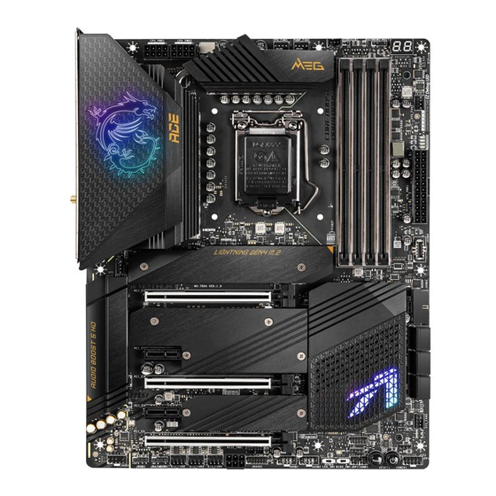
Page 29: Overview Of Components
Overview of Components JCORSAIR1 CPU Socket JRAINBOW2 PUMP_FAN1 CPU_PWR2 CPU_FAN1 CPU_PWR1 DIMMA1 DIMMA2 SYS_FAN5 DIMMB1 DIMMB2 ATX_PWR1 PCI_E1 JUSB4 SYS_FAN1 M2_1 M2_2 JLN2 JUSB3 JCI1 M2_3 JLN1 SATA ▼ 1 ▲ 2 JSMB1 SATA ▼ 3 ▲ 4 PCI_E2 SATA ▼ 5 ▲ 6 JTPM1 PCI_E3 SYS_FAN6... -
Page 30: Cpu Socket
Always unplug the power cord from the power outlet before installing or removing the CPU. ∙ Please retain the CPU protective cap after installing the processor. MSI will deal with Return Merchandise Authorization (RMA) requests if only the motherboard comes with the protective cap on the CPU socket. -
Page 31: Dimm Slots
It is recommended to use a more efficient memory cooling system for full DIMMs ∙ installation or overclocking. The stability and compatibility of installed memory module depend on installed CPU ∙ and devices when overclocking. ∙ Please refer www.msi.com for more information on compatible memory. Overview of Components Downloaded from ManualsNet.com search engine... -
Page 32: Pci_E1~4: Pcie Expansion Slots
PCI_E4: PCIe 3.0 x4 (From Z590 chipset) ⚠ Important If you install a large and heavy graphics card, you need to use a tool such as MSI ∙ Gaming Series Graphics Card Bolster to support its weight to prevent deformation of the slot. - Page 33 PCIe bandwidth configuration table for PCIe & M.2 slots The M2_2 and M2_3 slots can be used under two PCIe bandwidth modes: Chipset mode (default) and CPU mode (by BIOS setting). Please refer the PCIe bandwidth configuration table below for details. Slot Chipset mode (Default) CPU mode (By BIOS setting)
-
Page 34: M2_1~4: M.2 Slots (Key M)
M2_1~4: M.2 Slots (Key M) ⚽ Video Demonstration Watch the video to learn how to Install M.2 SSD. M2_1 https://youtu.be/2UeWMgjwogU M2_2 M2_3 M2_4 ⚠ Important Intel® RST only supports PCIe M.2 SSD with UEFI ROM. ∙ Intel® Optane™ Memory Ready for M2_2 (from chipset), M2_3 (from chipset) and ∙... - Page 35 3. Secure the supplied M.2 standoff according to your M.2 SSD length if need. 4. Insert your M.2 SSD into the M.2 slot at a 30-degree angle. 5. Secure the M.2 SSD in place with the supplied M.2 8.5H screw. ⚠...
-
Page 36: Sata1~6: Sata 6Gb/S Connectors
SATA1~6: SATA 6Gb/s Connectors These connectors are SATA 6Gb/s interface ports. Each connector can connect to one SATA device. SATA2 SATA1 SATA4 SATA3 SATA6 SATA5 ⚠ Important Please do not fold the SATA cable at a 90-degree angle. Data loss may result during ∙... -
Page 37: Jfp1, Jfp2: Front Panel Connectors
JFP1, JFP2: Front Panel Connectors These connectors connect to the switches and LEDs on the front panel. Buzzer JFP2 Speaker Speaker - Buzzer + Buzzer - Speaker + Power LED Power Switch JFP1 Reserved HDD LED Reset Switch HDD LED + Power LED + HDD LED - Power LED -... -
Page 38: Cpu_Pwr1~2, Atx_Pwr1, Pcie_Pwr1: Power Connectors
CPU_PWR1~2, ATX_PWR1, PCIE_PWR1: Power Connectors These connectors allow you to connect an ATX power supply. CPU_PWR1~2 Ground +12V Ground +12V Ground +12V Ground +12V +3.3V +3.3V +3.3V -12V Ground Ground PS-ON# Ground Ground Ground ATX_PWR1 Ground Ground PWR OK 5VSB +12V +12V +3.3V... -
Page 39: Jslow1: Slow Mode Booting Jumper
JSLOW1: Slow Mode Booting Jumper This jumper is used for LN2 cooling solution, that provides the extreme overclocking conditions, to boot at a stable processor frequency and to prevent the system from crashing. Normal Enabled (Default) (Please enable this jumper during BIOS POST.) JLN1~2: Low Temperature Booting Jumper This jumper is used for liquid nitrogen cooling system to boot at an extreme low... -
Page 40: Joc_Fs1: Safe Boot Jumper
JOC_FS1: Safe Boot Jumper This jumper is used for Safe Boot. Once enabled, the system will boot with default settings and lower PCIe (from CPU) mode. Normal Enabled (default) Apply the BIOS default Boot with the saved settings and lower PCIe BIOS settings. -
Page 41: V-Check Points Lite
V-Check Points Lite These voltage checkpoints are used to measure the current system voltages. A multimeter (not included) will be required to check voltages. To measure voltage, place test leads on the GND (screw mounting hole) and a specific V-Check Point. Please refer to the manual of your multimeter for more information. -
Page 42: Jusb4: Usb 3.2 Gen 2 Type-C Connector
JUSB4: USB 3.2 Gen 2 Type-C Connector This connector allows you to connect USB 3.2 Gen 2 Type-C connector on the front panel. The connector possesses a foolproof design. When you connect the cable, be sure to connect it with the corresponding orientation. USB Type-C Cable JUSB4 USB Type-C port on... -
Page 43: Jusb1~2: Usb 2.0 Connectors
In order to recharge your iPad,iPhone and iPod through USB ports, please install ∙ MSI® Center utility. JTPM1: TPM Module Connector This connector is for TPM (Trusted Platform Module). Please refer to the TPM security platform manual for more details and usages. -
Page 44: Cpu_Fan1, Pump_Fan1, Sys_Fan1~6: Fan Connectors
CPU_FAN1, PUMP_FAN1, SYS_FAN1~6: Fan Connectors Fan connectors can be classified as PWM (Pulse Width Modulation) Mode or DC Mode. PWM Mode fan connectors provide constant 12V output and adjust fan speed with speed control signal. DC Mode fan connectors control fan speed by changing voltage. The auto mode fan connectors can automatically detect PWM and DC mode. -
Page 45: Jci1: Chassis Intrusion Connector
JCI1: Chassis Intrusion Connector This connector allows you to connect the chassis intrusion switch cable. Normal Trigger the chassis (default) intrusion event Using chassis intrusion detector 1. Connect the JCI1 connector to the chassis intrusion switch/ sensor on the chassis. 2. -
Page 46: Jbat1: Clear Cmos (Reset Bios) Jumper
JBAT1: Clear CMOS (Reset BIOS) Jumper There is CMOS memory onboard that is external powered from a battery located on the motherboard to save system configuration data. If you want to clear the system configuration, set the jumpers to clear the CMOS memory. Keep Data Clear CMOS/ (default) -
Page 47: Jrgb1: Rgb Led Connector
Always turn off the power supply and unplug the power cord from the power outlet ∙ before installing or removing the RGB LED strip. ∙ Please use MSI’s software to control the extended LED strip. Overview of Components Downloaded from ManualsNet.com... -
Page 48: Jrainbow1~2: Addressable Rgb Led Connectors
∙ Always turn off the power supply and unplug the power cord from the power outlet before installing or removing the RGB LED strip. Please use MSI’s software to control the extended LED strip. ∙ Overview of Components Downloaded from ManualsNet.com... -
Page 49: Jcorsair1: Corsair Connector
The JCORSAIR1 connector allows you to connect the CORSAIR Individually Addressable Lighting PRO RGB LED strips 5V or CORSAIR RGB fans with the CORSAIR fan hub. Once all items are connected properly, you can control the CORSAIR RGB LED strips and fans with MSI's software. Data Ground... -
Page 50: Onboard Leds
Onboard LEDs EZ Debug LED These LEDs indicate the debug status of the motherboard. CPU - indicates CPU is not detected or fail. DRAM - indicates DRAM is not detected or fail. VGA - indicates GPU is not detected or fail. BOOT - indicates the booting device is not detected or fail. -
Page 51: Hexadecimal Character Table
Hexadecimal Character Table Hexadecimal Debug Code 0 1 2 3 4 5 6 7 8 9 A B C D E F LED display Boot Phases Security (SEC) – initial low-level initialization Pre-EFI Initialization (PEI) – memory initialization Driver Execution Environment (DXE) – main hardware initialization Boot Device Selection (BDS) –... - Page 52 Memory initialization. Configuring memory Memory initialization (other) Memory Installed CPU post-memory initialization is started CPU post-memory initialization. Cache initialization CPU post-memory initialization. Application Processor(s) (AP) initialization CPU post-memory initialization. Boot Strap Processor (BSP) selection CPU post-memory initialization. System Management Mode (SMM) initialization Post-Memory System Agent initialization is started 38 - 3A Post-Memory System Agent initialization (System Agent module specific)
- Page 53 ACPI module initialization CSM initialization Reserved for future AMI DXE codes 7A - 7F Boot Device Selection (BDS) phase is started Driver connecting is started PCI Bus initialization is started PCI Bus Hot Plug Controller Initialization PCI Bus Enumeration 32 PCI Bus Request Resources PCI Bus Assign Resources Console Output devices connect...
- Page 54 DXE Error Codes CPU initialization error System Agent initialization error PCH initialization error Some of the Architectural Protocols are not available PCI resource allocation error. Out of Resources No Space for Legacy Option ROM No Console Output Devices are found No Console Input Devices are found Invalid password Error loading Boot Option (LoadImage returned error)
-
Page 55: Acpi States Codes
FB - FF Reserved for future AMI error codes ACPI States Codes The following codes appear after booting and the operating system into ACPI modes. System is entering S1 sleep state System is entering S2 sleep state System is entering S3 sleep state System is entering S4 sleep state System is entering S5 sleep state System is waking up from the S1 sleep state... -
Page 56: Installing Os, Drivers & Msi Center
MSI Center is an application that helps you easily optimize game settings and smoothly use content creation softwares. It also allows you to control and synchronize LED light effects on PCs and other MSI products. With MSI Center, you can customize ideal modes, monitor system performance, and adjust fan speed. -
Page 57: Uefi Bios
UEFI has many new functions and advantages that traditional BIOS cannot achieve, and it will completely replace BIOS in the future. The MSI UEFI BIOS uses UEFI as the default boot mode to take full advantage of the new chipset’s capabilities. -
Page 58: Bios Setup
Select between Yes or No to confirm your choice. BIOS User Guide If you’d like to know more instructions on setting up the BIOS, please refer to http://download.msi.com/manual/mb/Intel500BIOS.pdf or scan the QR code to access. UEFI BIOS Downloaded from ManualsNet.com... -
Page 59: Resetting Bios
Updating BIOS Updating BIOS with M-FLASH Before updating: Please download the latest BIOS file that matches your motherboard model from MSI website. And then save the BIOS file into the USB flash drive. Updating BIOS: 1. Insert the USB flash drive that contains the update file into the USB port. - Page 60 1. Please download the latest BIOS file that matches your motherboard model from the MSI® website. 2. Rename the BIOS file to MSI.ROM, and save it to the root of your USB flash drive. 3. Connect the power supply to CPU_PWR1 and ATX_PWR1. (No need to install CPU and memory.)
- Page 61 目次 安全に関する注意事項 ................... 3 ケーススタンドオフの注意事項 ................4 仕様 ........................5 JCORSAIR1コネクターの仕様 ................13 パッケージの内容 ....................14 リアI/Oパネル ....................... 15 LANポートLED状態表 ................... 15 オーディオポートの配置 ..................15 Realtekオーディオコンソール ................16 アンテナの取り付け ....................18 コンポーネントの概要 ..................19 CPUソケッ ト ......................20 DIMMスロッ ト ......................21 PCI_E1~4: PCIe拡張スロッ...
- Page 62 デバッグコードLED ....................40 16進文字一覧表 ....................41 ブートフェーズ ......................41 デバッグコードLED一覧表 ..................41 ACPIステータスコード ................... 45 CPUの温度 ......................45 OS、 ドライバーおよびMSI Centerのインストール..........46 Windows® 10のインストール .................. 46 ドライバーのインス トール..................46 MSI Center ......................46 UEFI BIOS ......................47 BIOSの設定 ......................48 BIOSセッ...
-
Page 63: 安全に関する注意事項
安全に関する注意事項 ∙ 本パッケージ内のコンポーネン トは静電放電(ESD)を受けやすいので、 PCの組み立てを 確実に成功させるために以下の注意事項を守って ください。 ∙ コンポーネン トがしっかりと全部接続され手いることを確認して ください。 確実に接続さ れていない場合、 コンポーネン トの認識不良や起動不良の原因となります。 ∙ 繊細な部品に触れないよう、 マザーボードのフチを持って ください。 ∙ マザーボードを扱う際には、 静電気破壊を防ぐために、 静電放電 (ESD)リス トス トラップを 着けることをお薦めします。 ESDリストストラップが用意できない場合は、 他の金属製のもの に触れて静電気を逃してからマザーボードを扱って ください。 ∙ 本品を取り付けない時は、 静電気対策が施された箱か、 または静電気防止パッ ド上で保 管して ください。 ∙ コンピューターの電源を投入する前に、 マザーボードのショートの原因となる、 外れたネ ジや金属製の部品がマザーボード上またはPCケース内にないか、... -
Page 64: ケーススタンドオフの注意事項
ケーススタンドオフの注意事項 マザーボードをケースに取り付ける前に、 マザーボードの取り付けに必要するスタンドオフ を先にケースの取り付けプレートに取り付けて ください。 マザーボードに損害を防ぐために、 マザーボードの回路とPCケースの間に必要のない取 り付けスタンドオフを取り付けないでください。 使用者に注意するために、 「 Case standoff keep out zone」 の標示(下図のように)がマザーボードの背面に付きます。 安全に関する注意事項 Downloaded from ManualsNet.com search engine... - Page 65 ▪ 2DPC 2Rは最大4000+ MHzの速度をサポート ∙ デュアルチャンネルモードをサポート ∙ non-ECC モード 、 un-buffered メモリをサポート ∙ Intel® Extreme Memory Profile (XMP) をサポート * 互換性があるのメモリについての詳細は www.msi.com からご参照ください 。 ∙ PCIe x16スロッ ト x1 (PCI_E2、 CPU帯域接続) ▪ 第11世代CPUは最大PCIe 4.0 x16をサポート* ▪ 第10世代CPUは最大PCIe 3.0 x16をサポート* ∙ PCIe 3.0 x4スロッ ト x1 (PCI_E4、 Z590チップセッ ト帯域接...
- Page 66 * M.2 SATA SSDをM2_2スロッ トに取り付ける場合に、 SATA2は無効になります。 ** M.2 SATA / PCIe SSDをM2_2またはM2_3スロッ トに取り付ける場合に、 SATA5と SATA6は無効になります。 *** Intel® Optane™メモリレディ 。 Intel® Optane™メモリモジュールを使用する前 に、 MSIのWEBサイ トからドライバーとBIOSを最新バージョンにアップデートして く ださい。 **** PCI_E4とM2_4は同じな帯域幅を共有します。 両方も同時に使用したい場合 は、 PCI_E4はx1の速度のみ、 M2_4 はx2の速度のみをサポートします。 ただし、 グラフ ィ ックスカードをPCI_E4スロッ トに取り付けて有効にする場合、 M2_4スロッ トには何...
- Page 67 前のページから続く ∙ Intel® Z590チップセッ ト ▪ バックパネルにUSB 3.2 Gen 2x2 20Gbps Type-Cポート ▪ USB 3.2 Gen 2 10Gbpsポート x2 (バックパネルに1 Type-Aポート、 内部コネクター経由で1 Type-C利用可能) ▪ USB 3.2 Gen 1 5Gbpsポート x10 (バックパネルに8 Type-Aポート、 内部USB 3.2 Gen 1コネクター経由で2 ポー ト利用可能) ▪ バックパネルにUSB 2.0ポート x2 ∙...
- Page 68 前のページから続く ∙ 24ピンATXメイン電源コネクター x1 ∙ 8ピンATX 12V電源コネクター x2 ∙ 6ピンATX PCIE電源コネクター x1 ∙ SATA 6Gb/sコネクター x6 ∙ M.2スロッ ト x4 (M-Key) ∙ USB 3.2 Gen 2 10Gbps Type-Cポート x1 ∙ USB 3.2 Gen 1 5Gbpsコネクター x1 (2基の追加USB 3.2 Gen 1 5Gbpsポートをサポート) ∙...
- Page 69 前のページから続く ∙ クリアCMOSボタン x1 ∙ Flash BIOSボタン x1 ∙ USB 2.0 Type-Aポート x2 ∙ HDMIポート x1 ∙ USB 3.2 Gen 1 5Gbps Type-Aポート x8 バックパネルコネ ∙ LAN (RJ45) ポート x1 クター ∙ USB 3.2 Gen 2 10Gbps Type-Aポート x1 ∙ USB 3.2 Gen 2x2 20Gbps Type-Cポート x1 ∙...
- Page 70 ∙ MSI Center ∙ Intel® Extreme Tuning Utility ∙ Nahimic ソフトウェア ∙ MSI APP Player (BlueStacks) ∙ Open Broadcaster Software (OBS) ∙ CPU-Z MSI GAMING ∙ Google Chrome ™ , Google Toolbar, Google Drive ∙ Norton ™ Internet Security Solution ∙...
- Page 71 ▪ Intel WiFi ∙ 冷却 ▪ オールアルミデザイン ▪ 拡張ヒートシンクデザイン ▪ MOSFET ベースプレート ▪ M.2 Shield Frozr ▪ K7 熱パッ ド MSI独自の機能 ▪ チョークパッ ド ▪ ポンプファン ▪ スマートファンコン トロール ∙ LED ▪ Mystic Light 拡張 (RAINBOW/CORSAIR/RGB) ▪ Mystic Light SYNC ▪...
- Page 72 MSI独自の機能 ▪ デュアル CPU 電源 2x 8 pin ▪ 予備 PCIe 電源コネクター ▪ 2 オンス厚の銅を採用した PCB ∙ 体験 ▪ スマートボタン ▪ MSI Center ▪ Duet Display ▪ Frozr AI 冷却 ▪ Click BIOS 5 ▪ System Saver ▪ Flash BIOSボタン...
-
Page 73: Jcorsair1コネクターの仕様
JCORSAIR1コネクターの仕様 対応のCORSAIR RGB製品 最大のコネクター Lighting Node PRO LEDストリ ップ * LEDストリ ップの数が8以上の場合に、 20%輝度がお勧めされます。 HD120 RGBファン SP120 RGBファン LL120 RGBファン 仕様 Downloaded from ManualsNet.com search engine... -
Page 74: パッケージの内容
パッケージの内容 パッケージにすべての添付品が含まれていることをご確認ください。 マザーボード本体 MEG Z590 UNIFY ユーザーズマニュアル ドキュメンテーション クイック取り付けガイド アプリケーション ドライバー付きのUSBドライブ & ユーティ リティ SATA 6Gb/sケーブル LED JRGB Yケーブル ケーブル LED JCORSAIRケーブル LED JRAINBOWケーブル Wi-Fiアンテナ ケースのバッジ M.2ネジ + スタンドオフ (2セッ ト/パック) 付属品 MEGステッカー SATAケーブルステッカー 製品登録カード 小型ドライバーセッ ト ギフト ブラシ ⚠... -
Page 75: リアI/Oパネル
リアI/Oパネル Wi-Fi アンテナコネクター USB 3.2 Gen 1 5Gbps Type-A USB 2.0 オーディオポート 2.5 Gbps LAN クリアCMOS ボタン USB 3.2 Gen 2x2 光角型 S/ Flash 20Gbps Type-C PDIF 出力 BIOS ボタン USB 3.2 Gen 2 Flash BIOS ポート 10Gbps Type-A ∙ クリアCMOSボタン - このボタンの使用前には、 必ずPCの主電源をオフにして ください。 ク リアCMOSボタンを5-10秒押したままにすると、... -
Page 76: Realtekオーディオコンソール
Realtekオーディオコンソール Realtekオーディオコンソールをインストールした後、 優れた音声体験のために音声設定を 変更します。 アプリケーション拡張 デバイス 選択 メインボリュ ーム 接続設定 ジャ ック状態 ∙ デバイス選択 - オーディオ出力ソースを選択し、 関連のオプションを変更することができ ます。 チェックサインはそのデバイスがデフ ォルトであることを示します。 ∙ アプリケーション拡張 - 多数のオプションは、 出力デバイスと入力デバイスの両方に期待 されるサウンドエフェク トの完全なガイダンスを提供します。 ∙ メインボリューム - バーを調整することでフロン トまたはリアパネルに接続されたスピー カーの左右のバランスやボリュームをコン トロールします。 ∙ ジャック状態 - PCに現在接続されている全てのレンダーとキャプチャーデバイスを示し ます。 ∙ 接続設定 - 接続設定を行います。 オートポップアップダイアログ... - Page 77 ヘッドフォンとマイクの接続方法 ステレオスピーカーの接続方法 AUDIO INPUT 7.1チャンネルスピーカーの接続方法 AUDIO INPUT Rear Front Side Center/ Subwoofer パッケージの内容 Downloaded from ManualsNet.com search engine...
-
Page 78: アンテナの取り付け
アンテナの取り付け 1. 台座でアンテナを組合わせます。 2. 下図のように2枚のアンテナケーブルをしっかりとWiFiアンテナコネクターに固定しま す。 3. アンテナをできるだけ高く置きます。 パッケージの内容 Downloaded from ManualsNet.com search engine... -
Page 79: コンポーネントの概要
コンポーネントの概要 JCORSAIR1 CPU ソケッ ト JRAINBOW2 PUMP_FAN1 CPU_PWR2 CPU_FAN1 CPU_PWR1 DIMMA1 DIMMA2 SYS_FAN5 DIMMB1 DIMMB2 ATX_PWR1 PCI_E1 JUSB4 SYS_FAN1 M2_1 M2_2 JLN2 JUSB3 JCI1 M2_3 JLN1 SATA ▼ 1 ▲ 2 JSMB1 SATA ▼ 3 ▲ 4 PCI_E2 SATA ▼ 5 ▲ 6 JTPM1 PCI_E3 SYS_FAN6... -
Page 80: Cpuソケット
システムを起動する前に、 CPUクーラーがCPUとしっかりと密着していることを確認して ください。 CPUの過熱はCPU自身やマザーボードに深刻なダメージを与えるおそれがあります。 シス ∙ テム組み立て後初回起動時に必ずCPUファンが正常に動作していることを確認して くださ い。 CPUクーラーをマザーボードへ装着する際、 CPUとの接触面に適切な量の熱伝導性ペ ーストを塗布するか、 または熱伝導性シートを挟んでください。 CPUを外した状態でマザーボードを保管する場合は、 必ずCPUソケッ トカバーを装着し、 ∙ ソケッ トのピンを保護して ください。 CPUとは別にCPUクーラーを購入された場合は、 CPUクーラーに添付されている文書を ∙ 参照して取り付け方法の詳細を確認して下さい。 このマザーボードはオーバークロックをサポートしています。 オーバークロックを試みる ∙ 前に、 マザーボード以外のすべてのパーツがオーバークロックに耐えうるか確認して くださ い。 製品の仕様を超えるいかなる試みも推奨しません。 製品の仕様を超えた不適切な取り 扱いによ って生じた損害やリスクをMSIは保証しません。 コンポーネントの概要 Downloaded from ManualsNet.com search engine... -
Page 81: Dimmスロット
DIMMA2 DIMMA2 DIMMA2 DIMMB1 DIMMB2 DIMMB2 ⚠ 注意 ∙ メモリスロッ トはDIMMA2を最優先に使用して下さい。 ∙ デュアルチャンネルモードでのシステムの安定性を確保するためには、 同一メーカーの同 一メモリモジュールを装着する必要があります。 メモリの動作周波数はSPDに依存するため、 オーバークロックの際に公称値より低い周 ∙ 波数で動作するメモリがあります。 メモリを公称値かそれ以上の周波数で動作させたい場 合は、 BIOSメニューのDRAM Frequencyの項目で動作周波数を設定して ください。 ∙ 全てのDIMMスロッ トを使用する場合やオーバークロックをする場合はより効率的なメモ リ冷却システムの使用をお薦めします。 オーバークロック時の、 メモリの安定性と互換性は取り付けられたCPUとデバイスに依 ∙ 存します。 互換性があるのメモリについての詳細はwww.msi.comからご参照ください。 ∙ コンポーネントの概要 Downloaded from ManualsNet.com search engine... - Page 82 PCI_E3: PCIe 3.0 x1 (Z590チップセッ ト帯域接続) PCI_E4: PCIe 3.0 x4 (Z590チップセッ ト帯域接続) ⚠ 注意 大型且つ重いグラフィ ックスカードをインストールすると 、 スロッ トの変形を防止するため ∙ に 、 MSI Gaming Series Graphics Card Bolsterのようなツールを使用することが必要で す 。 一枚のPCIe x16拡張カードを最適な性能で動作させたい場合は、 PCI_E2スロッ トの使用 ∙ をお勧めします。 ∙ 拡張カードの着脱は、 必ず電源をオフにし、 コンセン トから電源ケーブルを抜いてから行っ...
- Page 83 PCIeとM.2スロットのPCIe帯域幅一覧表 M2_2とM2_3スロッ トは次の2つのPCIe帯域幅モードで有効です : チップセッ トモード(デフ ォ ルト)とCPUモード(BIOS設定)。 詳細はPCIe帯域幅一覧表をご参照ください。 スロッ チップセットモード (デフォルト) CPUモード (BIOS設定) ト PCI_E1 3.0 x1 3.0 x1 PCI_E2 4.0* x16または3.0 x16 4.0* x8または3.0 x8 PCI_E3 3.0 x1 3.0 x1 PCI_E4 — 3.0 x4 3.0 x1 — 3.0 x4 3.0 x1 4.0 x4 M2_1...
- Page 84 M2_1~4: M.2スロット (Key M) ⚽ ビデオデモンストレー ション M.2 SSDを取り付ける方法をビデ M2_1 オで確認できます。 M2_2 https://youtu.be/2UeWMgjwogU M2_3 M2_4 ⚠ 注意 Intel® RSTはUEFI ROM付きのPCIe M.2 SSDのみをサポートします。 ∙ Intel® Optane™メモリレディーはM2_2(チップセッ トから)、 M2_3(チップセッ トから)と ∙ M2_4スロッ トに対応します。 M.2モジュールの取り付け 1. M.2 SHIELD FROZRヒートシンクのねじを緩めます。 2. M.2 SHIELD FROZRヒートシンクを持ち上げ、 ヒートシンクの熱パッ ドから保護膜を取 り外します。...
- Page 85 3. 必要の場合にM.2 SSDの長さによ って供給のM.2スタンドオフを固定します。 4. 30°の角度でM.2 SSDをM.2スロッ トに挿入します。 5. 供給のM.2 8.5HねじでM.2 SSDを正しい位置に固定します。 ⚠ 注意 22110 M.2 SSDをM2_1とM2_3スロッ トに取り付ける場合、 または2280 M.2 SSDをM2_2と M2_4スロッ トに取り付ける場合、 ステップ3とステップ5を飛ばします。 8.5Hねじ 30º 30º スタンド オフ 6. M.2 SHIELD FROZRヒートシンクをヒートシンクスタンドオフに固定します。 コンポーネントの概要 Downloaded from ManualsNet.com search engine...
- Page 86 SATA1~6: SATA 6Gb/sコネクター これらのコネクターはSATA 6Gb/sインターフェースポートです。 一つのコネクターにつき、 一 つのSATAデバイスを接続できます。 SATA2 SATA1 SATA4 SATA3 SATA6 SATA5 ⚠ 注意 SATAケーブルは90度以下の角度に折り曲げないでください。 データ損失を起こす恐れが ∙ あります。 ∙ SATAケーブルは両端に同一のプラグを備えています。 然し、 スペースの確保のためにマザ ーボードにはストレートタイプのコネクタを接続されることをお薦めします。 ∙ M.2 SATA SSDをM2_2スロッ トに取り付ける場合に、 SATA2 は無効になります。 ∙ M.2 SATA / PCIe SSDをM2_2またはM2_3スロッ トに取り付ける場合に、 SATA5とSATA6 は無効になります。...
- Page 87 JFP1、 JFP2: フロントパネルコネクター これらのコネクターにはフロン トパネルのスイッチとLEDを接続します。 Buzzer JFP2 Speaker Speaker - Buzzer + Buzzer - Speaker + Power LED Power Switch JFP1 Reserved HDD LED Reset Switch HDD LED + Power LED + HDD LED - Power LED - Reset Switch Power Switch Reset Switch Power Switch...
- Page 88 CPU_PWR1~2、 ATX_PWR1、 PCIE_PWR1: 電源コネクター これらのコネクターにはATX電源を接続します。 CPU_PWR1~2 Ground +12V Ground +12V Ground +12V Ground +12V +3.3V +3.3V +3.3V -12V Ground Ground PS-ON# Ground Ground Ground ATX_PWR1 Ground Ground PWR OK 5VSB +12V +12V +3.3V Ground +12V Ground PCIE_PWR1 +12V Ground +12V Ground ⚠...
- Page 89 JSLOW1: スローモード起動ジャンパ このジャンパは極限のオーバークロック状態を提供するLN2クーリングソリューションにお いて、 安定した周波数でプロセッサを起動しシステムをクラッシュから守るために使われま す。 正常 有効 (デフ ォルト) (BIOS POSTの間にこの機能 を有効にして ください。 ) JLN1~2: 低温度起動ジャンパ このジャンパは液体窒素冷却システムにおいて使われて、 極低温で起動できるためで す。 Enabledに設定すると、 起動の成功率を上げます。 有効 正常 (デフ ォルト) (BIOS POSTの間にこの機能を有 効にして ください。 ) ⚠ 注意 ユーザーは自己のリスクのもとで極端な低温度のオーバークロックを試みます。 オーバー ∙ クロックの結果はCPUのバージョンによ って異なる場合があります。 ∙ 電源オフまたはシステムが起動不可能になろう時に、 このジャンパを“Enabled”に設定し ないでください。...
- Page 90 JOC_FS1: セーフブートジャンパ セーフブート用のジャンパです。 有効にすると、 システムはデフ ォルト設定とより低いPCIe (CPU帯域接続)モードで起動します。 正常 有効 (デフ ォルト) セーフブート時はBIOSの 保存したBIOS設定で起 デフ ォルト設定とより低い 動します。 PCIe (CPU帯域接続)モー ドを適用します。 JOC_RT1: OC Retryジャンパ このジャンパはOC項目を再試行します。 このジャンパを閉じる場合、 システムが成功に起動 をするまでOC項目を再試行し続けます。 JOC_RT1 正常 ショ ッ ト (デフ ォルト) (OCを再試行) JTBT1: Thunderbolt 追加カードコネクター このコネクターは追加の Thunderbolt I/O カードを接続します 。 TBT_Force_PWR TBT_S0IX_Entry_REQ TBT_CIO_Plug_Event#...
- Page 91 V-Checkポイント これらの電圧チェックポイン トは現在のシステムの電圧を測ります。 電圧のチェックにはマ ルチメーター(含まれない)が必要です。 電圧をチェックするには、 試験導線をGND (ねじの取 り付け穴) とV-Checkポイン トに置きます。 詳細についてはマルチメーターのマニュアルを参 照して ください。 VCCIO VCCSA DRAM VCORE VCCIO2 T_SEN1: 熱センサーコネクター このコネクターはサーミスタケーブルを接続し、 検出ポイン トの温度を監視することができ ます。 サーミスタケーブル センス JDASH1 : チューニングコントローラーコネクター このコネクタはオプションのチューニングコン トローラーモジュールを接続します。 No Pin MCU_SMB_SCL_M MCU_SMB_SDA_M VCC5 Ground PSIN#_R FP_RST#_R OC_RETRY# OC_FS BLK+...
- Page 92 JUSB4: USB 3.2 Gen 2 Type-Cコネクター このコネクターにはフロン トパネルのUSB 3.2 Gen 2 Type-Cコネクターを接続します。 この コネクターは確実なデザインを持っています。 ケーブルを接続すると、 対応方向で接続する ことを確認して ください。 USB Type-Cケー JUSB4 ブル フロン トパネルの USB Type-Cポート JUSB3: USB 3.2 Gen 1コネクター このコネクターにはフロン トパネルのUSB 3.2 Gen 1 5Gbpsポートを接続します。 Power USB2.0+ USB3_RX_DN USB2.0- USB3_RX_DP Ground...
- Page 93 Ground Ground No Pin ⚠ 注意 ∙ VCCピンとグランドピンは必ず接続して ください。 正し く接続されていない場合、 機器が損 傷するおそれがあります。 これらのUSBポートでiPad、 iPhoneとiPodを再充電するには、 MSI® Center ユーティ リテ ∙ ィをインストールして ください。 JTPM1: TPMモジュールコネクター このコネクターはTPM (Trusted Platform Module)を接続します。 詳細についてはTPMセキ ュリティ プラッ トホームマニュアルを参照して下さい。 SPI Power SPI Chip Select Master In Slave Out (SPI Data)
- Page 94 CPU_FAN1、 PUMP_FAN1、 SYS_FAN1~6: ファンコネクター ファンコネクターはPWM (パルス幅変調)モードとDCモードに分類されます。 PWMモードフ ァンコネクターには常時12Vが出力されており、 スピードコン トロール信号によ ってファンス ピードを調整します。 DCモードファンコネクターは電圧出力を変えることでファンスピード をコン トロールします。 自動モードファンコネクターは自動的にPWMまたはDCモードを検 出することができます。 下記の説明に従って手動でファンコネクターをPWMまたはDCモー ドに調整できます。 CPU_FAN1 PUMP_FAN1 SYS_FAN5 デフォルト 最大電 コネクター ファンモ 最大電流 源 ード SYS_FAN1 CPU_FAN1 自動モード PUMP_FAN1 PWMモード SYS_FAN1~6 自動モード SYS_FAN6 SYS_FAN2 SYS_FAN3 SYS_FAN4 ファンモードの切り替えとファンスピードの調整...
- Page 95 JCI1: ケース開放スイッチコネクター このコネクターにはケース開放スイッチケーブルを接続します。 正常 ケース開放イベン ト ト (デフ ォルト) リガー有効 ケース開放検知機能の使い方 1. JCI1コネクターをケース開放スイッチ/センサーに接続します。 2. ケースのカバーを閉じます。 3. BIOS > SETTINGS > Security > Chassis Intrusion Configurationに入ります。 4. Chassis IntrusionをEnabledに設定します。 5. F10を押すと、 設定を保存して終了するかメッセージが出ますので、 Enterキーを押して Yesを選択します。 6. ケースが開けられるとシステムに開放の情報が記録され、 次回のシステム起動時に警 告メッセージが表示されます。 ケース開放警告のリセット 1. BIOS > SETTINGS > Security > Chassis Intrusion Configurationに入ります。 2.
- Page 96 JBAT1: クリアCMOS (BIOSリセット) ジャンパ 本製品はシステムの設定情報を保持するCMOSメモリを搭載しており、 マザーボード上のボ タン型電池から電力が供給されます。 システムの設定をクリアしたい場合は、 CMOSメモリ をクリアするためにジャンパピンにジャンパブロックを取り付けて ください。 データを CMOSをクリア/ 保持 BIOSをリセッ ト (デフ ォルト) BIOSをデフォルト値にリセットする 1. PCの電源をオフにし、 コンセン トから電源コードを抜いて下さい。 2. ジャンパブロックでJBAT1を5-10秒ぐ らいショ ッ トします。 3. JBAT1からジャンパブロックを取り外します。 4. 電源コードをコンセン トに元通りに接続し、 電源を投入します。 BIOS_SW1: マルチBIOSスイッチ 本製品は内蔵のBIOS ROMを二つ搭載しておきます。 一つがクラッシュされると、 このスイッ チを滑り、...
- Page 97 JRGBコネ クター RGB LEDファンコネクター JRGBコネクター RGB LEDファン システムファンコネクター ⚠ 注意 RGB コネクターは長さ2m以下のものを御使用ください。 定格最大出力は3A (12V) ∙ で、 5050 RGB LEDストリ ップ(12V/G/R/B)をサポートします。 RGB LEDストリ ップの着脱は、 必ず電源ユニッ トのスイッチをオフにして電源コードを抜 ∙ いた状態で実施して ください。 ∙ MSIのソフ トウェアで拡張 LEDストリ ップをコン トロールします。 コンポーネントの概要 Downloaded from ManualsNet.com search engine...
- Page 98 ネクターは異なる電圧を供給し、 5V LEDストリ ップをJRGBコネクターに接続すると、 LEDス トリ ップが損傷します。 ⚠ 注意 RAINBOWコネクターの定格最大出力は3A (5V)で、 75 LEDs WS2812B個々にアドレス可 ∙ 能なRGB LEDストリ ップ (5V/Data/Ground)をサポートします。 20%の輝度の場合には、 コネ クターは最大200 LEDをサポートします。 ∙ RGB LEDストリ ップの着脱は、 必ず電源ユニッ トのスイッチをオフにして電源コードを抜 いた状態で実施して ください。 MSIのソフ トウェアで拡張 LEDストリ ップをコン トロールします。 ∙ コンポーネントの概要 Downloaded from ManualsNet.com search engine...
- Page 99 JCORSAIR1: CORSAIRコネクター JCORSAIR1コネクターはCORSAIRファンハブでCORSAIR個々にアドレス可能なLighting PRO RGB LEDストリ ップ5VまたはCORSAIR RGBファンを接続することができます。 全ての 項目が正し く接続されると、 MSIのソフ トウェアでCORSAIR RGB LEDス トリ ップとファンをコ ン トロールできます 。 Data Ground CORSAIR RGBファンコネクター SATA電源 CORSAIR RGB LEDファン SYS_FAN SYS_FAN SYS_FAN SYS_FAN SYS_FAN SYS_FAN JCORSAIR1コネクター CORSAIR Lighting Node PROの接続 ⚠...
- Page 100 オンボードLED EZ Debug LED これらのLEDはメモリモジュールが取り付けられたことを表示します。 CPU - CPUが検出されないか、 または認識に失敗したこ とを示します。 DRAM - DRAMが検出されないか、 または認識に失敗し たことを示します。 VGA - GPUが検出されないか、 または認識に失敗したこ とを示します。 BOOT - ブートデバイスが検出されないか、 または認識 に失敗したことを示します。 XMP LED このLEDはXMP (Extreme Memory Profile)モードが有効にすることを表示します。 XMP LED デバッグコードLED デバッグコードLEDにはPOST中 ・ POST後のCPUコア温度(デフ ォルト)、 進行状況とエラーコ ードが表示されます。 詳細についてはデバッグコードLED一覧表をご参照ください。 デバッグコードLED オンボードLED Downloaded from...
- Page 101 16進文字一覧表 16進数 デバッグコー 0 1 2 3 4 5 6 7 8 9 A B C D E F ドLED表示 ブートフェーズ Security (SEC) – 初期のローレベル初期化 Pre-EFI Initialization (PEI) – メモリ初期化 Driver Execution Environment (DXE) – メインハードウェア初期化 Boot Device Selection (BDS) – システムセッ トアップ、 pre-OSユーザーインターフェースお よび起動可能なデバイスの選択...
- Page 102 メモリ初期化 : メモリ設定 メモリ初期化 : その他 メモリが装着された CPU post-memory初期化開始 CPU post-memory初期化 : キャ ッシュ初期化 CPU post-memory初期化 : アプリケーションプロセッサー(AP)初期化 CPU post-memory初期化 : ブートストラッププロセッサー(BSP)選択 CPU post-memory初期化 : システムマネジメン トモード(SMM)初期化 Post-Memoryシステムエージェン ト初期化開始 38 - 3A Post-Memoryシステムエージェン ト初期化 (システムエージェン トモジュール固有) Post-Memory PCH初期化開始 3C - 3E Post-Memory PCH初期化...
- Page 103 ACPIモジュール初期化 CSM初期化 未定義 (DXEコード用に予約済み) 7A - 7F ブートデバイス選択フェーズ開始 ドライバー接続開始 PCIバス初期化開始 PCIバスホッ トプラグコン トローラー初期化 PCIバス Enumeration 32 PCIバス リソース要求 PCIバス リソース割り当て コンソール出力デバイスの接続 コンソール入力デバイスの接続 スーパーIO初期化 USB初期化開始 USBリセッ ト USB検出 USB有効 9E -9F 未定義 (予約済み) IDE初期化開始 IDEリセッ ト IDE検出 IDE有効 SCSI初期化開始 SCSIリセッ ト SCSI検出...
- Page 104 DXEエラーコード CPU初期化エラー システムエージェン ト初期化エラー PCH初期化エラー 有効でないアーキテクチャプロトコルがある PCIリソース割り当てエラー。 リソースが不足している レガシーOption ROM用のスペースがない コンソール出力デバイスが見つからない コンソール入力デバイスが見つからない 無効パスワード ブートオプションロード中のエラー (LoadImageがエラーを返した) ブートオプション失敗 (StartImageがエラーを返した) フラッシュアップデート失敗 リセッ トプロトコルが有効でない S3レジューム進行コード S3レジューム開始 (S3 Resume PPIがDXE IPLによ ってコールされた) S3ブートスクリプト実行 ビデオリポスト OS S3 wakeベク トルコール E4 - E7 未定義 (予約済み) S3ジュームエラーコード S3レジューム失敗 S3レジュームPPIが見つからなかった...
- Page 105 ACPIステータスコード 下記のコードはOSがACPIモードに入っている際に表示されます。 システムがS1スリープ状態です システムがS2スリープ状態です システムがS3スリープ状態です システムがS4スリープ状態です システムがS5スリープ状態です システムがS1スリープ状態から復帰中です システムがS2スリープ状態から復帰中です システムがS3スリープ状態から復帰中です システムがS4スリープ状態から復帰中です システムはACPIモードに移行中です。 割り込みコン トローラーはPICモードです。 システムはACPIモードに移行中です。 割り込みコン トローラーはAPICモードです。 CPUの温度 00 - 99 OS起動後は現在のCPUの温度が表示されます。 オンボードLED Downloaded from ManualsNet.com search engine...
- Page 106 7. OK ボタンを押して 、 インス トールを完了させます 。 8. PC を再起動させます 。 MSI Center MSI Center はゲーム設定の最適化とコンテンツ作成ソフ トの使用に役立つアプリケーシ ョンです 。 また 、 PC や他の MSI 製品の LED ライ トの効果を操作し 、 同期することができます 。 MSI Center により 、 モードをカスタマイズしたり 、 システムを管理やファンの回転速度を調整 したりできます 。 MSI Centerユーザーズガイド...
- Page 107 UEFI BIOS MSI UEFI BIOSはUEFI (Unified Extensible Firmware Interface)アーキテクチャと互換性 があります。 UEFIは、 従来のBIOSでは実現できない新機能と利点を多く持っています、 将来 は完全にBIOSに取って代わることができます。 MSI UEFI BIOSは、 デフ ォルトのブートモード としてUEFIを使用し、 新しいチップセッ トの機能を最大限に活用することができます。 ⚠ 注意 ほかの説明がない限り、 本ユーザマニュアルの用語のBIOSはUEFI BIOSを指します。 UEFIの利点 ∙ クイック起動 - UEFIは直接にオペレーティ ングシステムを起動し、 BIOSセルフテス トプロ セスを保存することができます。 また、 POST時にCSMモードに切り替えにかかる時間も排 除します。 ∙ 2 TBより大きいハードディ スクドライブパーティションをサポートします。...
- Page 108 Memory-Zメニューに入る optimized defaultsをロードする アドバンストモードとEZモードの間に切り替える OCプロファイルをロードする OCプロファイルをセーブする F10: 設定を保存して再起動させる* F12: スクリーンショ ッ トが撮られ 、 USBメモリに保存されます (FAT/ FAT32フ ォーマッ トの み) Ctrl+F: 検索ページに入る * <F10>キーを押すと確認ウィ ンドウが表示され、 修正情報が表示されます。 Yesまたは Noを選択して確認して ください。 BIOSユーザーズガイド BIOSの設定の他の説明は、 http://download.msi.com/manual/mb/Intel500BIOSjp.pdf またはQRコードからアクセスして ください。 UEFI BIOS Downloaded from ManualsNet.com search engine...
- Page 109 ∙ マザーボード上のクリアCMOSジャンパをショートする。 ∙ リアI/OパネルのクリアCMOSボタンを押す。 ⚠ 注意 CMOSデータをクリアする前に、 必ずPCの電源がオフにすることを確認して ください。 BIOS のリセッ トについてはクリアCOMSジャンパセクションをご参照ください。 BIOSのアップデート方法 M-FLASHでのBIOSアップデート アップデートの前に: MSIのWEBサイ トから最新のBIOSファイルをダウンロードし、 USBメモリのルートフ ォルダに コピーします。 BIOSのアップデート: 1. アップデートするBIOSイメージファイルを含むUSBメモリをマザーボードのUSBポート に挿入します。 2. 下記の方法でフラッシュモードに入ります。 ▪ POST中に<Ctrl + F5>キーを押して、 Yesをクリ ックしてシステムを再起動させます。 <Ctrl+F5>キーを押して、 M-Flashをアクティ ブさせてBIOSのアップ デートを行います。 ▪ POST中に<Delete>キーを押してBIOSセッ トアップ画面に入ります。 M-FLASHタブを...
- Page 110 MSI CenterでのBIOSアップデート アップデートの前に: ∙ LANドライバーがインストールされ、 インターネッ ト接続が正し く設定されていることを確 認して ください。 ∙ アップデートする前に、 他のアプリケーションソフ トをすべて閉じて ください。 BIOSのアップデート: 1. MSI CENTERをインストールして起動させて、 Supportページに入ります。 2. Live Updateを選択して、 Advancedボタンをクリ ックします。 3. BIOSファイルを選択して、 Installボタンをクリ ックします。 4. インストールのリマインダーが表示されると、 Installボタンをクリ ックします。 システムが自動的に再起動してBIOSのアップデートを始めます。 6. アップデートプロセスが完了した後、 システムが自動的に再起動します。 Flash BIOSボタンでのBIOSアップデート 1. MSIのWEBサイ トから最新のBIOSファイルをダウンロードします。...
- Page 111 목차 안전 지침 ......................... 3 케이스 스탠드 오프 공지.................... 4 사양 ......................... 5 JCORSAIR1 커넥터 사양 ..................13 제품 내용물......................14 후면 I/O 패널 ......................15 LAN 포트 LED 상태 표시 ..................15 오디오 포트 구성 도표 ..................... 15 Realtek 오디오 콘솔 ....................16 안테나...
- Page 112 CPU 온도 ....................... 45 OS, 드라이브 & 유틸리티 설치하기 ................ 46 Windows® 10 설치하기 ................... 46 드라이버 설치하기 ....................46 MSI 센터 ........................ 46 UEFI BIOS ......................47 BIOS (바이오스) 설정 ....................48 BIOS 설정....................... 48 BIOS 사용자 가이드 ....................48 BIOS 리셋.......................
-
Page 113: 안전 지침
안전 지침 ∙ 이 패키지에 포함된 부품은 정전기 방전(ESD)에 의해 파손될 우려가 있으므로 다음의 설명에 따라 컴퓨터를 조립하십시오. ∙ 모든 부품이 제대로 연결되었는지 확인하십시오. 제대로 연결되지 않을 경우, 컴퓨터가 부품을 인식하지 못하거나 컴퓨터를 켤 수가 없게 됩니다. ∙ 부품의 예리한 부분에 손을 다칠 수 있으므로 메인보드 취급시 가장자리 부분을 잡으십시오. ∙... -
Page 114: 케이스 스탠드 오프 공지
케이스 스탠드 오프 공지 메인보드를 케이스에 설치하기 전에 먼저 케이스의 마운팅 플레이트에 메인보드에 필요한 장착 스탠드오프를 설치합니다. 메인보드의 손상을 방지하기 위해 메인보드 회로와 컴퓨터 케이스 사이에 불필요한 장착 스탠드오프는 금지됩니다. 케이스 스탠드오프 유지 구역 표지판은 메인보드 뒷면(아래 그림 참조)에 표시되어 사용자에게 경고의 역할을 합니다. 목차... - Page 115 ∙ 듀얼 채널 모드 지원 ∙ non-ECC, un-buffered 메모리 지원 ∙ 인텔 ® 익스트림 메모리 프로필 (XMP) 지원 * 호환 가능한 메모리에 대한 최신 정보는 http://www.msi.com을 방문하여 알아보시기 바랍니다. ∙ 1x PCIe x16 슬롯 (PCI_E2, CPU) ▪ 최대 PCIe 4.0 x16 (11세대 인텔® CPU용) 지원* ▪...
- Page 116 ** M2_2 또는 M2_3 슬롯에 M.2 SATA / PCIe SSD가 설치되어 있다면 SATA 5 및 SATA 6은 사용할 수 없습니다. *** 인텔® Optane™ 메모리 모듈을 사용하기 전에 MSI 웹 사이트에서 최신 버전의 드라이버와 BIOS를 업데이트했는지 확인하세요. **** PCI_E4와 M2_4는 동일한 대역폭을 공유합니다. 두 가지를 동시에 사용하려는...
- Page 117 이전 페이지로부터 계속 ∙ 인텔 ® Z590 칩셋 ▪ 1x USB 3.2 Gen 2x2 20Gbps 후면 패널에 C타입 포트 ▪ 2x USB 3.2 Gen 2 10Gbps 포트 (후면 패널에 A타입 1포트 및 C타입 내장 커넥터 1포트) ▪ 10x USB 3.2 Gen 1 5Gbps 포트 (후면 패널에 A타입 8포트, 내장...
- Page 118 이전 페이지로부터 계속 ∙ 1x 24 핀 ATX 메인 전원 커넥터 ∙ 2x 8 핀 ATX 12V 전원 커넥터 ∙ 1x 6 핀 ATX PCIE 전원 커넥터 ∙ 6x SATA 6Gb/s 커넥터 ∙ 4x M.2 슬롯 (M-Key) ∙ 1x USB 3.2 Gen 2 10Gbps C타입 포트 ∙...
- Page 119 이전 페이지로부터 계속 ∙ 1x CMOS 클리어 버튼 ∙ 1x 플래쉬 BIOS 버튼 ∙ 2x USB 2.0 A타입 포트 ∙ 1x HDMI 포트 ∙ 8 x USB 3.2 Gen 1 5Gbps A타입 포트 후면 패널 커넥터 ∙ 1 x LAN (RJ45) 포트 ∙...
- Page 120 이전 페이지로부터 계속 ∙ 드라이버 ∙ MSI 센터 ∙ 인텔® 익스트림 튜닝 유틸리티 ∙ 나히믹 ∙ MSI APP 플레이 (Bluestack) 소프트웨어 ∙ Open Broadcaster Software (OBS) ∙ CPU-Z MSI 게이밍 ∙ 구글 유틸리티 : 크롬™, 툴바, 드라이브 ∙ 노턴™ 인터넷 시큐리티 솔루션...
- Page 121 이전 페이지로부터 계속 ∙ 오디오 ▪ 오디오 부스트 5 ▪ 나히믹 3 ▪ 사운드 튠 ∙ 네트워크 ▪ 2.5G LAN ▪ LAN 매니저 ▪ 인텔 WiFi ∙ 쿨링 ▪ 모든 알루미늄 디자인 ▪ 확장된 히트싱크 디자인 ▪ MOSFET 백플레이트 ▪ M.2 쉴드 프로져 특수...
- Page 122 ▪ 듀얼 CPU 전원 2x 8 핀 ▪ 보조 PCIE 전원 커넥터 ▪ 2oz Copper thickened PCB ∙ 익스피리언스 ▪ 스마트 버튼 ▪ MSI 센터 ▪ 듀엣 디스플레이 ▪ 프로져 AI 쿨링 ▪ 클릭 BIOS 5 ▪ 시스템 세이버 ▪ 플래쉬 BIOS 버튼...
-
Page 123: Jcorsair1 커넥터 사양
JCORSAIR1 커넥터 사양 CORSAIR RGB 제품 지원 최대 연결 라이팅 노드 PRO LED 스트립 * LED 스트립 수가 8을 초과할 경우 20%의 밝기를 권장합니다. HD120 RGB 팬 SP120 RGB 팬 LL120 RGB 팬 사양 Downloaded from ManualsNet.com search engine... -
Page 124: 제품 내용물
제품 내용물 메인보드 패키지의 내용물을 확인하십시오.다음 품목들이 패키지에 들어 있어야 합니다: 메인보드 MEG Z590 UNIFY 사용 설명서 서류 빠른 설치 설명서 애플리케이션 드라이버 & 유틸리티를 포함한 USB 드라이브 SATA 6Gb/s 케이블 LED JRGB Y 케이블 케이블 LED JCORSAIR 케이블 LED JRAINBOW 케이블... -
Page 125: 후면 I/O 패널
후면 I/O 패널 Wi-Fi 안테나 USB 3.2 Gen 1 커넥터 5Gbps A 타입 USB 2.0 오디오 포트 2.5 Gbps LAN CMOS 클리어 버튼 USB 3.2 Gen 2x2 옵티컬 플래쉬 20Gbps C 타입 S/PDIF-출력 BIOS 버튼 USB 3.2 Gen 2 플래쉬 BIOS 포트 10Gbps A 타입... -
Page 126: Realtek 오디오 콘솔
Realtek 오디오 콘솔 Realtek 오디오 콘솔을 설치한 후 사운드 설정을 변경하여 더 나은 사운드를 경험할 수 있습니다. 애플리케이션 강화 장치 선택 메인 볼륨 커넥터 설정 잭 설정 ∙ 장치 선택 - 오디오 출력 소스를 선택하여 관련 옵션을 변경합니다. 체크 표시된 장치가 기본 장치입니다. - Page 127 헤드폰 및 마이크용 오디오 잭 도표 스테레오 스피커용 오디오 잭 도표 AUDIO INPUT 7.1-채널 스피커용 오디오 잭 도표 AUDIO INPUT Rear Front Side Center/ Subwoofer 제품 내용물 Downloaded from ManualsNet.com search engine...
-
Page 128: 안테나 설치하기
안테나 설치하기 1. 안테나를 받침대와 결합합니다. 2. 아래와 같이 2 개의 안테나 케이블을 WiFi 안테나 커넥터에 나사로 단단히 고정합니다. 3. 안테나를 가능한 한 높은곳에 배치합니다. 제품 내용물 Downloaded from ManualsNet.com search engine... -
Page 129: 구성품 개요
구성품 개요 JCORSAIR1 CPU 소켓 JRAINBOW2 PUMP_FAN1 CPU_PWR2 CPU_FAN1 CPU_PWR1 DIMMA1 DIMMA2 SYS_FAN5 DIMMB1 DIMMB2 ATX_PWR1 PCI_E1 JUSB4 SYS_FAN1 M2_1 M2_2 JLN2 JUSB3 JCI1 M2_3 JLN1 SATA ▼ 1 ▲ 2 JSMB1 SATA ▼ 3 ▲ 4 PCI_E2 SATA ▼ 5 ▲ 6 JTPM1 PCI_E3 SYS_FAN6... -
Page 130: Cpu 소켓
CPU를 설치하거나 제거하기 전에 전원 코드를 콘센트에서 뽑아주시기 바랍니다. 프로세서를 설치한 후, CPU 보호 캡을 보관하시기 바랍니다. 반품시 메인보드와 CPU 소켓 ∙ 보호 캡이 함께 제공되어야만 MSI에서 반품(RMA) 요청 처리를 진행할 수 있습니다. ∙ CPU 설치시, CPU 히트싱크를 반드시 설치하세요. CPU 히트싱크는 과열을 방지하고 시스템... -
Page 131: Dimm 슬롯
풀 DIMM 설치 또는 오버클로킹을 위해 보다 효율적으로 메모리 냉각 시스템을 사용할 것을 ∙ 권장합니다. 오버클로킹시의 안정성과 설치된 메모리 모듈의 호환성은 설치된 CPU 및 장치에 따라 ∙ 달라집니다. ∙ 호환 가능한 메모리에 대한 자세한 정보는 www.msi.com을 방문하여 알아보시기 바랍니다. 구성품 개요 Downloaded from ManualsNet.com search engine... -
Page 132: Pci_E1~4: Pcie 확장 슬롯
⚠ 중요사항 크고 무거운 그래픽 카드를 설치할 경우, 그래픽 카드를 안전하게 지지하여 슬롯의 변형을 ∙ 방지하기 위해 MSI 게이밍 시리즈 그래픽 카드 지지대와 같은 장치를 사용하시면 더욱 안전합니다. 하나의 PCIe x16 확장 카드를 설치하여 최적의 효과를 원하신다면 PCI_E2슬롯을 사용할 ∙... - Page 133 PCIe & M.2 슬롯을 위한 PCIe 대역 구성표 M2_2 및 M2_3 슬롯은 칩셋 모드 (기본값) 및 CPU 모드 (BIOS 설정 기준)의 두 가지 PCIe 대역폭 모드에서 사용할 수 있습니다. 자세한 내용은 아래 PCIe 대역폭 구성표를 참조하십시오. 슬롯 칩셋 모드 (기본값) CPU 모드...
-
Page 134: M2_1~4: M.2 슬롯 (Key M)
M2_1~4: M.2 슬롯 (Key M) ⚽ 데모 동영상 M.2 SSD 설치 방법을 알아보려면 아래의 웹사이트를 방문하세요 . M2_1 https://youtu.be/2UeWMgjwogU M2_2 M2_3 M2_4 ⚠ 중요사항 인텔® RST는 PCIe M.2 SSD UEFI ROM만 지원합니다. ∙ 인텔® Optane™ Memory Ready (M2_2 (칩셋), M2_3 (칩셋) 및 M2_4 슬롯용. ∙... - Page 135 3. 필요한 경우 M.2 SSD 길이에 따라 스탠드오프의 위치를 이동합니다. 4. M.2 SSD를 30도 각도로 M.2 슬롯에 삽입합니다. 5. 제공된 M.2 8.5H 나사로 M.2 SSD를 제자리에 고정합니다. ⚠ 중요사항 M2_1 및 M2_3 슬롯에 22110 M.2 SSD를 설치하거나 M2_2 및 M2_4 슬롯에 2280 M.2 SSD 를...
-
Page 136: Sata1~6: Sata 6Gb/S 커넥터
SATA1~6: SATA 6Gb/s 커넥터 이 커넥터는 SATA 6Gb/s 인터페이스 포트입니다 . 각 커넥터에 하나의 SATA 장치를 연결할 수 있습니다 . SATA2 SATA1 SATA4 SATA3 SATA6 SATA5 ⚠ 중요사항 ∙ SATA 케이블을 90 도로 꺽지 마십시오 . 그럴 경우 , 전송 중 데이터가 손상될 수 있습니다 . SATA 케이블의... -
Page 137: Jfp1, Jfp2: 전면 패널 커넥터
JFP1, JFP2: 전면 패널 커넥터 이 커넥터를 사용하여 전면 패널에 있는 스위치 및 LED 를 연결할 수 있습니다 . Buzzer JFP2 Speaker Speaker - Buzzer + Buzzer - Speaker + 전원 LED 전원 스위치 JFP1 Reserved HDD LED 리셋 스위치 HDD LED + Power LED + HDD LED -... -
Page 138: Cpu_Pwr1~2, Atx_Pwr1, Pcie_Pwr1: 전원 커넥터
CPU_PWR1~2, ATX_PWR1, PCIE_PWR1: 전원 커넥터 이 커넥터를 사용하여 ATX 전원 공급 장치를 연결할 수 있습니다 . CPU_PWR1~2 Ground +12V Ground +12V Ground +12V Ground +12V +3.3V +3.3V +3.3V -12V Ground Ground PS-ON# Ground Ground Ground ATX_PWR1 Ground Ground PWR OK 5VSB +12V +12V... -
Page 139: Jslow1: 슬로우 모드 부팅 점퍼
JSLOW1: 슬로우 모드 부팅 점퍼 이 점퍼는 LN2 쿨링을 위한 솔루션으로서 익스트림 오버클럭 상태의 프로세서를 안정된 클럭으로 유지하게 해주며 시스템 충돌을 막을 수 있습니다. 표준 상태 활성화 (기본 설정) (BIOS POST 동안, 이 기능을 “사용”으로 설정) JLN1~2: 저온 부팅 점퍼 이... -
Page 140: Joc_Fs1: 안전 부팅 점퍼
JOC_FS1: 안전 부팅 점퍼 이 점퍼는 안전 부팅에 사용됩니다. 활성화되면 시스템이 기본 설정 및 낮은 PCIe (CPU) 모드로 부팅됩니다. 표준 상태 활성화 (기본 설정) 안전 부팅을 위해 BIOS 기본 설정 및 낮은 PCIe 안전 BIOS 설정으로 부팅 (CPU) 모드를 적용 JOC_RT1: OC 재시도... -
Page 141: V-체크 포인트 라이트
V-체크 포인트 라이트 본 전압 체크 포인트는 현재 시스템 전압을 측정하는데 사용됩니다. 전압을 확인하려면 멀티미터(제품 내 미포함)가 필요합니다. 전압을 측정하기 위해서는, GND (접지 그라운드) 와 V-체크포인트에 테스트 리드를 올려 두십시오. 더 자세한 정보는 멀티미터의 매뉴얼을 참조하세요. VCCIO VCCSA DRAM VCORE VCCIO2 T_SEN1: 열... -
Page 142: Jusb4: Usb 3.2 Gen 2 C타입 커넥터
JUSB4: USB 3.2 Gen 2 C타입 커넥터 이 커넥터를 사용하여 전면 패널의 USB 3.2 Gen 2 C타입 커넥터를 연결할 수 있습니다. 이 커넥터는 풀 프루프(foolproof )로 작동하도록 디자인되었으며 케이블 연결시 정확한 방향으로 연결하시기 바랍니다. USB C타입 케이블 JUSB4 전면 패널 USB C타입 포트... -
Page 143: Jusb1~2: Usb 2.0 커넥터
∙ VCC 및 그라운드 핀을 정확히 연결하여야 손상을 방지할 수 있습니다 . ∙ USB 포트를 통하여 iPad,iPhone 및 iPod 를 충전하려면 MSI® 센터 유틸리티를 설치하시기 바랍니다 . JTPM1: TPM 모듈 커넥터 이 커넥터는 TPM (Trusted Platform Module) 모듈에 연결됩니다 . 자세한 내용과 사용방법은... -
Page 144: Cpu_Fan1, Pump_Fan1, Sys_Fan1~6: 팬 커넥터
CPU_FAN1, PUMP_FAN1, SYS_FAN1~6: 팬 커넥터 팬 커넥터는 PWM (Pulse Width Modulation) 모드와 DC 모드로 분류될 수 있습니다. PWM 모드 팬 커넥터는 12V의 일정한 출력을 제공하고 속도 제어 신호에 따라 팬의 회전 속도를 조정합니다. DC 모드 팬 커넥터는 전압의 변화에 따라 팬의 회전 속도를 제어합니다. 자동 모드... -
Page 145: Jci1: 섀시 침입 커넥터
JCI1: 섀시 침입 커넥터 이 커넥터를 사용하여 섀시 침입 스위치 케이블을 연결할 수 있습니다. 표준 상태 섀시 침입 (기본 설정) 이벤트 트리거 섀시 침입 탐지기 사용하기 1. JCI1 섀시의 섀시 침입 스위치 / 센서에 연결합니다 . 2. 섀시 커버를 닫습니다 . 3. -
Page 146: Jbat1: Cmos (Reset Bios) 클리어 점퍼
JBAT1: CMOS (Reset BIOS) 클리어 점퍼 보드에 시스템 구성 데이터를 유지하기 위해 외부 배터리로부터 전원을 공급 받는 CMOS 메모리가 있습니다. 시스템 구성을 지우려면 점퍼를 아래와 같이 설정하여 CMOS 메모리를 지우세요. 데이터 유지 CMOS 클리어/ (기본 설정) BIOS 리셋 기본 값으로 BIOS 리셋하기 1. -
Page 147: Jrgb1: Rgb Led 커넥터
JRGB 커넥터는 최대 3A (12V) 정격 전력에서 최대 2미터 연속 5050 RGB LED 스트립 ∙ (12V/G/R/B)을 지원합니다. RGB LED 스트립을 설치 또는 제거하기 전에 항상 전원 공급 장치의 전원을 끄고 전원 ∙ 코드를 콘센트에서 뽑아주세요. ∙ MSI 소프트웨어를 사용하여 확장된 LED 스트립을 조정하세요. 구성품 개요 Downloaded from ManualsNet.com search engine... -
Page 148: Jrainbow1~2: 주소 지정 가능한 Rgb Led 커넥터
RGB LED 스트립(5V/Data/Ground)을 지원합니다. 밝기 20%의 경우에 커넥터는 최대 200 개의 LED를 지원합니다. ∙ RGB LED 스트립을 설치 또는 제거하기 전에 항상 전원 공급 장치의 전원을 끄고 전원 코드를 콘센트에서 뽑아주세요. ∙ MSI 소프트웨어를 사용하여 확장된 LED 스트립을 조정하세요. 구성품 개요 Downloaded from ManualsNet.com search engine... -
Page 149: Jcorsair1: Corsair 커넥터
JCORSAIR1: CORSAIR 커넥터 JCORSAIR1 커넥터는 CORSAIR 개별 주소 지정가능한 라이팅 PRO RGB LED 스트립 5V 또는 CORSAIR RGB 팬을 CORSAIR 팬 허브와 연결할 수 있습니다. 모든 항목이 제대로 연결되면 CORSAIR RGB LED 스트립과 팬을 MSI 소프트웨어와 함께 조정할 수 있습니다. Data Ground CORSAIR RGB 팬... -
Page 150: 온보드 Leds
온보드 LEDs EZ 디버그 LED 이 LED는 메인보드의 디버그 상태를 나타냅니다. CPU -CPU가 감지되지 않거나 고장났음을 나타냅니다. DRAM -DRAM이 감지되지 않거나 고장났음을 나타냅니다. VGA - GPU가 감지되지 않거나 고장났음을 나타냅니다. BOOT - 부팅 장치가 감지되지 않거나 고장났음을 나타냅니다. XMP LED LED는... -
Page 151: 16진수 도표
16진수 도표 16진수 디버그 코드 LED 0 1 2 3 4 5 6 7 8 9 A B C D E F 디스플레이 부팅 페이즈 보안 (SEC) – 초기 낮은 레벨의 초기화 Pre-EFI Initialization (PEI) – 메모리 초기화 Driver Execution Environment (DXE) – 주요 하드웨어 초기화 Boot Device Selection (BDS) –... - Page 152 메모리 초기화. 메모리 구성 메모리 초기화 (기타) 메모리 설치됨 CPU post-memory 초기화 작동 CPU post-memory 초기화. 캐시 초기화 CPU post-memory 초기화. Application Processor(s) (AP) 초기화 CPU post-memory 초기화. Boot Strap Processor (BSP) 선택 CPU post-memory 초기화. System Management Mode (SMM) 초기화 Post-Memory System Agent 초기화...
- Page 153 ACPI 모듈 초기화 CSM 초기화 AMI DXE 코드를 위한 예비용 코드 7A - 7F Boot Device Selection (BDS) 페이즈 시작 드라이버 연결이 시작됨 PCI Bus 초기화가 시작됨 PCI Bus Hot Plug Controller 초기화 PCI Bus 에뮬레이션 32 PCI Bus 자료 요청 PCI Bus 자원...
- Page 154 DXE 오류 코드 CPU 초기화 오류 시스템 에이전트 초기화 오류 PCH 초기화 오류 일부 규약은 사용할 수 없음 PCI 자원 할당 오류. 자원 부족 Legacy Option ROM에 대한 공간이 없음 콘솔 출력 장치가 없음 콘솔 입력 장치가 없음 유효하지 않은 비밀번호 로딩...
-
Page 155: Acpi 상태 코드
복구 캡슐이 발견되지 않음. 잘못된 복구 캡슐 AMI 오류 코드를 위한 예비용 코드 FB - FF ACPI 상태 코드 다음 코드는 부팅 후 운영 체제가 ACPI 모드를 실행한 후에 나타납니다. S1 절전 상태 실행 S2 절전 상태 실행 S3 절전 상태 실행 S4 절전... -
Page 156: Os, 드라이브 & 유틸리티 설치하기
MSI 센터는 게임 설정을 쉽게 최적화하고 콘텐츠 생성 소프트웨어를 원활하게 사용할 수 있도록 지원하는 응용 프로그램입니다 . 또한 PC 및 기타 MSI 제품에 대한 LED 빛 효과를 제어하고 동기화할 수 있습니다 . MSI 센터를 사용하면 이상적인 모드를 사용자 지정하고 , 시스템... -
Page 157: Uefi Bios
MSI UEFI BIOS는 UEFI(Unified Extensible Firmware Interface) 구성과 호환 가능합니다. UEFI는 기존 BIOS가 달성 할 수없는 많은 새로운 기능과 장점을 가지고 있으며 향후 BIOS를 완전히 대체 할 것입니다. MSI의 UEFI BIOS는 새로운 칩셋의 기능을 최대한 활용하기 위해 기본 부팅 모드로 UEFI를 사용합니다. -
Page 158: Bios (바이오스) 설정
* F10 키를 누르면 확인 대화창이 나타나며 변경사항에 대한 정보를 제공합니다 . Yes( 예 ) 또는 No( 아니요 ) 를 클릭하여 선택을 확인합니다 . BIOS 사용자 가이드 BIOS 설정에 대한 자세한 사항은 다음의 주소를 http://download.msi.com/manual/mb/Intel500BIOSkr.pdf 참조 하시거나 QR 코드를 스캔하십시오. UEFI BIOS Downloaded from ManualsNet.com... -
Page 159: Bios 리셋
재설정하려면 CMOS 클리어 점퍼/버튼 섹션을 참조하세요. BIOS(바이오스) 업데이트 M-FLASH로 BIOS 업데이트 업데이트 하기전: 구입한 모듈에 맞는 최신 BIOS 파일을 MSI 웹사이트에서 다운로드한 후 BIOS 파일을 USB 플래시 드라이브에 저장합니다. BIOS 업데이트: 1. 업데이트 파일이 들어있는 USB 플래시 드라이브를 USB 포트에 삽입합니다. - Page 160 2. BIOS 파일 이름을 MSI.ROM으로 변경하고 USB 플래쉬 드라이브에 저장합니다. 3. CPU_PWR1및 ATX_PWR1에 전원 공급 장치를 연결합니다. (전원 공급 장치만 필요합니다.) 4. MSI.ROM 파일이 저장된 USB 플래쉬 드라이브를 후면 I/O 패널의 플래쉬 BIOS 포트에 연결합니다. 5. 플래쉬 BIOS 버튼을 눌러 BIOS를 플래쉬하면 LED 표시등이 깜빡이기 시작합니다.
- Page 161 目錄 安全說明 ........................ 3 機殼螺絲柱注意事項 ....................4 主機板規格 ......................5 JCORSAIR1 接頭規格 .................... 13 包裝內容....................... 14 背板 I/O ........................ 15 網路連接埠 LED 燈狀態表 ..................15 音效連接埠設置 ....................15 Realtek 音效控制台 ....................16 安裝天線 ....................... 18 元件總覽....................... 19 處理器腳座 ......................20 記憶體插槽...
- Page 162 開機階段........................ 41 除錯碼 LED 表 ...................... 41 ACPI 狀態碼 ......................45 CPU 溫度 ....................... 45 安裝作業系統 、 驅動程式 , 及 MSI Center ............. 46 安裝 Windows® 10 ....................46 安裝驅動程式 ......................46 MSI Center ......................46 UEFI BIOS ......................47 BIOS 設定...
-
Page 163: 安全說明
安全說明 ∙ 本包裝內所含的組件可能因靜電 (ESD) 受到損壞 。 請務必依循以下指示 , 以確保能成功 組裝電腦 。 ∙ 請確定所有組件均確實連接妥善 。 如有鬆脫 , 可能會造成電腦無法識別該組件或無法啟 動電腦 。 ∙ 拿取主機板時 , 請抓主機板的邊緣 , 以免碰觸到較易損壞的組件 。 ∙ 拿取主機板時 , 建議您戴靜電手環 , 以免產生靜電損壞主機板 。 若無靜電手環 , 請先觸摸 其他金屬物品以讓自身放電 , 再碰觸主機板 。 ∙... -
Page 164: 機殼螺絲柱注意事項
機殼螺絲柱注意事項 在安裝主機板到機殼中之前 , 請先在機殼的安裝板鎖上安裝主機板所必要的螺絲柱 。 為防止損壞主機板 , 禁止在主機板電路和電腦機殼之間安裝任何不必要的螺絲柱 。 敬告使 用者 , 主機板背面有 Case standoff keep out zone 標示(機殼螺絲柱禁區標誌 , 如下所示) 。 安全說明 Downloaded from ManualsNet.com search engine... -
Page 165: 主機板規格
∙ 支援雙通道模式 ∙ 支援 non-ECC , 無緩衝記憶體 ∙ 支援 Intel® Extreme Memory Profile (XMP) *請造訪 www.msi.com 網站 , 以了解詳細的記憶體相容資訊 。 ∙ 1 個 PCIe x16 插槽 (PCI_E2, 源於 CPU) ▪ 支援第 11 代處理器最高可達 PCIe 4.0 x16* ▪ 支援第 10 代處理器最高可達 PCIe 3.0 x16* ∙... - Page 166 法使用 。 *** Intel® Optane™ Memory Ready。 在使用 Intel® Optane™ 內存模組之前 , 請確保 已將驅動程序和 BIOS 更新為 MSI 網站上的最新版本 。 **** PCI_E4 與 M2_4 共享相同的頻寬。 如果您想同時都使用兩者 , 那麼 PCI_E4 將 僅支援 x1 速度 , M2_4 將僅支援 x2 速度。 如果您想安裝並啟用 PCI_E4 插槽中的...
- Page 167 承上頁 ∙ Intel® Z590 晶片組 ▪ 1 個 USB 3.2 Gen 2x2 20Gbps Type-C 連接埠位於背板 ▪ 2 個 USB 3.2 Gen 2 10Gbps ports (1 個 Type-A 連接埠 位於背板 , 1 個 Type-C 板載接頭) USB 連接埠 ▪ 10 個 USB 3.2 Gen 1 5Gbps ports (8 個 Type-A 連接埠位 於背板...
- Page 168 承上頁 ∙ 1 個 24-pin ATX 主電源接頭 ∙ 2 個 8-pin ATX 12V 電源接頭 ∙ 1 個 6-pin PCIE 電源接頭 ∙ 6 個 SATA 6Gb/s 接頭 ∙ 4 個 M.2 插槽 (M 鍵) ∙ 1 個 USB 3.2 Gen 2 10Gbps Type-C 連接埠 ∙...
- Page 169 承上頁 ∙ 1 個 清除 CMOS 功能按鈕 ∙ 1 個更新 BIOS 按鈕 ∙ 2 個 USB 2.0 Type-A 連接埠 ∙ 1 個 HDMI 連接埠 ∙ 8 個 USB 3.2 Gen 1 5Gbps Type-A 連接埠 背板接頭 ∙ 1 個 LAN (RJ45) 連接埠 ∙...
- Page 170 承上頁 ∙ 驅動程式 ∙ MSI Center ∙ Intel® Extreme Tuning Utility ∙ Nahimic ∙ MSI APP Player (BlueStacks) 軟體 ∙ Open Broadcaster Software (OBS) ∙ CPU-Z MSI GAMING ∙ Google Chrome™ 、 Google 工具列 、 Google 雲端硬碟 ∙ Norton™ Internet Security Solution ∙...
- Page 171 承上頁 ∙ 音效 ▪ Audio Boost 5 ▪ Nahimic 3 ▪ Sound Tune ∙ 網路 ▪ 2.5G 網路 ▪ 網路頻寬管理軟體 ▪ Intel WiFi ∙ 散熱 ▪ 全金屬設計 ▪ 擴充散熱片設計 ▪ 金屬背板 ▪ M.2 Shield Frozr 專屬特色 ▪ K7 導熱墊 ▪ 電感導熱墊片 ▪...
- Page 172 ▪ 前置 USB Type-C ▪ 雙 CPU Power 2x 8 pin ▪ 備用 PCIE 電源接頭 ▪ 2 盎司銅強化 PCB 設計 ∙ 體驗 ▪ 智慧按鈕 ▪ MSI Center ▪ Duet Display ▪ Frozr 智慧散熱 ▪ 第五代圖形化 BIOS ▪ System Saver ▪ 更新 BIOS 按鈕...
-
Page 173: Jcorsair1 接頭規格
JCORSAIR1 接頭規格 可支援的 CORSAIR RGB 產品 最大連接數量 Lighting Node PRO LED 燈條 * 如 LED 燈條數量超過 8 條 , 建議調整為 20% 亮度 。 HD120 RGB 風扇 SP120 RGB 風扇 LL120 RGB 風扇 主機板規格 Downloaded from ManualsNet.com search engine... -
Page 174: 包裝內容
包裝內容 請檢查您的主機板包裝的內容 , 應包含 : 主機板 MEG Z590 UNIFY 使用說明書 印刷文件 快速指引 軟體 驅動程式&工具軟體 USB 隨身碟 SATA 6Gb/s 連接線 LED JRGB Y 連接線 連接線 LED JCORSAIR 連接線 LED JRAINBOW 連接線 Wi-Fi 天線 機殼銘牌 M.2 螺絲 + 螺柱 (2 套/包) 配件... -
Page 175: 背板 I/O
背板 I/O USB 3.2 Gen 1 Wi-Fi 天線接頭 5Gbps Type-A USB 2.0 音效接頭 2.5 Gbps 網路連接埠 清除 CMOS 按鈕 USB 3.2 Gen 2x2 光纖 S/PDIF-輸出 更新 BIOS 20Gbps Type-C 按鈕 USB 3.2 Gen 2 更新 BIOS 連接埠 10Gbps Type-A ∙ 清除 CMOS 按鈕 - 關閉電腦電源 。 按住 「清除 CMOS」 按鈕約 5-10 秒 , 可將 BIOS 重設為 預設值... -
Page 176: Realtek 音效控制台
Realtek 音效控制台 安裝 Realtek 音效控制台後 , 您可以使用它來更改聲音設定以獲得更好的聲音體驗 。 應用程式增強 裝置選擇 主音量 接頭設定 插孔狀態 ∙ 裝置選擇 - 讓您選擇音效輸出源 , 以變更相關設定 。 勾選符號表示該裝置為預設 。 ∙ 應用程式增強 - 這些設定提供輸出及輸入裝置 , 產生預期音效的完整說明 。 ∙ 主音量 - 拖曳調整桿以控制您插入前面板或背板的喇叭的音量或左右平衡 。 ∙ 插孔狀態 - 以圖示表示目前已連接到電腦的音效裝置 。 ∙ 接頭設定 - 調整連接設定 。 自動彈出對話視窗... - Page 177 連接耳機與麥克風插孔示意圖 連接立體聲喇叭插孔示意圖 AUDIO INPUT 連接 7.1 聲道喇叭插孔示意圖 AUDIO INPUT Rear Front Side Center/ Subwoofer 背板 I/O Downloaded from ManualsNet.com search engine...
-
Page 178: 安裝天線
安裝天線 1. 將天線連接至底座上 。 2. 將兩支天線鎖緊至 WiFi 天線接頭上 , 如圖所示 。 3. 盡量將天線放置在高處 。 背板 I/O Downloaded from ManualsNet.com search engine... -
Page 179: 元件總覽
元件總覽 JCORSAIR1 CPU 腳座 JRAINBOW2 PUMP_FAN1 CPU_PWR2 CPU_FAN1 CPU_PWR1 DIMMA1 DIMMA2 SYS_FAN5 DIMMB1 DIMMB2 ATX_PWR1 PCI_E1 JUSB4 SYS_FAN1 M2_1 M2_2 JLN2 JUSB3 JCI1 M2_3 JLN1 SATA ▼ 1 ▲ 2 JSMB1 SATA ▼ 3 ▲ 4 PCI_E2 SATA ▼ 5 ▲ 6 JTPM1 PCI_E3 SYS_FAN6... -
Page 180: 處理器腳座
若 CPU 未安裝在主機板上 , 請務必將 CPU 腳座的保護蓋裝回腳座上 。 ∙ 如果您選購的是獨立包裝的 CPU 與散熱器/ 風扇 , 請參閱散熱器/ 風扇包裝內的文件 , ∙ 以了解詳細的安裝方式 。 本主機板雖設計為可支援超頻 , 但在進行超頻之前 , 請確認系統的其他零組件可承受超 ∙ 頻設定 。 不建議進行任何超出本產品規格以外的操作 , MSI® 亦無法保證此類操作所可能 造成的損壞及風險 。 元件總覽 Downloaded from ManualsNet.com search engine... -
Page 181: 記憶體插槽
模組 , 可能會以比其標示頻率低的數值運作 ; 如果您希望記憶體模組以符合其標示頻率或 更高的頻率運作 , 請進入 BIOS 選單並找到 DRAM Frequency 項目設定 。 要在主機板的所有記憶體插槽都裝上記憶體模組 , 或是要進行超頻時 , 建議您使用更高 ∙ 效的記憶體散熱系統 。 ∙ 超頻時 , 記憶體模組之穩定性與相容性 , 將取決於您所安裝的 CPU 及裝置 。 ∙ 請連結 www.msi.com 以查閱相容記憶體的資訊 。 元件總覽 Downloaded from ManualsNet.com search engine... -
Page 182: Pci_E1~4: Pcie 擴充插槽
PCI_E3: PCIe 3.0 x1 (源於 Z590 晶片組) PCI_E4: PCIe 3.0 x4 (源於 Z590 晶片組) ⚠ 重要 若安裝大型顯卡 , 需要使用工具如 MSI Gaming Series 顯卡支撐架 , 以支撐其重量和防 ∙ 止插槽變形 。 ∙ 如只安裝一張 PCIe x16 擴充卡 , 建議安裝到 PCI_E2 插槽 , 以獲得最佳效能 。... - Page 183 PCIe 與 M.2 插槽的 PCIe 頻寬配置表 M2_2 和 M2_3 插槽在以下兩種 PCIe 頻寬模式下可使用: 晶片組模式 (預設) 和 CPU 模 式 (透過 BIOS 設定) 。 請參閱下表以了解詳情 。 插槽 晶片組模式 (預設) CPU 模式 (透過 BIOS 設定) PCI_E1 3.0 x1 3.0 x1 PCI_E2 4.0* x16 或 3.0 x16 4.0* x8 或...
- Page 184 M2_1~4: M.2 插槽 (M 鍵) ⚽ 示範影片 觀看影片 , 瞭解如何安裝M.2 SSD 。 M2_1 https://youtu.be/2UeWMgjwogU M2_2 M2_3 M2_4 ⚠ 重要 Intel® RST 僅支援 PCIe M.2 SSD 搭配 UEFI ROM 。 ∙ 支援 M2_2 (源於晶片組), M2_3 (源於晶片組)和 M2_4 插槽的 Intel Optane™ Memory ∙...
- Page 185 3. 如有需要 , 請依照您 M.2 SSD 裝置的長度來鎖住 M.2 螺柱 。 4. 將 M.2 SSD 以 30 度角插入 M.2 插槽 。 5. 請將 M.2 SSD 以 M.2 8.5H 螺絲鎖上 。 ⚠ 重要 如果 M2_1 和 M2_3 插槽裝有 22110 M.2 或 M2_2 和 M2_4 插槽裝有 2280 M.2 SSD 時, 請跳過步驟...
-
Page 186: Sata1~6: Sata 6Gb/S 插孔
SATA1~6: SATA 6Gb/s 插孔 這些插孔是 SATA 6Gb/s 介面連接埠 。 每個插孔皆可連接一個 SATA 裝置 。 SATA2 SATA1 SATA4 SATA3 SATA6 SATA5 ⚠ 重要 SATA 排線不可摺疊超過 90 度 , 以免傳輸資料時產生錯誤 。 ∙ ∙ SATA 排線兩端接頭外觀相似 , 建議將平頭端接到主機板 , 以節省空間 。 ∙ 當 M2_2 插槽裝有 M.2 SATA SSD 時 , SATA2 連接埠將不可用 。 ∙... -
Page 187: Jfp1, Jfp2: 系統面板接頭
JFP1, JFP2: 系統面板接頭 這些接頭用於連接前面板的開關和 LED 指示燈 。 Buzzer JFP2 Speaker Speaker - Buzzer + Buzzer - Speaker + Power LED Power Switch JFP1 Reserved HDD LED Reset Switch HDD LED + Power LED + HDD LED - Power LED - Reset Switch Power Switch Reset Switch... -
Page 188: Cpu_Pwr1~2, Atx_Pwr1, Pcie_Pwr1: 電源接頭
CPU_PWR1~2, ATX_PWR1, PCIE_PWR1: 電源接頭 這些接頭能讓您連接 ATX 電源供應器 。 CPU_PWR1~2 Ground +12V Ground +12V Ground +12V Ground +12V +3.3V +3.3V +3.3V -12V Ground Ground PS-ON# Ground Ground Ground ATX_PWR1 Ground Ground PWR OK 5VSB +12V +12V +3.3V Ground +12V Ground PCIE_PWR1 +12V Ground +12V... -
Page 189: Jslow1: 慢速模式啟動跳線
JSLOW1: 慢速模式啟動跳線 此跳線用於 LN2 (液態氮)散熱套件 , LN2套件可提供極限超頻條件 , 以穩定的處理器頻率 開機 , 以免系統損壞 。 一般 開啟 (預設值) (請在 BIOS POST 時 設定為開啟) JLN1~2: 低溫模式啟動跳線 本跳線用於液氮冷卻系統 , 以在極低溫度下開機 。 可嘗試將此跳線設為啟用 , 以增加開機 成功率 。 開啟 一般 (預設值) (請在 BIOS POST 時 設定為開啟) ⚠... -
Page 190: Joc_Fs1: 安全啟動跳線
JOC_FS1: 安全啟動跳線 此跳線用於 Safe Boot。 一旦啟用, 系統將以預設值啟動並降低 PCIe (源於 CPU) 模式。 一般 啟用 (預設值) Safe Boot 套用 BIOS 預 使用存儲的 BIOS 設定 設設定並降低 PCIe (源於 啟動。 CPU) 模式 JOC_RT1: OC 重試按鈕接頭 此跳線用於 OC 重試。 一旦設定此跳線為短路 , 系統將持續重試超頻直至成功啟動 。 JOC_RT1 一般 短路... -
Page 191: V-Check Points Lite (電壓檢測點標準版)
V-Check Points Lite (電壓檢測點標準版) 電壓檢測點用於檢測目前電壓 。 測量時需使用萬用電表 (需另外購置) 。 量測電壓時 , 請將 測試探棒分別放在 GND (螺絲鎖孔) 與一個特定的電壓檢測點上 。 請查閱萬用電表的說明 書 , 以了解更多資訊 。 VCCIO VCCSA DRAM VCORE VCCIO2 T_SEN1: 溫度感測器接頭 該接頭可用於連接溫度感測器線 , 並用它來監控檢測點的溫度 。 溫度感測器線 Sense JDASH1 : 調試控制器接頭 此接頭可連接選擇性調試控制器模組。 No Pin MCU_SMB_SCL_M MCU_SMB_SDA_M VCC5... -
Page 192: Jusb4: Usb 3.2 Gen 2 Type-C 接頭
JUSB4: USB 3.2 Gen 2 Type-C 接頭 這個接頭可供連接前面板上的 USB 3.2 Gen2 10Gbps Type-C 接頭 , 這個接頭具有防呆設 計 。 請務必以相應的方向連接線纜 。 USB Type-C 線纜 JUSB4 前面板上的 USB Type-C 連接埠 JUSB3: USB 3.2 Gen 1 接頭 這些接頭用於連接前面板的 USB 3.2 Gen 1 5Gbps 連接埠 。 Power USB2.0+ USB3_RX_DN... -
Page 193: Jusb1~2: Usb 2.0 接頭
⚠ 重要 ∙ 請注意 , 電源和接地針腳必須正確連接 , 以免造成組件受損 。 ∙ 如要以此 USB 連接埠對 iPad 、 iPhone 及 iPod 充電 , 請安裝 MSI® Center 工具軟體 。 JTPM1: TPM 模組接頭 此接頭用於連接可信賴平台模組 (TPM) 。 請參閱 TPM 安全平台手冊瞭解更多詳情 。 SPI Power SPI Chip Select... -
Page 194: Cpu_Fan1, Pump_Fan1, Sys_Fan1~6: 風扇電源接頭
CPU_FAN1, PUMP_FAN1, SYS_FAN1~6: 風扇電源接頭 風扇電源接頭可分為脈寬調變 (PWM) 模式和 DC 模式 。 PWM 模式風扇插孔提供恆定 12V 輸出 , 並可透過速度控制訊號調整風扇速度 。 DC 模式插孔會變更電壓 , 藉此控制風扇速 度 。 Auto 模式能自動偵測風扇的 PWM 與 DC 模式 。 但是 , 您可以按照以下說明將風扇電 源接頭調整為 PWM 或 DC 模式 。 CPU_FAN1 PUMP_FAN1 SYS_FAN5 預設風扇... -
Page 195: Jci1: 機殼開啟接頭
JCI1: 機殼開啟接頭 此接頭可連接機殼開啟開關排線。 觸動機殼開啟事件 一般 (預設值) 使用機殼開啟偵測器 1. 連接 JCI1 插孔和機殼上的機殼開啟開關/感測器。 2. 關閉機殼蓋。 3. 前往 BIOS > SETTINGS > Security > Chassis Intrusion Configuration。 4. 將 Chassis Intrusion 設定為 Enabled。 5. 按下 F10 儲存並離開,然後按 Enter 鍵選擇 Yes。 6. 之後若機殼蓋再次被開啟,電腦啟動後畫面上即會顯示警告訊息。 重設機殼開啟警告 1. -
Page 196: Jbat1: 清除 Cmos (重置 Bios) 功能跳線
JBAT1: 清除 CMOS ( 重置 BIOS) 功能跳線 主機板內建 CMOS 記憶體,是利用主機板上的外接電池來保留系統設定。若要清除系統 設定,請將跳線設為清除 CMOS 記憶體。 保留資料 清除 CMOS/ (預設值) 重置 BIOS 重設 BIOS 至預設值 1. 關閉電腦電源並拔除電源線。 2. 使用跳接器蓋讓 JBAT1 短路持續約 5-10 秒。 3. 將跳接器蓋從 JBAT1 上取出。 4. 插入電源線並開啟電腦電源。 BIOS_SW1: 多重 BIOS 切換開關 此主機板內建兩個... -
Page 197: Jrgb1: Rgb Led 接頭
⚠ 重要 JRGB 接頭支援最長 2 公尺的 5050 RGB LED 燈條 (12V/G/R/B) , 最大額定功率為 3A ∙ (12V) 。 進行安裝或拔除 RGB LED 燈條前 , 請先關閉電源供應器 , 並將電源線由電源插座移除 。 ∙ 請使用 MSI 軟體來控制擴展的 LED 燈條 。 ∙ 元件總覽 Downloaded from ManualsNet.com search engine... -
Page 198: Jrainbow1~2: 可定址 Rgb Led 接頭
JRAINBOW 接頭最多可支援 75 個 LED WS2812B 可個別定址 RGB LED 燈條 (5V/ Data/Ground) , 最大額定功率為 3A (5V) 。 如全部使用 20% 亮度 , 此接頭支援的 LED 燈條 上限則可達 200 個 。 ∙ 進行安裝或拔除 RGB LED 燈條前 , 請先關閉電源供應器 , 並將電源線由電源插座移除 。 請使用 MSI 軟體來控制擴展的 LED 燈條 。 ∙ 元件總覽 Downloaded from ManualsNet.com... -
Page 199: Jcorsair1: Corsair 接頭
JCORSAIR1: CORSAIR 接頭 JCORSAIR1 接頭可用來將 CORSAIR 個別可定址 Lighting PRO RGB LED 燈條 (5V) 或 CORSAIR RGB LED 風扇連接至 CORSAIR 風扇集線器 。 所有項目連接妥當後 , 您可透過 MSI 軟體控制 CORSAIR RGB LED 燈條與風扇 。 Data Ground CORSAIR RGB 風扇連接示意圖 SATA 電源 CORSAIR RGB LED 風扇... -
Page 200: 內建 Led 指示燈
內建 LED 指示燈 EZ 偵錯 LED 指示燈 這些 LED 指示燈會表示主機板的偵錯狀態 。 CPU - 表示未偵測到 CPU 或已故障 。 DRAM - 表示未偵測到記憶體或已故障 。 VGA - 表示未偵測到 GPU 或已故障 。 BOOT - 表示未偵測到開機裝置或已故障 。 XMP LED 指示燈 此 LED 指示燈如亮起 , 表示 XMP (Extreme Memory Profile) 模式已開啟 。 XMP LED 除錯碼... -
Page 201: 十六進位字元表
十六進位字元表 十六進位 除錯碼 LED 0 1 2 3 4 5 6 7 8 9 A B C D E F 燈號 開機階段 Security (SEC) – 前期低階初始化 Pre-EFI Initialization (PEI) – 記憶體初始化 Driver Execution Environment (DXE) – 主要硬體初始化 Boot Device Selection (BDS) – 系統設定 、 作業系統前使用者介面 、 可開機裝置 (CD/ DVD 、... - Page 202 記憶體初始化 。 設定記憶體 記憶體初始化 (其他) 記憶體已安裝 CPU 自檢記憶體 (post-memory) 初始化已開始 CPU 自檢記憶體初始化 。 快取初始化 CPU 自檢記憶體初始化 。 應用程式處理器 (AP) 初始化 CPU 自檢記憶體初始化 。 啟動程式處理器 (Boot Strap Processor , BSP) 選擇 CPU 自檢記憶體初始化 。 System Management Mode (SMM) 初始化 自檢記憶體系統代理程式初始化已開始 38 - 3A 自檢記憶體系統代理程式初始化...
- Page 203 ACPI 模組初始化 CSM 初始化 保留供未來 AMI DXE 碼使用 7A - 7F Boot Device Selection (BDS) 階段已開始 驅動程式連接已開始 PCI 匯流排初始化已開始 PCI 匯流排熱插拔控制器初始化 PCI 匯流排列舉 32 PCI 匯流排要求資源 PCI 匯流排指派資源 主控台輸出裝置連接 主控台輸入裝置連接 超級 IO 初始化 USB 初始化已開始 USB 重設 USB 偵測 USB 啟用 9E -9F 保留供未來...
- Page 204 DXE 錯誤碼 CPU 初始化錯誤 系統代理程式初始化錯誤 PCH 初始化錯誤 某些架構通訊協定無法使用 PCI 資源配置錯誤 。 資源不足 無傳統選項 ROM 空間 找不到主控台輸出裝置 找不到主控台輸入裝置 無效的密碼 載入開機選項時發生錯誤 (LoadImage 傳回錯誤) 開機選項失敗 (StartImage 傳回錯誤) 快閃日期失敗 無法重設通訊協定 S3 恢復進度碼 S3 恢復已開始 (S3 恢復 PPI 由 DXE IPL 呼叫) S3 開機指令碼執行 影片轉貼 OS S3 喚醒向量呼叫...
-
Page 205: Cpu 溫度
FB - FF 保留供未來 AMI 錯誤碼使用 ACPI 狀態碼 開機且作業系統進入 ACPI 模式後 , 會顯示以下程式碼 。 系統進入 S1 睡眠狀態 系統進入 S2 睡眠狀態 系統進入 S3 睡眠狀態 系統進入 S4 睡眠狀態 系統進入 S5 睡眠狀態 系統正從 S1 睡眠狀態喚醒 系統正從 S2 睡眠狀態喚醒 系統正從 S3 睡眠狀態喚醒 系統正從 S4 睡眠狀態喚醒 系統已轉換成... -
Page 206: 安裝作業系統、驅動程式, 及 Msi Center
6. 畫面顯示 Press any key to boot from CD or DVD... 訊息時 , 按任意鍵 。 7. 依照畫面指示 , 安裝 Windows® 10 。 安裝驅動程式 1. 啟動電腦進入 Windows® 10 。 2. 將 MSI 驅動程式 USB 隨身碟插入 USB 連接埠 。 3. 按一下選擇要針對移動磁碟機執行的動作的彈出通知, 然後選擇執行 DVDSetup.exe 以打開安裝程式 。 如果從 Windows 設定面板關閉自動播放功能 , 仍然可以從 MSI 驅動程式 USB 隨身碟的根路徑手動執行 DVDSetup.exe 。... -
Page 207: Uefi Bios
UEFI BIOS MSI UEFI BIOS 與 UEFI (Unified Extensible Firmware Interface) 結構相容 。 UEFI 有許多 傳統 BIOS 無法實現的新功能和優勢 。 它未來可完全取代 BIOS 。 MSI UEFI BIOS 使用 UEFI 作為預設啟動模式 , 充分利用新晶片組的功能 。 ⚠ 重要 除非另有說明 , 否則本使用者指南中的 BIOS 所指的即是 UEFI BIOS 。... -
Page 208: Bios 設定
在高級模式和 EZ 模式之間切換 載入超頻設定檔 儲存超頻設定檔 F10: 儲存變更與重設* F12: 拍攝屏幕截圖並將其保存到 USB 隨身碟 (僅 FAT/ FAT32 格式) 。 Ctrl+F: 進入搜索頁面 * 按下 F10 後 , 會出現確認視窗提供修改資訊 。 選擇是或否確認 。 BIOS 使用者指南 如果您想了解更多關於安裝 BIOS 的操作說明, 請參閱 http://download.msi.com/manual/mb/Intel500BIOStc.pdf 或掃碼了解詳情。 UEFI BIOS Downloaded from ManualsNet.com search engine... -
Page 209: 重設 Bios
在清除 CMOS 數據之前 , 請確保計算機已關閉 。 請參閱清除 CMOS 跳線/ 按鈕部分以重 置 BIOS 。 更新 BIOS 以 M-FLASH 更新 BIOS 更新前 : 請從 MSI 網站下載符合您主機板型號的最新 BIOS 檔案 。 然後將 BIOS 檔案存到 USB 隨 身碟 。 更新 BIOS: 1. 將內含更新檔的 USB 隨身碟插入 USB 連接埠 。 2. 請依下列方式進入更新模式 。... - Page 210 根目錄 。 3. 將電源供應器連接至 CPU_PWR1 與 ATX_PWR1 。 (不需要安裝 CPU 和記憶體 。 ) 4. 將包含 MSI.ROM 檔案的 USB 隨身碟插入背板 I/O 上的 Flash BIOS 連接埠 。 5. 按下 Flash BIOS 按鈕 , 以對 BIOS 進行更新 , 此時按鈕旁的 LED 指示燈會開始閃爍 。 6. 更新進度完成後 , LED 指示燈會同時關閉 。...
- Page 211 目录 安全信息......................... 3 机壳螺柱警示夹页 ....................4 规格 ........................5 JCORSAIR1 接口规格 .................... 13 包装内容....................... 14 后置 I/O 面板 ......................15 LAN 端口 LED 状态表 ................... 15 音频端口配置 ......................15 Realtek 音频控制台 ....................16 安装天线........................ 18 组件概述....................... 19 CPU 底座 ....................... 20 DIMM 插槽...
- Page 212 十六进制字符表 ....................41 启动阶段........................ 41 侦错代码 LED 灯表 ....................41 ACPI 状态代码 ....................... 45 CPU 温度 ....................... 45 安装操作系统, 驱动程序和 MSI Center ............... 46 安装 Windows® 10 ....................46 安装驱动........................ 46 MSI Center ......................46 UEFI BIOS ......................47 BIOS 设置 ......................48 进入...
- Page 213 安全信息 ∙ 此包装中包含的的组件有可能到静电放电 (ESD) 损坏。 请遵守以下注意事项, 以确保成 功组装计算机。 ∙ 确保所有组件连接牢固。 若连接不紧可能会导致计算机无法识别组件或无法开启。 ∙ 拿起主板时请手持主板边缘, 避免触及主板的敏感组件。 ∙ 当拿取主板时, 建议佩戴静电放电 (ESD) 腕带, 以防止静电损坏其配置。 如果 ESD 腕带 无法使用, 请在拿取主板前通过接触其它金属物体释放自身的静电。 ∙ 在不安装主板时, 请将主板放在静电屏蔽容器或防静电垫上。 ∙ 在打开计算机前, 确保计算机机箱内的主板或任何位置上没有松动的螺丝或金属组件。 ∙ 在安装完成之前不要启动计算机。 否则可能会导致组件永久性损坏以及伤害使用者。 ∙ 在任何安装步骤中, 如果您需要帮助, 请咨询专业的计算机技术员。 ∙ 安装或拆卸计算机任何组件之前, 请先关闭电源, 并将电源线由插座上拔除。 ∙...
- Page 214 机壳螺柱警示夹页 在安装主板到机壳中之前, 请先在机壳的安装板锁上安装主板所必要的螺丝柱。 为防止损坏主板, 禁止在主板电路和计算机机壳之间安装任何不必要的螺丝柱。 警告使用 者, 主板背面有 Case standoff keep out zone 标示(机壳螺丝柱禁区标志, 如下所示)。 安全信息 Downloaded from ManualsNet.com search engine...
- Page 215 ∙ 支持双通道模式 ∙ 支持 非 -ECC 模式, 非 - 缓存内存 ∙ 支持 Intel® 扩展内存配置文件 (XMP) * 请参考 www.msi.com 网站, 以了解有关于内存兼容的详细信息。 ∙ 1 个 PCIe x16 插槽 (PCI_E2, 来自 CPU) ▪ 第十一代 CPU 支持最高 PCIe 4.0 x16* ▪ 第十代 CPU 支持最高 PCIe 3.0 x16* ∙...
- Page 216 ** 当在 M2_2 或 M2_3 接口中安装 M.2 SATA / PCIe 固态硬盘时, SATA 5 和 SATA 6 将无效。 *** 英特尔® 傲腾 (Optane)™ 内存接口。 在使用英特尔® 傲腾 (Optane)™ 内存模块 之前, 请务必至 MSI 网站下载驱动程式和 BIOS 最新版本并更新完毕。 **** PCI_E4 和 M2_4 共享同一频宽, 如果要同时使用它们, 则 PCI_E4 仅支持 x1 速率, 而 M2_4 仅支持 x2 速率。 但是, 如果要在 PCI_E4 插槽中安装并启用显卡, 则...
- Page 217 接上一页 ∙ Intel® Z590 芯片组 ▪ 1 个 USB 3.2 Gen 2x2 20Gbps Type-C 后置面板端口 ▪ 2 个 USB 3.2 Gen 2 10Gbps 端口 (1 个 Type-A 后置面板 端口和 1 个 Type-C 内部接口) ▪ 10 个 USB 3.2 Gen 1 5Gbps 端口 (8 个 Type-A 后置面板 端口,...
- Page 218 接上一页 ∙ 1 个 24-pin ATX 主电源接口 ∙ 2 个 8-pin ATX 12V 电源接口 ∙ 1 个 6-pin ATX PCIE 电源接口 ∙ 6 个 SATA 6Gb/s 接口 ∙ 4 个 M.2 接口 (M-键) ∙ 1 个 USB 3.2 Gen 2 10Gbps Type-C 端口 ∙...
- Page 219 接上一页 ∙ 1 个 清除 CMOS 按钮 ∙ 1 个 更新 BIOS 按钮 ∙ 2 个 USB 2.0 Type-A 端口 ∙ 1 个 HDMI 端口 ∙ 8 个 USB 3.2 Gen 1 5Gbps Type-A 端口 后置面板接口 ∙ 1 个 LAN (RJ45) 端口 ∙...
- Page 220 接上一页 ∙ 驱动程序 ∙ MSI Center ∙ 英特尔 ® 极限超频工具 ∙ 纳美音频 软件 ∙ MSI APP 播放器 (BlueStacks) ∙ 开放式广播软件 (OBS) ∙ MSI GAMING 版 CPU-Z ∙ Google 浏览器™, Google 工具栏, Google 云端硬盘 ∙ 诺顿™ 网络安全解决方案 ∙ Duet显示器 ∙ MSI 音效优化...
- Page 221 接上一页 ∙ 音频 ▪ 经典音皇技术5 ▪ 第三代纳美音频 ▪ 音效优化 ∙ 网络 ▪ 2.5G LAN ▪ 网卡管理软件 ▪ Intel WiFi ∙ 冷却 ▪ 全金属设计 ▪ 扩展型散热片设计 ▪ MOSFET加固底板 ▪ M.2 冰霜铠甲 特殊功能 ▪ K7 导热垫 ▪ 电感导热垫片 ▪ 水冷风扇 ▪ 智能风扇控制系统 ∙...
- Page 222 特殊功能 ▪ 前置 USB Type-C ▪ 双 CPU 电源 2x 8 pin ▪ 备用 PCIE 电源接口 ▪ 2盎司铜强化PCB设计 ∙ 体验 ▪ 智能按钮 ▪ MSI Center ▪ Duet显示器 ▪ 智能散热 ▪ 第五代图形化BIOS ▪ 系统保护程序 ▪ 更新 BIOS 按钮 规格 Downloaded from ManualsNet.com...
- Page 223 JCORSAIR1 接口规格 支持 CORSAIR RGB 产品 最多连接数量 Lighting Node PRO LED 灯条 * 当 LED 灯条数量超过 8 时, 建议亮度为 20%。 HD120 RGB 风扇 SP120 RGB 风扇 LL120 RGB 风扇 规格 Downloaded from ManualsNet.com search engine...
- Page 224 包装内容 请检查您的主板包装内容。 它应该包含以下内容: 主板 MEG Z590 UNIFY 用户手册 文档 快速安装指南 应用程序 带有驱动程序和工具程序的 U 盘 SATA 6Gb/s 电缆 LED JRGB Y 电缆 电缆 LED JCORSAIR 电缆 LED JRAINBOW 电缆 Wi-Fi 天线 机箱铭牌 M.2 螺丝 + 螺柱 (2 套/包) 配件 MEG 贴纸...
- Page 225 后置 I/O 面板 USB 3.2 Gen 1 Wi-Fi 天线接口 5Gbps Type-A USB 2.0 音频端口 2.5 Gbps LAN 清除 CMOS 按钮 USB 3.2 Gen 2x2 光纤 S/PDIF 输出 更新 BIOS 20Gbps Type-C 按钮 USB 3.2 Gen 2 更新 BIOS 端口 10Gbps Type-A ∙...
- Page 226 Realtek 音频控制台 Realtek 音频控制台安装完成后。 您可以用它来更改声音设置, 以获得更好的音质体验。 应用程序增强 设备选择 主音量 接口设置 插孔状态 ∙ 设备选择 - 允许您选择一个音频输出源来更改相关选项。 检查标志指示设备为默认值。 ∙ 应用程序增强- 选项的数组将为您输出和输入设备提供一个完整的预期音响效果指南。 ∙ 主音量 - 通过由右侧/左侧的调整条来控制您在前置或后置面板上插入的扬声器音量 或均衡。 ∙ 插孔状态 - 采集设备当前与计算机连接的所有呈现和描述。 ∙ 接口设置 - 用于配置接口设置。 自动弹出对话框 当您插入设备至音频插孔时, 会弹出对话窗口询问您当前连接的是哪一个设备。 每个插孔对应的默认设置如下一页图示所示。 ⚠ 注意 以上图片仅供参考, 可能与您购买的产品有所不同。 后置...
- Page 227 耳机和麦克风至音频插孔示意图 立体声喇叭至音频插孔示意图 AUDIO INPUT 7.1-声道喇叭至音频插孔示意图 AUDIO INPUT Rear Front Side Center/ Subwoofer 后置 I/O 面板 Downloaded from ManualsNet.com search engine...
- Page 228 安装天线 1. 将天线与底座组合在一起。 2. 将两根天线电缆拧紧至 WiFi 天线接口, 如图所示。 3. 请将天线尽量放置更高。 后置 I/O 面板 Downloaded from ManualsNet.com search engine...
- Page 229 组件概述 JCORSAIR1 CPU 底座 JRAINBOW2 PUMP_FAN1 CPU_PWR2 CPU_FAN1 CPU_PWR1 DIMMA1 DIMMA2 SYS_FAN5 DIMMB1 DIMMB2 ATX_PWR1 PCI_E1 JUSB4 SYS_FAN1 M2_1 M2_2 JLN2 JUSB3 JCI1 M2_3 JLN1 SATA ▼ 1 ▲ 2 JSMB1 SATA ▼ 3 ▲ 4 PCI_E2 SATA ▼ 5 ▲ 6 JTPM1 PCI_E3 SYS_FAN6...
- Page 230 保护 CPU 以免过热烧毁。 确认, 您已在 CPU 和散热片之间涂抹了一层平滑的散热硅胶(或 热胶带) 以增强散热。 ∙ 只要 CPU 尚未安装, 请把塑料保护盖覆盖在 CPU 底座上, 以避免底座受损。 如果您购买了一个独立 CPU 的散热片/ 冷却器, 详细安装请参考散热片/ 冷却器包装内 ∙ 的说明书。 ∙ 主板设计支持超频。 然而, 请确认您的配置能够接受这样非常规的设定。 在超频时, 不推 荐任何超技术规范之外的动作。 MSI® 不担保损坏或因为在产品规格之外不规范的操作导 致的风险。 组件概述 Downloaded from ManualsNet.com search engine...
- Page 231 安装内存条模块时务必先由 DIMMA2 插槽开始安装。 ∙ 为确保双通道模式下的系统稳定性, 内存模组必须是相同的类型, 数量和密度。 ∙ 当超频运行某些内存时频率可能会低于标明值, 皆因内存频率运行取决于其串行设备 检测 (SPD)。 如果您需要设置内存频率在标明或在更高频率下来运行内存, 转到 BIOS 并 找到 DRAM Frequency。 建议使用一种更有效的内存的冷却系统, 用于完整 DIMM 的安装或超频。 ∙ 当超频时, 内存模块安装的稳定性和兼容性取决于已安装的 CPU 和设备。 ∙ 请参考 www.msi.com 网站, 以了解有关于内存兼容的详细信息。 ∙ 组件概述 Downloaded from ManualsNet.com search engine...
- Page 232 PCI_E2: PCIe 4.0 x16 (来自 CPU) PCI_E3: PCIe 3.0 x1 (来自 Z590 芯片组) PCI_E4: PCIe 3.0 x4 (来自 Z590 芯片组) ⚠ 注意 如果您安装了一个大而重的显卡时, 您需要使用一个辅助工具如 MSI 游戏系列显卡支 ∙ 架千斤顶来支撑其重量, 以防止插槽变形。 ∙ 为了使安装单个 PCIe x16 扩展卡获得最佳性能。 建议使用 PCI_E2 插槽。 当添加或移除扩展卡时, 请先关闭电源, 并将电源线由插座上拔除。 请查看关于扩展卡...
- Page 233 PCIe 和 M.2 接口的 PCIe 频宽配置表 M2_2 和 M2_3 接口可在两种 PCIe 频宽模式下使用: 芯片组模式 (默认) 和 CPU 模式 (通 过 BIOS 设置)。 详情请参阅下面的 PCIe 频宽配置表部分。 插槽 芯片组模式 (默认) CPU 模式 (通过 BIOS 设置) PCI_E1 3.0 x1 3.0 x1 PCI_E2 4.0* x16 或 3.0 x16 4.0* x8 或...
- Page 234 M2_1~4: M.2 接口 (M 键) ⚽ 视频演示 观看视频, 了解如何安装 M.2 固 态硬盘。 M2_1 https://v.youku.com/v_show/ M2_2 id_XNDkxNjUzNDQ1Mg==.html M2_3 M2_4 ⚠ 注意 Intel® RST 仅支持具有 UEFI ROM 的 PCIe M.2 固态硬盘。 ∙ 英特尔® 傲腾 (Optane)™ 内存与 M2_2 (来自芯片组), M2_3 (来自芯片组) 和 M2_4 接 ∙...
- Page 235 3. 如果需要, 请根据您的 M.2 固态硬盘长度确保提供的 M.2 螺柱。 4. 将 M.2 固态硬盘以 30 度角插入 M.2 接口。 5. 用产品包装內随货附上的 M.2 8.5H 螺丝将 M.2 固态硬盘固定到位。 ⚠ 注意 如要将 22110 M.2 固态硬盘安装到 M2_1 和 M2_3 接口中或将 2280 M.2 固态硬盘安装到 M2_2 和 M2_4 接口中, 请跳过步骤 3 和步骤 5。 8.5H 螺丝...
- Page 236 SATA1~6: SATA 6Gb/s 接口 这些接口是串行 SATA 6Gb/s 界面接口。 每个接口可以连接一个串行 SATA 设备。 SATA2 SATA1 SATA4 SATA3 SATA6 SATA5 ⚠ 注意 请勿将串行 SATA 数据线对折成 90 度。 否则, 传输过程中可能会出现数据丢失。 ∙ ∙ SATA 数据线的两端有相同的插口, 然而, 为了节省空间建议连接扁平接口端在主板上。 ∙ 当在 M2_2 接口中安装 M.2 SATA 固态硬盘时, SATA2 将无效。 ∙...
- Page 237 JFP1, JFP2: 前置面板接口 这些接口连接至前置面板上的开关和 LED 灯。 Buzzer JFP2 Speaker Speaker - Buzzer + Buzzer - Speaker + Power LED Power Switch JFP1 Reserved HDD LED Reset Switch HDD LED + Power LED + HDD LED - Power LED - Reset Switch Power Switch Reset Switch Power Switch...
- Page 238 CPU_PWR1~2, ATX_PWR1, PCIE_PWR1: 电源接口 这些接口允许您连接一个 ATX 电源供应器。 CPU_PWR1~2 Ground +12V Ground +12V Ground +12V Ground +12V +3.3V +3.3V +3.3V -12V Ground Ground PS-ON# Ground Ground Ground ATX_PWR1 Ground Ground PWR OK 5VSB +12V +12V +3.3V Ground +12V Ground PCIE_PWR1 +12V Ground +12V Ground...
- Page 239 JSLOW1: 低速模式启动跳线 此跳线用于液氮超频散热方案, 液氮超频方案可提供极限超頻條件, 使处理器以稳定的频 率开机, 避免系统损坏。 正常 开启 (默认) (请 BIOS POST 过程中开启 此功能。 ) JLN1~2: 低温启动跳线 此跳线用于液氮冷却系统在极低温度下启动。 尝试将其设置为开启以增加启动成功率。 开启 正常 (默认) (请 BIOS POST 过程中开启此 功能。 ) ⚠ 注意 使用者如尝试进行低温超频, 须自负风险。 超频结果会因 CPU 版本不同而异。 ∙ ∙ 请勿在关机状态下将此开关切换至开启位置, 否则将无法开机。 组件概述...
- Page 240 JOC_FS1: 安全启动跳线 此跳线用于安全启动。 启用后, 系统将使用默认设置和较低的 PCIe ( 来自 CPU) 模式启动。 正常 开启 (默认) 应用 BIOS 默认设置和较 使用保存的 BIOS 设置 低的 PCIe ( 来自 CPU) 模 启动。 式进行安全启动 JOC_RT1: 超频重试跳线 此跳线用于重试超频。 将此跳线设置为短接后, 系统将继续重试超频项, 直到它成功启动。 JOC_RT1 正常 短路 (默认) (重试超频) JTBT1: Thunderbolt 附加卡接口 此接口允许您连接附加的...
- Page 241 电压检测点经典版 这些电压检测点用来检测当前系统电压, 检测电压需要一个万用电表(不包含于本产品包 装中)。 为了测量电压, 将测试线放在GND (螺丝安装孔) 和特定电压检测点上。 有关详细信 息, 请参阅万用表手册。 VCCIO VCCSA DRAM VCORE VCCIO2 T_SEN1: 热敏传感器接口 此接口允许您连接热敏电阻电缆, 并使用它来监控检测点的温度。 热敏电阻电缆 检测点 接地 JDASH1 : 调试控制器接口 此接口用于连接可选的调试控制器模块。 No Pin MCU_SMB_SCL_M MCU_SMB_SDA_M VCC5 Ground PSIN#_R FP_RST#_R OC_RETRY# OC_FS BLK+ BLK- CLRCMOS_EN 组件概述...
- Page 242 JUSB4: USB 3.2 Gen 2 Type-C 接口 此接口允许您在前置面板上来连接 USB 3.2 Gen 2 Type-C 接口。 该接口具有防呆设计。 当 您连接电缆时, 请务必将其与相应的方向 连接。 USB Type-C 电缆 JUSB4 前置面板上的 USB Type-C 端口 JUSB3: USB 3.2 Gen 1 接口 此接口允许您在前置面板上来连接 USB 3.2 Gen 1 5Gbps 端口。 Power USB2.0+ USB3_RX_DN...
- Page 243 Ground No Pin ⚠ 注意 请注意, VCC 和接地针脚必须正确连接以避免可能的损坏。 ∙ ∙ 为了将您的 iPad, iPhone 和 iPod 通过 USB 端口进行充电, 请安装 MSI® Center 实用 程序。 JTPM1: TPM 模组接口 此接口是用来连接 TPM (安全平台模组)。 请参考 TPM 安全平台手册以获得更多细节和 用法。 SPI Power SPI Chip Select Master In Slave Out (SPI Data)
- Page 244 CPU_FAN1, PUMP_FAN1, SYS_FAN1~6: 风扇接口 风扇接口可分为 PWM (脉冲宽度调制) 模式和 DC 模式。 PWM 模式风扇接口使用速率控 制信号提供恒定的 12V 输出和调节风扇速率。 DC 模式风扇接口通过改变电压控制风扇速 率。 自动模式风扇接口可以自动检测 PWM 模式和 DC 模式。 但是, 您可以按照以下说明手 动将风扇接口调整为 PWM 模式或 DC 模式。 CPU_FAN1 PUMP_FAN1 SYS_FAN5 默认风扇 最大功 接口 最大电流 模式 率 CPU_FAN1 自动模式...
- Page 245 JCI1: 机箱入侵检测接口 此接口可用来连接机箱入侵检测开关线。 正常 (默认) 启用机箱入侵检测 使用机箱入侵检测器 1. JCI1 接口连接机箱上的机箱入侵检测开关和传感器。 2. 关闭机箱盖。 3. 转到 BIOS > SETTINGS > Security > Chassis Intrusion Configuration。 4. 设置 Chassis Intrusion 为 Enabled。 5. 按 F10 保存并退出, 然后按 Enter 键选择 Yes。 6. 当计算机开启时, 一旦打开机箱盖, 将会在屏幕上显示一个警告信息。 重设机箱入侵检测警告...
- Page 246 JBAT1: 清除 CMOS (重启 BIOS) 跳线 主板上建有一个 CMOS 内存, 其中保存的系统配置数据需要通过一枚外置的电池来维持 它。 如果您想清除系统配置, 设置跳线清除 CMOS 内存。 保留数据 清除 CMOS/ 重 (默认) 启 BIOS 重启 BIOS 为默认值 1. 关闭计算机电源, 并拔下电源插头。 2. 使用跳线帽让 JBAT1 短路持续约 5-10 秒。 3. 移除 JBAT1 上的跳线帽。 4. 插上电源插头并开启计算机上电源。 BIOS_SW1: 多重...
- Page 247 JRGB 接口 RGB LED 风扇 系统风扇接口 ⚠ 注意 ∙ JRGB 接口支持高达 2 米连续的 5050 RGB LED 灯条 (12V/G/R/B) 和最大额定功率 3A (12V)。 在安装或拆卸 RGB LED 灯条时, 请先关闭电源, 并将电源线由插座上拔除。 ∙ ∙ 请使用 MSI 软件 来控制扩展 LED 灯条。 组件概述 Downloaded from ManualsNet.com search engine...
- Page 248 JRAINBOW 支持 多达 75 个 LED WS2812B 单独寻址 RGB LED 灯条 (5V/Data/Ground) ∙ 和最大额定功率 3A (5V)。 在亮度为 20% 情况下, 最多连接数量可支持 200 个 LED。 在安装或拆卸 RGB LED 灯条时, 请先关闭电源, 并将电源线由插座上拔除。 ∙ 请使用 MSI 软件 来控制扩展 LED 灯条。 ∙ 组件概述 Downloaded from ManualsNet.com...
- Page 249 JCORSAIR1: CORSAIR 接口 JCORSAIR1 接口允许让您连接 CORSAIR 单独寻址 Lighting PRO RGB LED 灯条 5V 或透 过 CORSAIR 风扇集线器连接 CORSAIR RGB 风扇。 一旦所有项目连接正确, 您就可以使 用 MSI 软件控制 CORSAIR RGB LED 灯条和风扇 。 Data Ground CORSAIR RGB 风扇连接 SATA 电源 CORSAIR RGB LED 风扇...
- Page 250 板载 LED 灯 简易侦错 LED 灯 LED 指示灯在主板中的侦错状态。 CPU - 表示 CPU 无法检测或故障。 DRAM - 表示 DRAM 无法检测或故障。 VGA - 表示 GPU 无法检测或故障。 BOOT - 表示启动设备无法检测或故障。 XMP LED 灯 此 LED 指示灯显示 XMP (扩展内存配置文件) 模式已开启。 XMP LED 灯 侦错代码 LED 灯 开机并在...
- Page 251 十六进制字符表 十六进制 侦错代码 0 1 2 3 4 5 6 7 8 9 A B C D E F LED 灯显示 启动阶段 安全 (SEC) – 最低级初始化 Pre-EFI 初始化 (PEI) – 内存初始化 驱动执行环境 (DXE) – 主要硬件初始化 启动设备选择 (BDS) – 系统设置, 预操作系统用户界面和引导设备选择 (CD/DVD, 一般硬 盘,...
- Page 252 内存初始化。 配置内存 内存初始化 (其他) 安装内存 开始 CPU 后内存初始化 CPU 后内存初始化。 高速缓存初始化 CPU 后内存初始化。 应用处理器(s) (AP) 初始化 CPU 后内存初始化。 启动捆绑处理器 (BSP) 选择 CPU 后内存初始化。 系统管理模式 (SMM) 初始化 开始后内存系统助手(System Agent)初始化 38 - 3A 后内存系统助手(System Agent)初始化 (特定系统助手(System Agent)模块) 开始后内存 PCH 初始化 3C - 3E 后内存...
- Page 253 ACPI 模块初始化 CSM 初始化 预留给将来的 AMI DXE 代码 7A - 7F 开始启动设备选择 (BDS) 阶段 开始设备连接 开始 PCI 总线初始化 PCI 总线热插拔控制器初始化 PCI 总线列举 (Enumeration) 32 PCI 总线请求资源 PCI 总线分配资源 控制台输出设备连接 控制台输入设备连接 超级 IO 初始化 开始 USB 初始化 USB 重启 USB 检测 USB 启用...
- Page 254 DXE 错误代码 CPU 初始化错误 系统助手(System Agent)初始化错误 PCH 初始化错误 某些架构协议将无法使用 PCI 资源分配错误。 资源不足 没有空间供 Legacy 可选 ROM 未发现任何控制台输出设备 未发现任何控制台输入设备 密码无效 错误加载启动选项 (LoadImage 返回错误) 启动选项失败 (StartImage 返回错误) Flash 更新失败 重启协议不可用 S3 重启进度代码 S3 重启开始(由 DXE IPL 调用 S3 重启 PPI ) S3 启动脚本执行 视频转发...
- Page 255 FB - FF 预留给将来的 AMI 错误代码 ACPI 状态代码 开机后且操作系统为 ACPI 模式时将出现下面的代码。 系统进入S1 睡眠状态 系统进入 S2 睡眠状态 系统进入 S3 睡眠状态 系统进入 S4 睡眠状态 系统进入 S5 睡眠状态 系统从 S1 睡眠状态唤醒 系统从 S2 睡眠状态唤醒 系统从 S3 睡眠状态唤醒 系统从 S4 睡眠状态唤醒 系统转换到 ACPI 模式。 中断控制器为 PIC 模式。 系统转换到...
- Page 256 6. 驱动程序的安装将继续进行, 完成后将提示您重新启动。 7. 点击 OK 按钮完成安装。 8. 重新启动您的电脑。 MSI Center MSI Center 是一款可帮助您轻松优化游戏设置并顺利使用内容创建软件的应用程序。 它 还使您可以控制和同步 PC 和其他 MSI 产品上的 LED 灯光效果。 借助 MSI Center, 您可 以自定义理想模式, 监视系统性能并调整风扇速度。 MSI Center 用户指南 如果您想了解有关 MSI Center 的更多信息, 请参考 http://download.msi.com/manual/mb/MSICENTERCS.pdf 或扫描 QR 码进行访问。...
- Page 257 UEFI BIOS MSI UEFI BIOS 与 UEFI (Unified Extensible Firmware Interface) 体系结构兼容。 UEFI 具 有传统 BIOS 无法实现的许多新功能和优势, 未来将完全取代 BIOS。 MSI UEFI BIOS 使用 UEFI 作为默认引导模式, 充分利用新芯片组的功能。 ⚠ 注意 除非另有说明, 否则本用户指南中的术语 BIOS 指 UEFI BIOS。 UEFI 优势 ∙ 快速启动 - UEFI 可直接启动操作系统, 并保存 BIOS 自检过程。 同时还消除了在 POST 期间切换到...
- Page 258 保存超频参数 F10: 保存更改并重新启* F12: 采取截图并将其保存到 U 盘中 (仅适用于FAT/ FAT32 格式) 。 Ctrl+F: 进入搜索页面 * 当您按 F10 时, 会出现一个确认窗口, 它提供了变更信息。 请依您的需求选择 Yes 或 No。 BIOS 用户指南 如果您想了解有关设置 BIOS 的更多说明, 请参考 http://download.msi.com/manual/mb/Intel500BIOSsc.pdf 或扫描 QR 码进行访问。 UEFI BIOS Downloaded from ManualsNet.com search engine...
- Page 259 在清除 CMOS 数据之前, 请确保计算机已关机。 请参考清除 CMOS 跳线/ 按钮部分, 以了 解重启 BIOS 的相关信息。 更新 BIOS 使用 M-FLASH 更新 BIOS 更新前: 请从 MSI 的网站下载符合您主板型号的最新 BIOS 文件。 然后将 BIOS 文件保存到 U 盘 中。 更新 BIOS: 1. 插入内有欲更新文件的 U 盘到 USB 端口上。 2. 请参考以下方法进入 flash 模式。...
- Page 260 6. BIOS 刷新 100% 完成后, 系统将自动重启。 使用更新 BIOS 按钮更新 BIOS 1. 请从 MSI® 网站下载符合您主板型号的最新 BIOS 文件。 2. 重新命名 BIOS 文件为 MSI.ROM, 并将其保存到 U 盘的根目录中 (FAT32 格式)。 3. 连接电源供应器到 CPU_PWR1 和 ATX_PWR1。 (无需安装 CPU 和内存。 ) 4. 插入内有 MSI.ROM 文件的 U 盘到后置 I/O 面板的更新 BIOS 端口上。...
- Page 261 European Harmonized Standards. disposing of their end-of-life products. The point of contact for regulatory matters is MSI, y Visit the MSI website and locate a nearby distributor MSI-NL Eindhoven 5706 5692 ER Son. for further recycling information. KC인증서...
- Page 262 Unión Europea al final de su periodo de vida. Usted their useful life. MSI will comply with the product take debe depositar estos productos en el punto limpio...
- Page 263 Products designed to be operated del suo ciclo di vita. MSI si adeguerà a tale Direttiva at closer proximities, such as tablet computers, ritirando tutti i prodotti marchiati MSI che sono stati comply with applicable EU requirements in typical venduti all’interno dell’Unione Europea alla fine del...
- Page 264 Copyright © 2021 All rights reserved. contact your place of purchase or local distributor. The MSI logo used is a registered trademark of Alternatively, please try the following help resources Micro-Star Int’l Co., Ltd. All other marks and names for further guidance.
Need help?
Do you have a question about the MEG Z590 UNIFY and is the answer not in the manual?
Questions and answers