Table of Contents
Advertisement
Quick Links
Turbo-V 81-AG
Rack Controller
Model 969-8988
Model 969-8989
Model 969-8990
87-900-986-01 (C)
JULY 2006
vacuum technologies
(I)
MANUALE DI ISTRUZIONI
(D)
BEDIENUNGSHANDBUCH
(F)
NOTICE DE MODE D'EMPLOI
(E)
MANUAL DE ISTRUCCIONES
(P)
MANUAL DE ISTRUÇÕES
(NL)
BEDRIJFSHANDLEIDING
(DK)
ISTRUKSTIONSBOG
(S)
BRUKSANVISNING
(N)
INSTRUKSJON MANUAL
(FIN) OHJEKÄSIKIRJA
Ο∆ΗΓΙΕΣ ΧΡΗΣΕΩΣ
(GR)
(Η)
FELHASZNÁLÓI KÉZIKÖNYV
(PL)
PODRECZNIK INSTRUKCJI
(CZ)
NÁVOD K POUŽITÍ
(SK)
NÁVOD NA OBSLUHU
(SLO) PRIROČNIK ZA NAVODILA
(GB)
INSTRUCTION MANUAL
Advertisement
Table of Contents

Related Manuals for Varian Turbo-V 81-AG


Summary of Contents for Varian Turbo-V 81-AG
- Page 1 Turbo-V 81-AG MANUALE DI ISTRUZIONI Rack Controller BEDIENUNGSHANDBUCH NOTICE DE MODE D’EMPLOI MANUAL DE ISTRUCCIONES MANUAL DE ISTRUÇÕES Model 969-8988 (NL) BEDRIJFSHANDLEIDING Model 969-8989 (DK) ISTRUKSTIONSBOG Model 969-8990 BRUKSANVISNING INSTRUKSJON MANUAL (FIN) OHJEKÄSIKIRJA Ο∆ΗΓΙΕΣ ΧΡΗΣΕΩΣ (GR) (Η) FELHASZNÁLÓI KÉZIKÖNYV...
- Page 2 Turbo-V 81-AG Rack Controller...
-
Page 5: Table Of Contents
ISTRUZIONI PER L’USO ....................GEBRAUCHSANLEITUNG ................... MODE D’EMPLOI......................INSTRUCCIONES DE USO ..................INSTRUÇÕES PARA O USO ..................GEBRUIKSAANWIJZINGEN..................BRUGSANVISNING...................... BRUKSANVISNING ...................... BRUKERVEILEDNING....................KÄYTTÖOHJEET......................ODHGIES CRHSEWS......................HASZNÁLATI UTASÍTÁS …..................INSTRUKCJA UZYTKOWANIA ..................49 PŘÍRUČKA K POUŽITÍ ..................……… 53 NÁVOD K POUŽITIU ..................………. NAVODILA ZA UPORABO .................... - Page 6 J5 - GAUGE CONNECTOR ......................J2 - SERIAL CONNECTOR......................Serial Communication Descriptions ..................Window Protocol ........................Window Meanings ......................... HOW TO USE FRONT PANEL ....................... General..........................Startup........................... Programming......................... Configuration menu ....................... MODE menu.......................... PUMP SETTING menu ......................INPUT/OUTPUT menu......................GAUGE menu ........................SERIAL menu........................
-
Page 7: Instructions For Use
If this shows signs of damage which may have other additional information supplied by Varian before occurred during transport, contact your local sales operating the equipment. Varian will not be held office. When unpacking the controller, ensure that it is responsible for any events occurring due to non- not dropped or subjected to any form of impact. -
Page 8: Technical Information
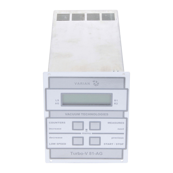
5. LCD back-lighted alphanumeric display: dot matrix 2 lines x 16 characters. Controller Turbo-V 81-AG Front Panel 87-900-986-01 (C) - Page 9 MAINTENANCE The Turbo-V 81-AG Rack series controller does not require any maintenance. Any work performed on the controller must be carried out by authorized personnel. When a fault has occurred it is possible to use the Varian repair service.
- Page 10 Press the START push-button twice to start faulty, or the Controller received a spike. the pump. Should the message still be present, call the Varian service. POWER FAIL Failure in the controller’s pump power Contact Varian for Maintenance. supply section. 87-900-986-01 (C)
-
Page 11: Turbo-V 81 Rack Controller Description
AIR COOLING KIT VENT EXT. EXTENTION CABLE CABLE CONTROLLER J2-SERIAL J4-PROFIBUS PUMP TO POWER MAINS FUSE TYPE T 4A SUPPLY VENT GAUGE MAINS CABLE GAUGE CABLE (1 m) GAUGE EXTENTION CABLE (5 m) GAUGE Turbo-V 81-AG Rack Controller – Connections 87-900-986-01 (C) -
Page 12: Controller Specifications
-20 °C to +70 °C CONTROLLER OUTLINE 0-95% Operating +5 - +45 °C The outline dimensions for the Turbo-V 81-AG Rack controllers are shown in the following figure. 0 – 90% NOTE NOTE The Turbo-V controller can be used as a bench unit or... -
Page 13: Controller Connection
This dedicated output optional Turbo-V 81-AG pump cooling fan (see orderable parts table). If you already have fan installed, use the available adapter cable to connect to the pump. Vent Connector This is dedicated 24 Vdc connector to control the optional vent valve (see orderable parts table). -
Page 14: P1 - Input
TECHNICAL INFORMATION P1 – Input All the logic input to the controller must be connected at J1 mating connector. With the provided J1 mating connector (shipped with pin 3 and pin 8 shorted) make the connections with AWG 24, (0.24 mm ) or smaller wire to the pins indicated in the figure to obtain the desired capability. -
Page 15: J1 - Output
TECHNICAL INFORMATION The following figure shows a typical contact logic input The following figure shows a typical logic output connection and the related simplified circuit of the controller. connection (relay coil) but any other device may be connected e.g. a LED, a computer, etc., and the related simplified circuit of the controller. - Page 16 TECHNICAL INFORMATION Pins Name Description Electrical Note 14-7 R2 Programmable Set Point Out Optically isolated Connect 10kohm Can be related to: Frequency, Power, Vmax (=open) = 24v resistor between the 2 Time Status or Pressure. Vlow, max = 1,5v pins before measuring See following figures for more details.
- Page 17 TECHNICAL INFORMATION Diagram 3 – R1 or R2 related to time V (Volt) R1-R2 Stop Waiting Ramp Auto Braking Normal Fail t (sec) Interlock tuning Diagram 4 – R1 or R2 related to Normal status Diagram 5 – R1 or R2 related to pressure reading (if gauge connected) 87-900-986-01 (C)
- Page 18 TECHNICAL INFORMATION PROGRAMMABLE ANALOG OUTPUT DIAGRAMS: V (Volt) Output Voltage 1350 Frequency (Hz) Diagram 1 – Programmable analog output related to frquency V (Volt) Output Voltage Power (W) Diagram 2 – Programmable analog output related to power V (Volt) Output Voltage Pump Temp (°C) Diagram 3 –...
-
Page 19: Pump Connector
TECHNICAL INFORMATION Pump Connector J5 – GAUGE CONNECTOR A five-meter long cable is available to connect the This connector is available to connect “EyeSys controller to the pump. The following figure shows the Mini-IMG” gauge with it’s extention cable (see controller output connector configuration where pins: orderable parts table). -
Page 20: Pump Driving
TECHNICAL INFORMATION Pump Driving J2 – SERIAL CONNECTOR Typical pump driving chart start and normal operation. This connector provides the connection for RS – 232 and RS – 485 serial line. J2 Pin-out: 1500 1250 1000 Freq. (Hz) Power. (W) - 12 PIN N. -
Page 21: Serial Communication Descriptions
Host = Master the metal shroud on the 0-subconnector. The cable should be secured to the connector with screws. Turbo-V 81-AG Controller = Slave The communication is performed in the following way: Serial Communication Descriptions Host... - Page 22 Pump cycles number (integer coded in 2 bytes) Answer = after a request from the host, the Speed threshold Turbo-V 81-AG controller will answer in one of the following Run up time in seconds ways: • (long coded in 4 bytes) •...
-
Page 23: Window Protocol
− <ETX> (End of transmission) = 0x03 On request a sample program in QBasic language is − <CRC> = XOR of all characters subsequent to available by Varian. <STX> and including the <ETX> terminator. The value is hexadecimal coded and indicated by two ASCII character. - Page 24 TECHNICAL INFORMATION The addressed SLAVE will respond with an ANSWER NOTE whose structure depends from the MESSAGE type. Using the RS 485 interface, the message structure When the MESSAGE is a reading command, the SLAVE remains identical to the one used for the RS 232 will respond transmitting a string with the same interface, the only difference being that the value structure of the MESSAGE.
-
Page 25: Window Meanings
TECHNICAL INFORMATION Window Meanings Examples: Command: START Read/ Data Description Admitted Source: PC Write Type Values Destination: Controller Start/Stop Start = 1 STX ADDR WINDOW Stop = 0 remote/Front Source: Controller mode the Destination: PC window is a read only) STX ADDR ACK ETX Low Speed No = 0... - Page 26 3 = Normal valve on/off Off = 0 4 = Pressure (on = closed) (default = 1) R2 Set Point Reserved to Varian service Value (Hz, W, s) Set the vent Automatic = 0 R2 Set Point (see note 1.)
- Page 27 0 to 9999 number (zeroed by the reset command) Pump life in 0 to 999999 hours (zeroed by the reset command) Reserved to Varian service QE8XXXX EPROM (where “XXXX” (QE) are variable) CRC Param. PA8XXXX (PA) (where “XXXX” are variable) "XXXX"...
-
Page 28: How To Use Front Panel
P U M P LOW SPEED START/STOP X X X X X X h Turbo-V 81-AG PUMP LIFE XXXXXX total operating time (hours) of the pump Start Stop and Reset Fail button – Pressing a third time, the following message Is... - Page 29 TECHNICAL INFORMATION P = X X X W X X X X H z P = X X X W X X X X H z T = X X X X E - Y Y m B a ° Where: Where: P= XXX W is the current power supplied to the...
-
Page 30: General
TECHNICAL INFORMATION N O R M A L X X X X H z General X X X X X X X X X X X X X X Make all vacuum manifold and electrical connections and refer to Turbo-V pump instruction manual before to operating the Turbo-V controller. -
Page 31: Startup
LOW SPEED START/STOP – Pressing the START button, the pump is started and Turbo-V 81-AG the display shows the following screen page. The following screen page is displayed on reaching the S T A R T X X X X H z... - Page 32 LOW SPEED START/STOP LOW SPEED START/STOP Turbo-V 81-AG Turbo-V 81-AG where P = is the DC power drawn by the pump (range 0 to 999 Watt) Where: = is the rotational speed of the pump as a...
-
Page 33: Programming
LOW SPEED START/STOP LOW SPEED START/STOP Turbo-V 81-AG Turbo-V 81-AG Where In programming mode, the meaning of the 4 buttons changes as follows: CYCLE XXXX Number of start/stop cycles TIME XXXXXm Time of last cycle (minutes) –... -
Page 34: Mode Menu
TECHNICAL INFORMATION Switching from a parameter to the previous parameter PUMP SETTING menu (using the “PREVIOUS” key) indicates the intention to abort any changes made to the specific parameter. Abort is indicated by the caption “ Changes aborted ” PUMP SETTING that is displayed for approx. -
Page 35: Input/Output Menu
TECHNICAL INFORMATION • • VENT VALVE MODE: makes it possible to select START MODE: Permits selection of one of the driving of the vent valve three types of functioning of the START/STOP and INTERLOCK inputs: AUTO TIME: the valve is controlled by the START/INTERLOCK: The pump is started if controller the START/STOP input is activated and is... -
Page 36: Gauge Menu
TECHNICAL INFORMATION • R1 (R2) OUTPUT LOGIC: Selects the control logic SETPOINT R1 and SETPOINT R2 submenus of the SETPOINT output. This submenu contains the settings relating to the _|-- positive logic (the relay is energized when the output with relay R1 (R2). measurement exceeds the reference) --|_ negative logic (the relay is energized when the measurement is below the reference) -
Page 37: Serial Menu
TECHNICAL INFORMATION SERIAL menu • This menu contains the settings for management of the BAUD RATE: permits selection RS232/485 serial line. communication speed selecting this from 600, 1200, 4800, 9600 baud • SERIAL MODE: permits setting of the type of interface to RS232 (point to point) or RS485 SERIAL BAUD RATE... -
Page 38: How To Use By Remote I/O
TECHNICAL INFORMATION HOW TO USE BY REMOTE I/O HOW TO USE IN SERIAL MODE Power ON the controller Power on the controller Connect the serial cable Press the “COUNTERS” and “MEASURES” button Select by front panel if you want to work in 232 or toghether. -
Page 39: Profibus Option
Each device has its own state machine to manage the device operation. The option works as a bi-directional bridge between the ProfiBus network and the Varian turbo controller internal link. The interface provides input data (measures) and output data (commands) to the... -
Page 40: Message Mapping
TECHNICAL INFORMATION Message mapping INTERNAL LINK STATE MACHINE The communication is based on the continuous data Status Meaning exchange capability of the ProfiBus standard, where POWER_ON Interface set-up the master sends continuously the entire slave configuration and reads back the entire slave status. SRC_ADDR Search for the controller serial address For this purpose one Input (from slave to master) and... -
Page 41: Parameter Buffer
Parameter Buffer Offset Size Unit Range Description WIN Serial Byte Byte 0-99 Gauge gas load type The value is divided by 10 (entering 12 the controller will apply 1.2) Enter here the correction factor for gas (necessary only if gauge is connected). mA/Hz/sec 0-10000 Setpoint 1 value... - Page 42 1 = On - Reserved = Start/Stop/Interlock Mode Change the logic of Start/Stop and Interlock inputs. Ask to Varian personnel for this option = Vent & Purge Auto/Man 0 = Auto (the controller drives purge and vent valves automatically) 1 = Manual (the user can command the valves by serial...
- Page 43 Offset Size Unit Range Description WIN Serial Byte Byte = Setpoint R1 Type 0 = frequency 1 = current 2 = time 3= normal operation 4= pressure = Setpoint R2 Type 0 = frequency 1 = current 2 = time 3= normal operation 4= pressure =Analog Output 1 Type...
-
Page 44: Output Buffer
Output Buffer Offset Size Unit Range Description WIN Serial Byte Byte = Start/Stop 0 = Stop, 1 = Start = Low Speed This bit set the pump target speed to “low speed value” (Output Buffer, Offset 3), otherwise the target speed is set to “high speed value”... -
Page 45: Input Buffer
Input Buffer Offset Size Unit Range Description WIN Serial Byte Byte 0-100 Voltage Voltage provided to the motor °C 0-100 Pump Bearing Temperature Read the pump upper bearing temperature If > 60°C the controller goes into fail status and the pump is stopped °C 0-100... - Page 46 Offset Size Unit Range Description WIN Serial Byte Byte – Set Point R1 Status 0 = open 1 = closed – Set Point R2 Status 0 = open 1 = closed – Vent Valve Status 0 = closed 1 = open –...
-
Page 47: Diagnostic Management
TECHNICAL INFORMATION Diagnostic management Diagnostic buffer In addition to the ProfiBus six byte standard diagnostic, the interface provides both user diagnostic and static Meaning diagnostics functions station non exist (set by master) The standard diagnostic management is fully compliant station not ready (slave not ready for with the ProfiBus specification. -
Page 48: Error Messages
TECHNICAL INFORMATION ERROR MESSAGES NOTE For a certain type of failure, the controller will self- If the upper bearing/pump temperature exceeds diagnose the error and the following messages will be 60 °C, the pump is shut off, and the display will be as displayed. -
Page 49: Orderable Parts
Turbo-V 81-AG with Profibus option 969-8990 Turbo-V 81-AG Air Cooling Kit (0.5 m cable) 969-9290 Turbo-V 81-AG Air Cooling Kit extention cable (5 m) 969-9940 Vent Valve N.O. 0,5 mm orifice (0,5 m cable) 969-9844 Vent Valve extention cable (5 m) - Page 50 NOTE: If a product is received at Varian which is contaminated with a toxic or hazardous material that was not disclosed, the customer will be held responsible for all costs incurred to ensure the safe handling of the product, and is liable for any harm or injury to Varian employees as well as to any third party occurring as a result of exposure to toxic or hazardous materials present in the product.
- Page 51 Request for Return FAILURE REPORT TURBO PUMPS and TURBOCONTROLLERS POSITION PARAMETERS Power: Rotational Speed: Does not start Noise Vertical Current: Inlet Pressure: Does not spin freely Vibrations Horizontal Temp 1: Foreline Pressure: Does not reach full speed Leak Upside-down Mechanical Contact Overtemperature Other: Temp 2:...
- Page 52 Toll Free # 1 (800) 882 7426 Tel: 00 800 234 234 00 vtt.technical.support@varianinc.com China Mexico Varian Technologies - Beijing Varian, S. de R.L. de C.V. Rm 1648 Central Tower South Wing Concepcion Beistegui No 109 China Beijing Junefield Plaza Col Del Valle No.