
Related Manuals for Arcus DMX-K-SA


Summary of Contents for Arcus DMX-K-SA
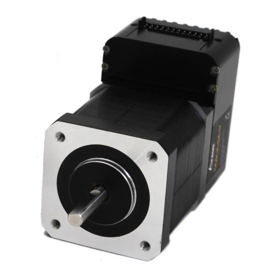
- Page 1 DMX-K-SA Integrated Step Motor Encoder/Driver/Controller Manual DMX-K-SA-17/23 Manual page 1 rev 3.18...
- Page 2 3.18 – 5 Release Firmware Compatibility: †V340BL †If your module’s firmware version number is less than the listed value, contact Arcus for the appropriate documentation. Arcus reserves the right to change the firmware without notice. DMX-K-SA-17/23 Manual page 2 rev 3.18...
-
Page 3: Table Of Contents
Torque Curve – NEMA 23 ................... 13 5. Connections........................15 24-Pin Connector (2mm) ....................15 Junction Board ......................16 DMX-K-SA-17/23 Interface Circuit ................17 Digital Outputs ......................18 Digital Inputs ........................ 18 6. Getting Started ......................19 Typical Setup ........................ 19 RS-232 .......................... - Page 4 10. Standalone Language Specification ................55 ; ............................. 55 ABORTX ........................55 ABS ..........................55 ACC ..........................55 DEC..........................56 DELAY ......................... 56 DI ..........................56 DI[1-6] .......................... 57 DO ..........................57 DO[1-3] ......................... 57 DRVIC .......................... 58 DMX-K-SA-17/23 Manual page 4 rev 3.18...
- Page 5 SYNOFFX ........................69 SYNONX ........................69 SYNPOSX ........................69 SYNSTATX ........................70 SUB ..........................70 TOC..........................70 V[0-99] .......................... 71 WAITX ......................... 71 WHILE .......................... 72 X ............................ 72 ZHOMEX[+ or -] ......................73 DMX-K-SA-17/23 Manual page 5 rev 3.18...
- Page 6 Standalone Example Program 6 – Single Thread ............76 Standalone Example Program 7 – Multi Thread............77 Standalone Example Program 8 – Multi Thread............78 Appendix A: Speed Settings ..................... 79 Acceleration/Deceleration Range ................. 79 Acceleration/Deceleration Range – Positional Move ........... 80 DMX-K-SA-17/23 Manual page 6 rev 3.18...
-
Page 7: Introduction
DMX-K-SA is an all-in-one integrated motor package that combines all the motion components in to one convenient package. Communication to the DMX-K-SA can be established over RS-232 or RS-485. It is also possible to download a stand-alone program to the device and have it run independent of a host. -
Page 8: Model Numbers
Motor Size 17 – NEMA 17 Motor 23 – NEMA 23 Motor SA - Standalone K – K Series Contacting Support For technical support contact: support@arcus-technology.com. Or, contact your local distributor for technical support. DMX-K-SA-17/23 Manual page 8 rev 3.18... -
Page 9: Electrical And Thermal Specifications
45 mA † Includes limit, home and latch Digital Outputs Type: Opto-isolated open-collector NPN outputs Max voltage at collector: +24 VDC Max source current at 24VDC †90 mA † A current limiting resistor is required DMX-K-SA-17/23 Manual page 9 rev 3.18... -
Page 10: Dimensions
3. Dimensions †All dimensions in inches DMX-K-SA-17 Figure 3.0 DMX-K-SA-23 Figure 3.1 DMX-K-SA-17/23 Manual page 10 rev 3.18... - Page 11 Model L (inches) DMX-K-SA-17-2 1.58 DMX-K-SA-17-3 1.89 DMX-K-SA-23-2 DMX-K-SA-23-3 Table 3.0 DMX-K-SA-17/23 Manual page 11 rev 3.18...
-
Page 12: Motor Specifications
Double 2.8A 0.95 N-m 2.5 mH 1.64 oz-in Triple 2.8A 1.41 N-m 1.13 3.6 mH 2.62 oz-in Table 4.0 † Motor current specifications are in RMS form. Torque Curve – NEMA 17 Figure 4.0 DMX-K-SA-17/23 Manual page 12 rev 3.18... -
Page 13: Torque Curve - Nema 23
Figure 4.1 Torque Curve – NEMA 23 Figure 4.2 DMX-K-SA-17/23 Manual page 13 rev 3.18... - Page 14 Figure 4.3 DMX-K-SA-17/23 Manual page 14 rev 3.18...
-
Page 15: Connections
Digital Output 1 +LIM Plus limit input RS-232 RXD signal -LIM Minus limit input Digital Input 1 Digital Input 3 DI2/LT Digital Input 2 / Latch Digital Input 4 No Connection Digital Input 5 DMX-K-SA-17/23 Manual page 15 rev 3.18... -
Page 16: Junction Board
Junction Board JBD-K-SA is a junction board that allows users to easily access the signals on the DMX- K-SA. The accessory comes with a 1ft long cable to connect to the DMX-K-SA. JBD-K-SA is not included in the purchase of DMX-K-SA. -
Page 17: Dmx-K-Sa-17/23 Interface Circuit
DMX-K-SA-17/23 Interface Circuit Figure 5.2 DMX-K-SA-17/23 Manual page 17 rev 3.18... -
Page 18: Digital Outputs
The maximum sink current for digital outputs is 90 mA. Take caution to WARNING: select the appropriate external supply and pull-up resistance to limit the sink current below this level. Digital Inputs Figure 5.4 shows the detailed schematic of the opto-isolated inputs. Figure 5.4 DMX-K-SA-17/23 Manual page 18 rev 3.18... -
Page 19: Getting Started
6. Getting Started Typical Setup Figure 6.0 There are two ways to communicate with DMX-K-SA series product: RS-232 and RS- 485. RS-232 When the DMX-K-SA unit is shipped from the factory, default communication setting is RS-232 at 9600 baud rate. - Page 20 When communicating via RS-485, it is recommended to add a 120 Ohm terminating resistor between 485+ and 485- signal on the last module. Below is a typical RS-485 master and multi-slave network. Figure 6.2 DMX-K-SA-17/23 Manual page 20 rev 3.18...
-
Page 21: Windows Gui
RXD of the serial port and RXD from DMX-K-SA should be connected to TXD of serial port. If using RS-485, make sure that the 485+ from DMX-K-SA is connected to 485+ of the master and 485- from DMX-K-SA is connected to 485- of the master. -
Page 22: Main Control Screen
• Confirm that the device name is set correctly. Default factory device name setting is “01”. If this name has been changed and stored to flash, enter the new name. Main Control Screen Figure 6.4 DMX-K-SA-17/23 Manual page 22 rev 3.18... -
Page 23: Status
MOVING: target move is in progress JOGGING: jog move is in progress HOMING: homing is in progress LHOMING: limit homing in progress Z-HOMING: homing using Z-index channel in progress ERR-STALL: StepNLoop has stalled. ERR-LIM: plus/minus limit error DMX-K-SA-17/23 Manual page 23 rev 3.18... -
Page 24: Control
High/Low Speed: use this to set the speed of the move. For normal open loop mode, this value is in pulses/second and when StepNLoop is enabled this value is in encoder counts/second DMX-K-SA-17/23 Manual page 24 rev 3.18... -
Page 25: Digital Input / Output
ZH: homing is done using the home switch first and then the Z index channel of the encoder. Z: homing is done only using the Z index channel of the encoder. C. Digital Input / Output Figure 6.7 1. Digital Input Status – digital inputs DMX-K-SA-17/23 Manual page 25 rev 3.18... -
Page 26: Communication
Figure 6.8 1. Communication Status – Displays communication status with the selected device. 2. Device ID – Device ID of the communicating DMX-K-SA. To communicate with a different DMX-K-SA on-the-fly, select another ID number from this drop-down box. E. Product Info Figure 6.9... -
Page 27: Terminal
Figure 6.10 1. Response Window – Displays the response, if any, from the command line 2. Address – Select the address of the DMX-K-SA module which you wish to communicate. Selecting address ‘00’ will send a broadcast command which will be received by all DMX-K-SA modules on a RS-485 bus. -
Page 28: Setup
Alarm: Alarm output (used when StepNLoop is enabled and EDO=1) Output: digital output polarity Input: digital input polarity SA Err: stand-alone error jump line. • Low: jump to previous line • High: jump to line 0 Enable: motor enable output polarity DMX-K-SA-17/23 Manual page 28 rev 3.18... -
Page 29: Standalone Program File Management
Note that if the configuration values are changed, it needs to be downloaded to take effect. 8. Store – The downloaded parameters can be permanently stored on the non- volatile memory. H. Standalone Program File Management Figure 6.12 1. Open – Open standalone program DMX-K-SA-17/23 Manual page 29 rev 3.18... -
Page 30: Standalone Program Editor
1. Write the standalone program in the Program Editor 2. Use this button to remove the current standalone program Use this button to open a larger and easier to manage program editor. J. Standalone Processing Figure 6.14 DMX-K-SA-17/23 Manual page 30 rev 3.18... -
Page 31: Variable Status
1. Command line – To write to variable, use V[0-99] = [value] syntax. L. Program Control Figure 6.16 1. Program Status – program status shows here. Following are possible program status: Idle, Running, Errored and Paused. DMX-K-SA-17/23 Manual page 31 rev 3.18... -
Page 32: On-The-Fly Speed Change
Figure 6.18 Click this button to display the GUI version as well as the firmware version of the controller/driver. If the firmware version is not up to date, the unsupported features will be listed. DMX-K-SA-17/23 Manual page 32 rev 3.18... -
Page 33: Motion Control Overview
EX command returns encoder position PX command returns pulse position Built-in Microstep Driver DMX-K-SA has an integrated micro-step driver. The micro-step setting is fixed at 16. With a 1.8° motor, this results in a 3200 step/rev resolution. Motion Profile By default, a trapezoidal velocity profile is used. See Figure 7.0. -
Page 34: On-The-Fly Speed Change
For non on-the-fly speed change moves, set SSPDM=0. Digital Inputs/Outputs DMX-K-SA comes with 6 digital inputs and 3 digital outputs. Inputs Read digital input status using the DI command. Digital input values can also be referenced one bit at a time by the DI[1-6] commands. -
Page 35: Motor Power
The initial state the enable output can be defined by setting the EOBOOT register to the desired initial value. The value is stored to flash memory once the STORE command is issued. Polarity Using the POL command, polarity of following signals can be configured: Description Reserved Direction Reserved Reserved DMX-K-SA-17/23 Manual page 35 rev 3.18... -
Page 36: Positional Moves
SUB31 is called will be line 0. Otherwise, it will be the line that caused the error. Positional Moves DMX-K-SA can operate in either incremental or absolute move modes. Use X command to make moves. Use INC and ABS commands to set the move mode. Use MM command to read the current move mode. -
Page 37: Homing
Homing Home search sequence involves moving the motor towards the home or limit switches and then stopping when the relevant input is detected. The DMX-K-SA has five different homing routines: Home Input Only (High Speed Only) Use the H+/H- command. Figure 7.2 shows the homing routine. -
Page 38: Home Input Only (High Speed And Low Speed)
F. The home input is triggered again, the position counter is reset to zero and the motor stops immediately Note: For H, HL homing routines, it is possible to have the motor automatically return to the zero position. To do so, set the RZ=1. DMX-K-SA-17/23 Manual page 38 rev 3.18... -
Page 39: Limit Only
Use the Z+/Z- command. Figure 7.6 shows the homing routine. Figure 7.6 A. Issuing the command starts the motor at low speed. B. Once the z-index pulse is found, the motor stops and the position is set to zero. DMX-K-SA-17/23 Manual page 39 rev 3.18... -
Page 40: Motor Position
The limit error state can be ignored by setting IERR=1. In this case, the motor will still stop when the limit switch is triggered; however, it will not enter an error state. DMX-K-SA-17/23 Manual page 40 rev 3.18... -
Page 41: Latch Input
LTE (latched encoder position) commands. Sync Output DMX-K-SA has a designated synchronization digital output (DO2). The synchronization signal output is triggered when the encoder position value meets the set condition. While this feature is enabled, the designated digital output (DO2) cannot be controlled by user. -
Page 42: Stepnloop Closed Loop Control
StepNLoop Closed Loop Control DMX-K-SA features a closed-loop position verification algorithm called StepNLoop (SNL). The algorithm requires the use of an incremental encoder. SNL performs the following operations: 1) Position Verification: At the end of any targeted move, SNL will perform a correction if the current error is greater than the tolerance value. - Page 43 X1000 means to move the motor to encoder 1000 position. Once SNL is enabled, the speed is in encoder speed. For example HSPD=1000 when SNL is enabled means that the target high speed is 1000 encoder counts per second. DMX-K-SA-17/23 Manual page 43 rev 3.18...
-
Page 44: Idle Current And Run Current
Device name is set to: DMK01 Baud Rate Setting DMX-K-SA provides the user with the ability to set the desired baud rate of the serial communication. In order to make these changes, first store the desired baud rate by using the DB command. -
Page 45: Broadcasting Over Rs-485
The address ‘00’ is reserved for broadcasting over an RS-485 bus. Any ASCII command prefixed by ‘@00’ will be processed by all DMX-K-SA modules on the RS-485 bus. When a broadcast command is received by a DMX-K-SA module, no response is sent back to the master. -
Page 46: Auto-Response Feature
Auto-response Feature It is possible to have the DMX-K-SA automatically send a message out on the RS- 232/485 bus once it is in position. This feature prevents the master from having to constantly poll the position status of the DMX-K-SA. -
Page 47: Communication Time-Out Feature (Watchdog)
Table 7.10 Communication Time-out Feature (Watchdog) DMX-K-SA allows for the user to trigger an alarm if the master has not communicated with the device for a set period of time. When an alarm is triggered bit 10 of the MST parameter is turned on. -
Page 48: Storing To Flash
Following are the factory default settings when then unit is shipped from the factory. Parameter Description Command Value Auto-response for in-position Disabled Communication Method RS-232 CURI Idle Current 1000 mA CURR Run Current 1600 mA CURT Idle Time 500 mSec DMX-K-SA-17/23 Manual page 48 rev 3.18... - Page 49 Return to home position Disabled StepNLoop Enabled StepNLoop Maximum Attempt StepNLoop Error Range 1000 StepNLoop Idle Tolerance SLOAD Run Program(s) on Power Up StepNLoop Tolerance Range Time-out counter value (Watch-dog) V50-V99 Non-volatile variables Table 7.12 DMX-K-SA-17/23 Manual page 49 rev 3.18...
-
Page 50: Communication Protocol
The address ‘00’ is reserved for broadcasting over a RS-485 bus. Any ASCII command prefixed by ‘@00’ will be processed by all DMX-K-SA modules on the RS-485 bus. When a broadcast command is received by a DMX-K-SA module, no response is sent back to the master. -
Page 51: Ascii Language Specification
Refer to the “Standalone Language Specification” section for details regarding stand-alone commands. DMX-K-SA language is case sensitive. All command should be in capital letters. Invalid command is returned “?”. Always check for proper reply when command is sent. - Page 52 PX=[value] Sets the current position value Get Modbus enable 0 or 1 RSM= [0 or 1] Set Modbus enable Get response type value 0 or 1 RT= [0 or 1] Set response type value DMX-K-SA-17/23 Manual page 52 rev 3.18...
- Page 53 Set sync output configuration 1 – trigger when encoder equals position 2 – trigger when encoder is LESS than position 3 – trigger when encoder is GREATER than position SYNF Turn off sync output DMX-K-SA-17/23 Manual page 53 rev 3.18...
-
Page 54: Error Codes
Homes the motor in negative direction using the home switch and then Z index encoder channel. Table 9.0 Error Codes If an ASCII command cannot be processed by the DMX-K-SA, the controller will reply with an error code. See below for possible error responses: Error Code Description... -
Page 55: Standalone Language Specification
Read: [variable] = ACC Write: ACC = [value] ACC = [variable] Examples: ACC=300 ;***Sets the acceleration to 300 milliseconds V3=500 ;***Sets the variable 3 to 500 ACC=V3 ;***Sets the acceleration to variable 3 value of 500 DMX-K-SA-17/23 Manual page 55 rev 3.18... -
Page 56: Dec
;***Jogs axis to positive direction DELAY=10000 ;***Wait 10 second ABORTX ;***Stop axis Description: Read: Gets the digital input value. DMX-K-SA has 6 digital inputs. Digital inputs are active high Syntax: Read: [variable] = DI Conditional: IF DI=[variable] ENDIF IF DI=[value]... - Page 57 DI[1-6] Description: Read: Gets the digital input value. DMX-K-SA has 6 digital inputs. Syntax: Read: [variable] = DI[1-6] Conditional: IF DI[1-6]=[variable] ENDIF IF DI[1-6]=[0 or 1] ENDIF Examples: IF DI1=0 DO=1 ;***If digital input 1 is triggered, set DO=1 ENDIF...
-
Page 58: Drvic
ECLEARX Description: Write: Clears motor error status. Also clears a StepNLoop error. Syntax: Write: ECLEARX Examples: ECLEARX ;***Clears motor error ELSE Description: Perform ELSE condition check as a part of IF statement Syntax: ELSE DMX-K-SA-17/23 Manual page 58 rev 3.18... -
Page 59: Elseif
< Less than >= Greater than or equal to <= Less than or equal to Not Equal to Examples: IF V1=1 X1000 WAITX ELSEIF V1=2 X2000 WAITX ELSEIF V1=3 X3000 WAITX ELSE WAITX ENDIF DMX-K-SA-17/23 Manual page 59 rev 3.18... -
Page 60: End
When ENDSUB is reached, the program returns to the previously called subroutine. Subroutine definitions should be written AFTER the END statement Notes: Sub 31 is reserved for error handling Syntax: ENDSUB Examples: GOSUB 1 SUB 1 WAITX X1000 WAITX ENDSUB DMX-K-SA-17/23 Manual page 60 rev 3.18... -
Page 61: Endwhile
Write: Sets the current encoder position Syntax: Read: [variable] = E[axis] Write: EX = [value] EX = [variable] Conditional: IF EX=[variable] ENDIF IF EX=[value] ENDIF Examples: EX=0 ;***Sets the current encoder position to 0 DMX-K-SA-17/23 Manual page 61 rev 3.18... -
Page 62: Gosub
HLHOMEX+ ;***Homes the motor at low speed in the positive direction WAITX HOMEX[+ or -] Description: Command: Perform homing using current high speed, low speed, and acceleration. Syntax: HOMEX[+ or -] Examples: HOMEX+ ;***Homes axis in positive direction WAITX DMX-K-SA-17/23 Manual page 62 rev 3.18... -
Page 63: Hspd
[Comparison] can be any of the following Equal to > Greater than < Less than >= Greater than or equal to <= Less than or equal to Not Equal to Examples: IF V1=1 X1000 ENDIF DMX-K-SA-17/23 Manual page 63 rev 3.18... -
Page 64: Inc
Examples: LHOMEX+ ;***Limit homes axis in positive direction WAITX LSPD Description: Read: Get low speed. Value is in pulses/second. Write: Set low speed. Value is in pulses/second. Syntax: Read: [variable]=LSPD Write: LSPD=[long value] LSPD=[variable] DMX-K-SA-17/23 Manual page 64 rev 3.18... -
Page 65: Ltx
Read: Get latch encoder value Syntax: Read: [variable]=LTEX Examples: See LTX LTPX Description: Read: Get latch position value Syntax: Read: [variable]=LTPX Examples: See LTX LTSX Description: Read: Get latch status Syntax: Read: [variable]=LTSX Examples: See LTX DMX-K-SA-17/23 Manual page 65 rev 3.18... -
Page 66: Mstx
Syntax: Read: Variable = PS Conditional: IF PS=[variable] ENDIF IF PS=[value] ENDIF Examples: JOGX+ ;***Jogs axis to positive direction DELAY=1000 ;***Wait 1 second ABORTX ;***Stop without deceleration V1=PS ;***Sets variable 1 to pulse speed DMX-K-SA-17/23 Manual page 66 rev 3.18... -
Page 67: Scvx
ENDIF SSPDX Description: Write: Set on-the-fly speed change for an individual axis. Syntax: Write: SSPDX=[value] SSPDX=[variable] Note: If s-curve is enabled for an axis, on-the-fly speed feature cannot be used for the corresponding axis. DMX-K-SA-17/23 Manual page 67 rev 3.18... -
Page 68: Sspdmx
;***Wait 1 second STOPX ;***Stop with deceleration STORE Description: Command: Store all values to flash Syntax: STORE Examples: V80=EX ;***Put encoder value in V80 DELAY=1000 ;***Wait 1 second STORE ;***Store V80 to non-volatile flash DMX-K-SA-17/23 Manual page 68 rev 3.18... -
Page 69: Syncfgx
Syntax: Write: SYNOFFX Examples: See SYNCFGX SYNONX Description: Write: Enable sync output feature Syntax: Write: SYNONX Examples: See SYNCFGX SYNPOSX Description: Write: Set sync output position. Syntax: Write: SYNPOSX=[value] Write: SYNPOSX=[variable] Examples: See SYNCFGX DMX-K-SA-17/23 Manual page 69 rev 3.18... -
Page 70: Synstatx
[Subroutine Number] range is 0 to 31 Examples: GOSUB 1 SUB 1 WAITX X1000 WAITX ENDSUB Description: Write: Set deceleration value. Value is in milliseconds. Syntax: Write: TOC = [value] Examples: TOC=300 ;***Sets the time-out watchdog to 300 milliseconds DMX-K-SA-17/23 Manual page 70 rev 3.18... -
Page 71: Waitx
V[0-99] Description: Assign to variable. DMX-K-SA has 100 variables [V0-V99] Syntax: V[Variable Number] = [Argument] V[Variable Number] = [Argument1][Operation][Argument2] Special case for BIT NOT: V[Variable Number] = ~[Argument] [Argument] can be any of the following: Numerical value Pulse or Encoder Position... -
Page 72: While
Perform X axis move to target location Command: Syntax: X[value] X[variable] Examples: ;***Absolute move mode X10000 ;***Move to position 10000 WAITX V10 = 1200 ;***Set variable 10 value to 1200 XV10 ;***Move axis to variable 10 value WAITX DMX-K-SA-17/23 Manual page 72 rev 3.18... -
Page 73: Zhomex[+ Or -]
Command: Perform Zoming (homing only using Z-index) using current high speed, low speed, and acceleration. Syntax: ZOMEX[+ or -] Examples: ZOMEX+ ;***Zomes axis in positive direction WAITX ZOMEX- ;***Zomes axis in negative direction WAITX DMX-K-SA-17/23 Manual page 73 rev 3.18... -
Page 74: Example Standalone Programs
;* Loop while variable 1 is less than 10 X1000 ;* Move to zero WAITX ;*Wait for X-axis move to complete ;* Move to 1000 V1=V1+1 ;* Increment variable 1 ENDWHILE ;* Go back to WHILE statement DMX-K-SA-17/23 Manual page 74 rev 3.18... -
Page 75: Standalone Example Program 4 - Single Thread
SUB 1 ;* Move to V1 target position V1=V1+1000 ;* Increment V1 by 1000 WHILE DI1=1 ;* Wait until the DI1 is turned off so that ENDWHILE ;* 1000 increment is not continuously done ENDSUB DMX-K-SA-17/23 Manual page 75 rev 3.18... -
Page 76: Standalone Example Program 6 - Single Thread
;* Home the motor in negative direction ENDIF V1=MSTX ;* Store the motor status to variable 1 V2=V1&7 ;* Get first 3 bits IF V2!=0 DO1=1 ELSE DO1=0 ENDIF ENDWHILE ;* Go back to WHILE statement DMX-K-SA-17/23 Manual page 76 rev 3.18... -
Page 77: Standalone Example Program 7 - Multi Thread
;* Stop Program 1 ELSE ;* If digital input 1 is not triggered SR0=1 ;* Run Program 1 ENDIF ;* End if statements ENDWHILE ;* Go back to WHILE statement ;* End Program 1 DMX-K-SA-17/23 Manual page 77 rev 3.18... -
Page 78: Standalone Example Program 8 - Multi Thread
;* Abort the motor DO=0 ;* Set DO=0 DELAY=3000;* Delay 3 seconds SR0=1 ;* Turn program 0 back on DO=1 ;* Set DO=1 ENDIF ENDWHILE ;* Go back to WHILE statement ;* End Program 1 DMX-K-SA-17/23 Manual page 78 rev 3.18... -
Page 79: Appendix A: Speed Settings
Min acceleration allowable: 1 ms b. Max acceleration allowable: ((20,000 – 100) / 1,000) x 1,000 ms = 19900 ms (19.9 sec) b) If HSPD = 900,000 pps, LSPD = 1000 pps: a. Min acceleration allowable: 1 ms DMX-K-SA-17/23 Manual page 79 rev 3.18... -
Page 80: Acceleration/Deceleration Range - Positional Move
L/2, the acceleration value is used for both ramp up and ramp down. This is regardless of the EDEC setting. 3) Triangle Profile: If either (1) or (2) occur, the velocity profile becomes triangle. Maximum speed is reached at L/2. DMX-K-SA-17/23 Manual page 80 rev 3.18... - Page 81 Contact Information Arcus Technology, Inc. 3159 Independence Drive Livermore, CA 94551 925-373-8800 www.arcus-technology.com The information in this document is believed to be accurate at the time of publication but is subject to change without notice. DMX-K-SA-17/23 Manual page 81 rev 3.18...
Need help?
Do you have a question about the DMX-K-SA and is the answer not in the manual?
Questions and answers