
Subscribe to Our Youtube Channel
Related Manuals for Arcus DMX-CAN-23


Summary of Contents for Arcus DMX-CAN-23
- Page 1 DMX-CAN-23 Integrated Step Motor Encoder/Driver/Controller Manual DMX-CAN Manual page 1 rev 1.6...
- Page 2 ARCUS. ARCUS makes no representations or warranties regarding the content of this document. We reserve the right to revise this document any time without notice and obligation.
-
Page 3: Table Of Contents
4. Motor Specifications ....................... 9 Electrical Specifications....................9 Torque Curve – NEMA 23 ..................... 9 5. Connections........................11 24-Pin Connector (2mm) ....................11 DMX-CAN-23 Interface Circuit ................... 13 Digital Outputs ......................14 Digital Inputs ........................ 14 6. Getting Started ......................15 RS-232 Communication....................15 RS-485 Communication.................... - Page 4 Sync Output ........................36 StepNLoop Closed Loop Control ................. 37 Idle Current and Run Current ..................39 RS-232/RS-485/CANopen Selection: ................39 Node ID, Device Number, and Baud Rate:..............39 Broadcasting over RS-485 .................... 40 Response type selection ....................40 Storing to Flash ......................41 Default Settings ......................
-
Page 5: Introduction
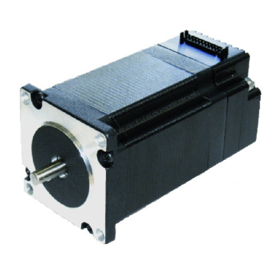
DMX-CAN is an all-in-one integrated motor package that combines all the motion components in to one convenient package. Communication to the DMX-CAN can be established over RS-232, RS-485 or CANbus. Features DMX-CAN-23 RS-485 + RS-232 ASCII communication • 9600, 19200, 38400, 57600, 115200 bps CANbus communication over CANOpen implementing CiA DSP-402 •... -
Page 6: Model Numbers
DMX-CAN- 23 - Motor Stack Size 2 – Double 3 – Triple Motor Size 23 – NEMA 23 Motor CAN Series Contacting Support For technical support contact: support@arcus-technology.com. Or, contact your local distributor for technical support. DMX-CAN Manual page 6 rev 1.6... -
Page 7: Electrical And Thermal Specifications
2. Electrical and Thermal Specifications Power Requirement Regulated Voltage: +12 to +35 VDC Current (Max): 2.5 A (peak) Temperature Ratings † Operating Temperature: 0°C to +70°C Storage Temperature: -55°C to +150°C † Based on component ratings Digital Inputs † Type: Opto-isolated NPN inputs Opto-isolator supply: +12 to +24 VDC... -
Page 8: Dimensions
3. Dimensions †All dimensions in inches DMX-CAN-23 Figure 3.0 All dimensions in inches Model L (inches) DMX-K-SA-23-2 DMX-K-SA-23-3 Table 3.0 DMX-CAN Manual page 8 rev 1.6... -
Page 9: Motor Specifications
4. Motor Specifications Electrical Specifications NEMA Stack Current / Holding Resistance/ Inductance/ Inertia Size Size Phase † Torque Phase Phase Double 2.8A 0.95 N-m 2.5 mH 1.64 oz-in Triple 2.8A 1.41 N-m 1.13 3.6 mH 2.62 oz-in Table 4.0 † Motor current specifications are in RMS form. Torque Curve –... - Page 10 Figure 4.1 DMX-CAN Manual page 10 rev 1.6...
-
Page 11: Connections
5. Connections 24-Pin Connector (2mm) Figure 5.0 Pin # In/Out Name Description +12 to +35VDC power input +12 to +35VDC power input. Shorted to pin 1 Ground 485+ RS-485 plus signal HOME Home input 485- RS-485 minus signal DO1/INP Digital Output 1 +LIM Plus limit input RS-232 RXD signal... - Page 12 Digital Input 6 RS-232 TXD signal Digital Output 2 OPTOGND Opto-supply ground DO3/ALM Digital Output 3 / Alarm CAN-L CAN-L Ground. Shorted to pin 3 Table 5.0 Mating Connector Description: 24 pin 2mm dual row connector Mating Connector Manufacturer: HIROSE Mating Connector Housing Part Number: DF11-24DS-2C Mating Connector Pin Part Number:...
-
Page 13: Dmx-Can-23 Interface Circuit
DMX-CAN-23 Interface Circuit Figure 5.1 DMX-CAN Manual page 13 rev 1.6... -
Page 14: Digital Outputs
Digital Outputs Figure 5.2 shows an example wiring to the digital output. Figure 5.2 WARNING: The maximum sink current for digital outputs is 90 mA. Take caution to select the appropriate external supply and pull-up resistance to limit the sink current below this level. -
Page 15: Getting Started
6. Getting Started There are three ways to communicate with DMX-CAN series product: RS-232, RS-485, and CANopen. RS-232 Communication When the DMX-CAN unit is shipped from the factory, default communication setting is RS-232 at 9600 baud rate. Note that RS-232 is a point-to-point protocol. See figure below: Figure 6.0 RS-485 Communication If RS-485 communication is required, first you need to communicate using RS-232 and... -
Page 16: Canopen Communication
Figure 6.1 CANOpen Communication If CANOpen communication is required, first you need to communicate using RS-232 and use the Windows program to change the communication method to CANOpen, download the setup, and store to flash. Once communication method is changed, you need to reboot the module for the new parameter to take effect and then communicate through CANopen. -
Page 17: Windows Gui
Figure 6.2 Windows GUI DMX-CAN comes with user friendly Windows Program to quickly communicate, test, program, and debug the DMX-CAN unit. Start the DMX-CAN program and following dialog box will show. Figure 6.3 DMX-CAN Manual page 17 rev 1.6... - Page 18 A. Serial Communication Port Number. This is a drop down combo box which has selection of serial port from COM1 to COM15. B. 9600 baud rate is the default communication baud rate that is used. If you have set your DMX-CAN module to operate at a different baud rate, select the correct baud rate here.
- Page 19 When Open Connection button is pressed and communication is successfully established, following screen will show: Figure 6.4 DMX-CAN Manual page 19 rev 1.6...
- Page 20 A. Status Figure 6.5 1. Current pulse position (when StepNLoop is enabled, pulse position is defined as the current target position) 2. Current encoder position 3. Delta position – this is the difference between the target position and actual position. 4.
- Page 21 7. Mode i. ABS – Target movement moves to the absolute target position ii. INC – Target movement increments/decrements by the target position amount 8. Current – displays active current value. Value is in mA. 9. S-curve enable status 10. –Limit, +Limit, and Home input status 11.
- Page 22 and the motor decelerates to low speed and stops. After homing, the position is not necessarily zero due to deceleration after the trigger of the home switch. 11. ZH+/ZH- - Home sensor and encoder index channel is used to home. 12.
- Page 23 D. Product ID & Firmware Figure 6.8 Displays the product ID of DMX-CAN as well as the firmware version of the module. E. Communication Figure 6.9 1. Communication Status – Displays communication status with the selected device. 2. Device ID – Device ID of the communicating DMX-CAN. To communicate with a different DMX-CAN on-the-fly, select another ID number from this drop-down box.
- Page 24 G. Sync Output Figure 6.11 1. Enable Sync Output 2. Status is either OFF, ON, WAITING 3. The sync position used for comparison to the encoder position 4. Set the conditional used for the Sync output. Once this condition is met, the sync output (DO2) is activated.
- Page 25 Figure 6.12 1. Response Window – Displays the response from the command line 2. Address – Select the address of the DMX-CAN module which you wish to communicate. Selecting address ‘00’ will send a broadcast command which will be received by all DMX-CAN modules on a RS- 485 bus.
- Page 26 I. Setup DMX-CAN configuration values are automatically loaded when the program is started. All the configuration changes are uploaded and download all at once. This means that in order for the configuration to become effective, download button must be pressed. In order for the configuration to be permanent, store to flash must be pressed.
- Page 27 4. CAN Node ID – CAN Node ID ranges from 1 to 127. 5. Limit Correction Amount – Set limit correction amount. See detailed description in Home Limit Error Correction section. 6. Current values – Run current is used when the motor is running. Idle current is used when the Idle time expires.
- Page 28 1. Enter new target position here. 2. Start on-the-fly-position change operation. K. On-The-Fly-Speed Figure 6.15 1. Desired Speed – Once the “Set Speed” button is clicked, the speed will change on-the-fly to the desired speed. 2. Desired Acc/Dec – The acceleration/deceleration use for the on-the-fly speed change operation 3.
-
Page 29: Motion Control Overview
7. Motion Control Overview Important Note: All the commands described in this section are for ASCII communication over a RS-232/RS-485 network. For details on communication over CANOpen, please see the "Object Dictionary [CANOpen]" section. Built-in encoder DMX-CAN comes with a 1000 line encoder. With quadrature decoding, 4000 count/rev resolution is reached. -
Page 30: Digital Inputs/Outputs
S-curve velocity profile can also be achieved by using the SCV command. See Figure 7.1. Figure 7.1 Notes: The minimum and maximum acceleration values depend on the high speed and low speed settings. Refer to Table A.0 and Figure A.0 in Appendix A for details. Digital Inputs/Outputs DMX-CAN comes with 6 digital inputs and 3 digital outputs. -
Page 31: Motor Power
Digital Output 2 Digital Output 3 (Alarm) Table 7.1 If StepNLoop control and EDO are enabled, DO1 is used as an “In Position” status output, and DO3 is used as an “Alarm” output. To use DO1 and DO3 as general purpose outputs while StepNLoop is enabled, set EDO=0. -
Page 32: On-The-Fly Target Position Change
On-The-Fly Target Position Change On-the-fly target position change can be achieved using the T[value] command. While the motor is moving, T[value] will change the final destination of the motor. If the motor has already passed the new target position, it will reverse direction once the target position change command is issued. -
Page 33: Home Input And Z-Index
Home Input and Z-index Use the ZH+/ZH- command. Figure 7.3 shows the homing routine. Figure 7.3 A. Issuing the command starts the motor from low speed and accelerates to high speed. B. As soon as the home input is triggered, the motor decelerates to low speed C. -
Page 34: Limit Only
E. The motor is now past the home input by the amount defined by the home correction amount (HCA). The motor now moves back towards the home switch at low speed. F. The home input is triggered again, the position counter is reset to zero and the motor stops immediately Note: For H, HL homing routines, it is possible to have the motor automatically return to... -
Page 35: Motor Position
A. Issuing the command starts the motor at low speed. B. Once the z-index pulse is found, the motor stops and the position is set to zero. Motor Position Motor position can be set and read by using the PX command. Encoder position can be set and read by using the EX command. -
Page 36: Latch Input
the CLR command to clear the error. Once the error is cleared, move the motor out of the limit switch. Latch Input DMX-CAN has high speed position latch input DI2. This input performs high speed position capture of both pulse and encoder positions but does not reset the pulse or encoder position counters. -
Page 37: Stepnloop Closed Loop Control
0 – Sync output feature is off 1 – Waiting for sync condition 2 – Sync condition occurred StepNLoop Closed Loop Control DMX-CAN features a closed-loop position verification algorithm called StepNLoop (SNL). The algorithm requires the use of an incremental encoder. SNL performs the following operations: 1) Position Verification: At the end of any targeted move, SNL will perform a correction if the current error is greater than the tolerance value. - Page 38 Moving Correcting Stopping Aborting Jogging Homing Z-Homing Correction range error. To clear this error, use CLRS or CLR command. Correction attempt error. To clear this error, use CLRS or CLR command. Stall Error. DX value has exceeded the correction range value. To clear this error, use CLRS or CLR command.
-
Page 39: Idle Current And Run Current
Once SNL is enabled, the speed is in encoder speed. For example HSPD=1000 when SNL is enabled means that the target high speed is 1000 encoder counts per second. If EDO is enabled while SNL is enabled, DO1 is dedicated as the “In Position” output and DO3 is dedicated as the “Alarm”... -
Page 40: Broadcasting Over Rs-485
The node ID of the DMX-CAN module can be set by the user for using multiple units on the CANopen bus. To change the node ID, set the desired value using the NID command. Please not that this value must be within the range [1,127]. DMX-CAN module provides the user with the ability to change the baud rate for RS-232 and RS-485 communication. -
Page 41: Storing To Flash
Format 1 (default): [Response][Null] Examples: For querying the encoder position Send: @01EX[CR] Reply: 1000[Null] For jogging the motor in positive direction Send: @01J+[CR] Reply: OK[Null] For aborting any motion in progress Send: @01ABORT[CR] To achieve this response string type, send command RT=0. Format 2: #[DeviceName][Response][Null] Examples:... -
Page 42: Default Settings
Device name DOBOOT DO configuration at boot-up Enable in-pos/alarm outputs EOBOOT EO configuration at boot-up Limit correction amount Polarity settings ASCII response type SL, SLR, SLE, SLT, StepNLoop parameters SLA, SLM Table 7.10 Default Settings Following are the factory default settings when then unit is shipped from the factory. Parameter Description Command Value... -
Page 43: Object Dictionary [Canopen]
Table 8.0 Manufacturer Specific Objects [ 2000 -5FFF All manufacturer specific objects in this section only pertain to Arcus Technology motion products. Object 2000 : Alarm/In Position Enable This object disables or enables the alarm/in position feature available on the DMX-CAN. - Page 44 Object Description Index Name Data Type 2001 StepNLoop Parameters Array - Unsigned 32 Table 8.3 Sub Index Description Sub Index Name Value Range Access Number of elements Read Only Table 8.4 Sub Index Name Description Value Range Access StepNLoop Enable Enable or disable StepNLoop 0 - 1 Read/Write...
- Page 45 Max Attempt (02 Tolerance Range (03 Idle Tolerance Range (04 Error Range (05 1000 Table 8.11 The Tolerance Range, Idle Tolerance Range, and Error Range sub indices are all in units of pulses. Object 2002 : StepNLoop Delta Delta position is the difference between the actual and the target position in terms of encoder counts.
- Page 46 Object 2004 : Driver Settings The DMX-CAN has a built in micro-step driver. This object configures all the available driver settings. Object Description Index Name Data Type 2004 Driver Settings Array - Unsigned 8 Table 8.15 Sub Index Description Sub Index Name Value Range Access...
- Page 47 Object Description Index Name Data Type Value Range Access 2005 Digital Output Boot Unsigned 8 0 - 7 Read/Write Table 8.22 To toggle the initial state of a digital output, the corresponding bit must be changed. Table 8.23 shows the bit mapping for digital outputs. Description Digital Output 1 Digital Output 2...
- Page 48 Object Description Index Name Data Type Value Range Access 2008 Latch Status Unsigned 8 0 - 1 Read Only Table 8.27 Data Description Value Description Latch off Latch on and waiting for latch trigger Latch triggered Table 8.28 Object 2009 : Latch Positions Once the latch is triggered, the pulse/encoder positions can be retrieved by this object.
- Page 49 Table 8.33 Data Description Value Description RS-232 RS-485 Table 8.34 Object 200B : Bit Rate This object configures the bit rate for CAN communication. Object Description Index Name Data Type Value Range Access 200B Bit Rate Unsigned 8 1 - 8 Read/Write Table 8.35 Data Description...
- Page 50 Figure 8.1 Object 200D activated, indicating that an error need to be cleared. The device has reset 200D after all errors have been cleared. Object Description Index Name Data Type Value Range Access 200D Clear Error Unsigned 8 0 - 1 Read/Write Table 8.38 Object 200E...
-
Page 51: Cia Dsp-402 [6000 -9Fff ]
200B Bit Rate 200C Node ID 607C Home Offset 607E Polarity 6086 Motion Profile Type Table 8.40 CiA DSP-402 [ 6000 -9FFF The DMX-CAN implements the CiA DSP-402 protocol for drives and motion control. Of the available operation modes in this protocol, the DMX-CAN utilizes the Homing, Profile Velocity, and Profile Positions modes. - Page 52 Transition 3: Switch On → Operation Enabled The "Enable Operation" control bit (Controlword bit 3) has been activated. The DMX- CAN enters the specified Mode of Operation. Transition 4: Operation Enabled → Switched On The "Enable Operation" control bit (Controlword bit 3) has been deactivated. The DMX- CAN exits the current Mode of Operation.
- Page 53 See table 8.44 to see the bit description of the Controlword. Name Switch On Disable Voltage Quick Stop Enable Operation Operation Mode Specific Operation Mode Specific Operation Mode Specific Reset Fault Halt Table 8.42 Bit 8 of the Controlword, the Halt bit, will start and stop motion for all operation modes. Bits 4, 5, and 6 of the Controlword perform different behaviors specific to the current Operation Mode.
- Page 54 Target Reached Internal Limit Active Operation Mode Specific Operation Mode Specific Table 8.45 Object 6060 : Modes of Operation The Modes of Operation changes the desired mode of operation. The DMX-CAN supports the Homing Mode, Profile Velocity Mode, and the Profile Position Mode. For more details regarding these modes please see their respective sections.
- Page 55 Object Description Index Name Data Type Value Range Access 607E Polarity Unsigned 8 0 - 255 Read/Write Table 8.49 Description 0...5 Velocity polarity 0: multiply by 1 1: multiply by -1 Position polarity 0: multiply by 1 1: multiply by -1 Table 8.50 Object 60FD : Digital Inputs...
- Page 56 Object Description Index Name Data Type Value Range Access 60FE Digital Outputs Unsigned 32 0 - (2 Read/Write Table 8.53 See table 8.56 for the bit description for object 60FE Description 0 - 15 Reserved Digital Output 1 Digital Output 2 Digital Output 3 Table 8.54 Object 6402...
- Page 57 Object Description Index Name Data Type Value Range Access 6502 Supported Drive Modes Unsigned 32 0 - (2 Read Only Table 8.57 This object is a read only constant and will always return 37. See table 8.60 for the bit description of this object.
- Page 58 Method 7 & 11: Homing using the home input and z-index. Method 7 and 11 will home the motor using the home input and z-index in the positive and negative directions, respectively. When the homing routine is started, the motor ramps to the Home Switch Speed until the home switch is triggered which, at that time, the motor decelerates to the Zero Position Speed.
- Page 59 Figure 8.6 Method 33 & 34: Homing using the z-index only. Methods 33 and 34 will home the motor using the z-index only in the positive and negative direction, respectively. Z-index channel pulse occurs once per revolution of the motor. When homing with only the z-index channel, only the Zero Position Speed is used.
- Page 60 Object Description Index Name Data Type 6099 Homing Speeds Array - Unsigned 32 Table 8.61 Sub Index Description Sub Index Name Value Range Access Number of elements Read Only Table 8.62 Sub Index Name Description Value Range Access Home Switch Speed Speed used when searching for home 0 - (2 Read/Write...
- Page 61 Object 60FF : Target Velocity This object defines the target velocity when the DMX-CAN is in Profile Velocity Mode. If the motor is in open-loop mode, the velocity is in pulses per second. If the motor is running in StepNLoop mode, the velocity is in encoder counts per second. Object Description Index Name...
- Page 62 Object 6082 : End Velocity The end velocity is the desired low speed when the DMX-CAN is in Profile Position Mode. The end velocity is achieved at the end of a move, when the motor has reached the target position. If the motor is in open-loop mode, the velocity is in pulses per second. If the motor is running in StepNLoop mode, the velocity is in encoder counts per second.
- Page 63 Figure 8.9 Figure 8.9 shows a sinusoidal motion profile. Figure 8.10 Object Description Index Name Data Type Value Range Access 6086 Motion Profile Type Signed 16 -32768 - 32767 Read/Write Table 8.74 See table 8.77 for the motion profile code. Value Motion Profile Trapezoidal Ramp...
-
Page 64: Notes
Notes Profile Velocity Mode The Profile Velocity mode is used to move the DMX-CAN in either direction when given a target velocity. In this mode, moves are made in regards to speed and do not take the motor position into consideration Profile Position Mode The Profile Position Mode will move the DMX-CAN to various target positions. -
Page 65: Communication Protocol [Ascii]
9. Communication Protocol [ASCII] Communication protocol and commands are the same for both RS-232 and RS-485. Sending Command to DMX-CAN ASCII command string in the format of @[DeviceName][ASCII Command][CR] [CR] character has ASCII code 13. Receiving Reply from DMX-CAN The response will be in the format of [Response][Null] [Null] character has ASCII code 0. -
Page 66: Communication Protocol [Canopen]
10. Communication Protocol [CANOpen] Object Dictionary The object dictionary stores all parameters of the DMX-CAN and is divided into different sections. Index Description 0x0001-0x009F Data Type Definitions 0x00A0-0x0FFF Reserved 0x1000-0x1FFF Communication Profile Area (CiA 301) 0x2000-0x5FFF Manufacturer Specific Profile Area 0x6000-0x9FFF Standardized Profile Area (CiA 402) 0xA000-0xFFFF... -
Page 67: Service Data Objects
0x200A None Read/Write Communication Type Specify communication type between RS-232, RS-485, and CANOpen. See table 8.34. 0x200B None Read/Write Bit Rate Specify CANOpen bit rate 0x200C None Read/Write Node ID Specify CANOpen node ID 0x200D None Read/Write Clear Error Clear a motor or StepNLoop error 0x200E None Read/Write... - Page 68 Domain 16 bit 8 bit 4 bytes data protocol index sub-index Figure 10.0 In order to successfully transfer a SDO request to the DMX-CAN, an appropriate COB- ID has to be transferred with each message. The following formula can be used to calculate the correct COB-IB: COB-ID = 0x0600 + <Node ID>...
-
Page 69: Language Specification [Ascii]
11. Language Specification [ASCII] Important Note: All the commands described in this section are for ASCII communication over a RS-232/RS-485 network. For details on communication over CANOpen, please see the "Object Dictionary [CANOpen]" section. DMX-CAN language is case sensitive. All command should be in capital letters. Invalid command is returned “?”. - Page 70 Get deceleration value in milliseconds. Only used if Milli-seconds EDEC=1 DEC=[Value] Set deceleration value in milliseconds. Only used if EDEC=1 Return status of digital inputs 6-bit number in decimal. DI[1-6] Return status of individual input 1 or 0 Return device name DMK00-DMK99 DN=[Device ID] Set device name.
- Page 71 Returns latch status. 0 – Latch off 1 – Latch on and waiting for latch trigger 2 – Latch triggered Get move mode status 0 – Absolute move mode 1 – Incremental move mode Returns motor status Bit 0 – constant speed Bit 1 –...
-
Page 72: Error Codes
6 – Homing 7 – Z Homing 8 – Correction Range Err 9 – Correction Attempt Err 10 – Stall Err 11 – Limit Err Returns StepNLoop tolerance value 32-bit SLT=[value] Sets StepNLoop tolerance value. STORE Store values to flash memory. SSPD[value] Set on-the-fly speed change. -
Page 73: Appendix A: Speed Settings
Appendix A: Speed Settings Speed Min. HSPD value Min. ACC Window LSPD δ Max ACC setting [ms] [PPS] † [ms] [SSPDM] value 1 - 16 K 16K - 30 K 30K - 80 K 80K - 160 K 160K - 300 K ((HSPD –... - Page 74 Contact Information Arcus Technology, Inc. 3159 Independence Drive Livermore, CA 94551 925-373-8800 www.arcus-technology.com DMX-CAN Manual page 74 rev 1.6...
Need help?
Do you have a question about the DMX-CAN-23 and is the answer not in the manual?
Questions and answers