
Related Manuals for Arcus ACE-SXC


Summary of Contents for Arcus ACE-SXC
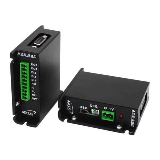
- Page 1 ACE-SXC Advanced Standalone Controller USB 2.0 Communication ACE-SXC Manual page 1 rev 2.05...
- Page 2 2.05 – 5 Release Firmware Compatibility: V420BL † †If your module’s firmware version number is less than the listed value, contact Arcus for the appropriate documentation. Arcus reserves the right to change the firmware without notice. ACE-SXC Manual page 2 rev 2.05...
-
Page 3: Table Of Contents
) ..................8 OWER ONNECTOR 4.2. DB9 C ........................8 ONNECTOR 4.3. 10-P DIO C (3.81 ) ..................9 ONNECTOR 4.4. ACE-SXC I ..................... 10 NTERFACE IRCUIT 4.5. P ........................11 OWER NPUT 4.6. P ................12 ULSE IRECTION AND... - Page 4 10.2.7. Standalone Example Program 7 – Multi Thread ............51 10.2.8. Standalone Example Program 8 – Multi Thread ............52 A: SPEED SETTINGS ........................53 A.1 A .................. 53 CCELERATION ECELERATION ANGE A.2 A – P ..........53 CCELERATION ECELERATION ANGE OSITIONAL ACE-SXC Manual page 4 rev 2.05...
-
Page 5: Introduction
1. Introduction ACE-SXC is a stepper controller motion product. Communication to the ACE-SXC can be established over USB. It is also possible to download a standalone program to the device and have it run independent of a host. Windows and Linux drivers, as well as a sample source code, are available to aid you in your software development. -
Page 6: Electrical And Thermal Specifications
Digital Input Forward Diode Current Digital Output Collector Voltage Digital Output Source Current Alarm Input Operating Temperature °C Storage Temperature +150 °C Table 2.0 The supply current should match the driver current setting. Based on component ratings. ACE-SXC Manual page 6 rev 2.05... -
Page 7: Dimensions
3. Dimensions Figure 3.0 †All dimensions in inches ACE-SXC Manual page 7 rev 2.05... -
Page 8: Connections
4. Connections In order for ACE-SXC to operate, it must be supplied with +12VDC to +24VDC. Power pins as well as communication port pin outs are shown below. 4.1. 2-Pin Power Connector (5.08mm) Figure 4.0 Pin # Name In/Out Description... -
Page 9: 10-Pin Dio Connector
Not Connected OPTO Opto-supply input (+12 to +24VDC) Table 4.2 Mating Connector Description: 10 pin 0.15” (3.81mm) connector Mating Connector Manufacturer: On-Shore Mating Connector Manufacturer Part: †EDZ1550/10 † Other 3.81 compatible connectors can be used ACE-SXC Manual page 9 rev 2.05... -
Page 10: Ace-Sxc Interface Circuit
4.4. ACE-SXC Interface Circuit Figure 4.3 ACE-SXC Manual page 10 rev 2.05... -
Page 11: Power Input
For example, if a driver’s maximum allowed voltage is +24VDC and the ACE-SXC is powered by +48VDC, powering the driver through the DB9 connector will damage the driver. -
Page 12: Pulse, Direction And Enable Outputs
4.5 shows the detailed schematic for these outputs. Each output is capable of sinking up to 45mA of current. Figure 4.5 Figure 4.6 shows an example wiring diagram between the pulse, direction, and enable outputs on the ACE-SXC and the corresponding input on a typical stepper driver. Figure 4.6 ACE-SXC Manual page 12 rev 2.05... -
Page 13: Alarm Input
Figure 4.7 shows an example wiring of the alarm signal Figure 4.7 4.8. Digital Inputs, Limits, and Home Figure 4.8 shows the detailed schematic of the opto-isolated general purpose digital inputs, limits, and home. All opto-isolated inputs are NPN type. Figure 4.8 ACE-SXC Manual page 13 rev 2.05... -
Page 14: Digital Outputs
45mA. Take caution to select the appropriate external resistor so that the current does not exceed 45mA. When deactivated, the opto-isolator will break the connection between the digital output and the opto-supply. ACE-SXC Manual page 14 rev 2.05... -
Page 15: Communication Interface
All USB communication will be down using an ASCII command protocol. 5.1.1. Typical USB Setup The ACE-SXC can be connected to a PC directly via USB or through a USB hub. All USB cables should have a noise suppression choke to avoid communication loss or interruption. - Page 16 64 characters. BOOL fnPerformaxComFlush(IN HANDLE pHandle) Flushes the communication buffer on the PC as well as the USB controller. It is recommended to perform this operation right after the communication handle is opened. ACE-SXC Manual page 16 rev 2.05...
-
Page 17: Usb Communication Issues
This will allow the PC to differentiate between multiple controllers. In order to make this change to an ACE-SXC, first store the desired number using the DN command. Note that this value must be within the range [SXC00 –... -
Page 18: General Operation Overview
USB. Standalone commands are used when writing a standalone program onto the ACE-SXC. 6.1. Motion Profile By default, the ACE-SXC uses a trapezoidal velocity profile as shown in Figure 6.0. Figure 6.0 Once a typical move is issued, the axis will immediately start moving at the low speed setting and accelerate to the high speed. -
Page 19: Motor Position
6.2. Motor Position The ACE-SXC has a 32 bit signed step position counter. Range of the position counter is from –2,147,483,648 to 2,147,483,647. Motor position can be read using the ASCII command PX, which returns the pulse position. To manually set/get the position of the motor, use the PX=[value] command. -
Page 20: Positional Moves
Instead, an error response is returned. See table 9.1 for details on error responses. The ACE-SXC has three different homing routines. The syntax for the home command in ASCII and standalone mode can be found below. ACE-SXC Manual page 20 rev 2.05... -
Page 21: Mode 1: Home Input Only (High Speed Only)
A. Issuing the command starts the motor from low speed and accelerates to high speed in search of the home input. B. As soon as the home input is triggered, the position counter is reset to zero and the motor stops. ASCII H[+/-] Standalone HOMEX[+/-] ACE-SXC Manual page 21 rev 2.05... -
Page 22: Mode 2: Limit Only
C. The motor will start moving in the opposite direction. First accelerating to high speed, maintaining speed, and then decelerating. D. Once position counter has reached zero, the motor stops. L[+/-] ASCII Standalone LHOMEX[+/-] ACE-SXC Manual page 22 rev 2.05... -
Page 23: Mode 3: Home Input Only (High Speed And Low Speed)
The same is for negative limit while moving in the negative direction. Once the limit error is set, the status must be cleared (using the CLR command) in order to move again. ACE-SXC Manual page 23 rev 2.05... -
Page 24: Motor Status
(CLR command). Communication timeout counter alarm Table 6.1 Examples: When motor status value is 0, motor is idle and all input switches are off. When motor status value is 2, motor is in acceleration. ACE-SXC Manual page 24 rev 2.05... -
Page 25: Digital Inputs / Outputs / Configuration Button
CLR command to clear the error before issuing any more move commands. 6.10. Digital Inputs / Outputs / Configuration Button The ACE-SXC module comes with three digital inputs and two digital outputs. If the limit/alarm function is disabled, up to eight inputs can be used as general purpose inputs. -
Page 26: Configuration Button
Standalone 6.12. Communication Time-Out Watchdog ACE-SXC allows for the user to trigger an alarm if the master has not communicated with the device for a set period of time. When an alarm is triggered, bit 10 of the MST parameter is turned on. The time-out value is set by the TOC command. -
Page 27: Standalone Program Specification
6.13. Standalone Program Specification Standalone programming allows the controller to execute a user defined program that is stored in the internal memory of the ACE-SXC. The standalone program can be run independently of USB communication or while communication is still active. -
Page 28: Standalone Subroutines
[0-1274]. 6.13.4. Standalone Subroutines The ACE-SXC has the capabilities of using up to 32 separate subroutines. Subroutines are typically used to perform functions that are repeated throughout the operation of the standalone program. Note that subroutines can be shared by both standalone programs. -
Page 29: Standalone Run On Boot-Up
Conversely, in the example below, the variable V1 will not be set until the motion has been completed. V1 will only be set once the controller is idle. X1000 ;* Move to position 1000 WAITX ;* Wait for the move to complete V1=100 ACE-SXC Manual page 29 rev 2.05... -
Page 30: Storing To Flash
Stepper driver parameters Time-out counter reset value Note that on boot-up, V1-V25 are reset to V26-V50 value 0 Table 6.9 Note: When a standalone program is downloaded, the program is immediately written to flash memory. ACE-SXC Manual page 30 rev 2.05... -
Page 31: Software Overview
Startup the ACE-SXC GUI program and you will see the following screen in Figure 7.0. This will allow the user to select from all the ACE-SXC devices currently connected to the USB network. To choose a particular device, select it and then press OK. -
Page 32: Main Control Screen
7.1. Main Control Screen The Main Control Screen provides accessibility to all the available function on the ACE-SXC. All features can be tested and verified. Figure 7.1 7.1.1. Status Figure 7.2 1. Position – Display of the current motor position value. Reset Position button is used to reset the counter. -
Page 33: Control
9. HL+/- – Low speed homing in the plus or minus direction. 10. L+/- – Limit homing in the plus or minus direction. 11. ISTOP – Immediate stop without deceleration. 12. RSTOP – Stop with deceleration. 7.1.3. Digital Input / Output / Enable Figure 7.4 ACE-SXC Manual page 33 rev 2.05... -
Page 34: Configuration
When the DMX-K-DRV button is selected, the DMX-K-DRV configuration dialog box is opened. From this dialog box, settings for DMX-K-DRV can be uploaded or downloaded. Note that the Temperature (showing the current driver temperature as detected) and Version are read-only. ACE-SXC Manual page 34 rev 2.05... - Page 35 Figure 7.7 The driver settings can be stored on ACE-SXC so that the parameter values can be used by the configuration button. Click the Close button to download the parameters to the ACE-SXC. To store the downloaded parameters permanently to the ACE-SXC controller, make sure to store to flash before powering down the controller.
-
Page 36: Program File Control
The driver settings can be stored on ACE-SXC so that the parameter values can be used by the configuration button. Click the Close button to download the parameters to the ACE-SXC. To store the downloaded parameters permanently to the ACE-SXC controller, make sure to store to flash before powering down the controller. -
Page 37: Standalone Program Control
Figure 7.12 1. Compile – Compile the standalone program. 2. Download – Download the compiled program. 3. Upload – Upload the standalone program from the controller. 4. View – View the low level compiled program. ACE-SXC Manual page 37 rev 2.05... -
Page 38: Setup
7.1.9. Setup Figure 7.13 1. Polarity – Change the polarity of the inputs and outputs of the ACE-SXC. 2. DOBOOT/EOBOOT – Change the boot up configuration of the enable and digital outputs. 3. Auto Run – Run standalone programs on boot up. -
Page 39: Terminal
Figure 7.14 Interactive ASCII commands can be sent and replies can be received. See interactive commands for details. 7.1.11. Variable Status Figure 7.15 1. Command: – To write to a variable, use V[1-50] = [value]. ACE-SXC Manual page 39 rev 2.05... -
Page 40: Dmx And Ace Configuration
Method #2 uses the configuration button on the ACE-SXC controller to download the driver parameters. On the ACE-SXC controller, the driver type needs to be stored to flash so that when the button configuration is used, the correct driver configuration is performed. - Page 41 Once the correct driver type is selected and the driver parameter values are stored to flash memory, driver parameters can be downloaded from ACE-SXC to DMX-K-DRV without the use of Windows PC using the configuration button on the ACE-SXC. To configure the driver through the configuration button, follow the steps below.
-
Page 42: Ascii Language Specification
ASCII commands and are not analogous to standalone commands. Refer to section 10 for details regarding standalone commands. ACE-SXC language is case sensitive. All commands should be in upper case letters. Invalid commands are returned with a “?”. Always check for the proper reply when a command is sent. - Page 43 Bit 0 – Standalone program 0 0 – Do NOT run standalone program on boot up 1 – Run standalone program on boot up Bit 1 – Standalone program 1 SR[0-1]=[Value] Control standalone program: 0 – Stop standalone program ACE-SXC Manual page 43 rev 2.05...
-
Page 44: Error Codes
100000, target move must be between 362143 and -162143 Table 9.0 9.2. Error Codes If an ASCII command cannot be processed by the ACE-SXC, the controller will reply with an error code. See below for possible error responses: Error Code Description... -
Page 45: Standalone Language Specification
WAITX ;wait for home move specified direction. HOMEX[+/-] Home the motor using the home input HOMEX- ;negative home at high speed in specified direction. WAITX ;wait for home move ACE-SXC Manual page 45 rev 2.05... - Page 46 V4=DO ;SET V4 TO DO [*] Multiplication V5=~EO ;SET V5 TO NOT EO [/] Division [%] Modulus [>>] Bit shift right [<<] Bit shift left [&] Bitwise AND [|] Bitwise OR [~] Bitwise NOT ACE-SXC Manual page 46 rev 2.05...
-
Page 47: Example Standalone Programs
EO=1 ;* Enable the motor power WHILE 1=1 ;* Forever loop X1000 ;* Move to zero WAITX ;* Wait for move to complete ;* Move to 1000 ENDWHILE ;* Go back to WHILE statement ACE-SXC Manual page 47 rev 2.05... -
Page 48: Standalone Example Program 3 - Single Thread
;* If digital input 1 is on, execute the statements X1000 ;* Move to zero WAITX ;* Wait for move to complete ;* Move to 1000 ENDIF ENDWHILE ;* Go back to WHILE statement ACE-SXC Manual page 48 rev 2.05... -
Page 49: Standalone Example Program 5 - Single Thread
SUB 1 ;* Move to V1 target position V1=V1+1000 ;* Increment V1 by 1000 WHILE DI1=1 ;* Wait until the DI1 is turned off so that ENDWHILE ;* 1000 increment is not continuously done ENDSUB ACE-SXC Manual page 49 rev 2.05... -
Page 50: Standalone Example Program 6 - Single Thread
;* Home the motor in negative direction ENDIF V1=MSTX ;* Store the motor status to variable 1 V2=V1&7 ;* Get first 3 bits IF V2!=0 DO1=1 ELSE DO1=0 ENDIF ENDWHILE ;* Go back to WHILE statement ACE-SXC Manual page 50 rev 2.05... -
Page 51: Standalone Example Program 7 - Multi Thread
;* Stop Program 1 ELSE ;* If digital input 1 is not triggered SR0=1 ;* Run Program 1 ENDIF ;* End if statements ENDWHILE ;* Go back to WHILE statement ;* End Program 1 ACE-SXC Manual page 51 rev 2.05... -
Page 52: Standalone Example Program 8 - Multi Thread
;* Abort the motor DO=0 ;* Set DO=0 DELAY=3000;* Delay 3 seconds SR0=1 ;* Turn program 0 back on DO=1 ;* Set DO=1 ENDIF ENDWHILE ;* Go back to WHILE statement ;* End Program 1 ACE-SXC Manual page 52 rev 2.05... -
Page 53: A: Speed Settings
((400,000 – 1000) / 18,000) x 1000 ms = 22166 ms (22.17 sec) A.2 Acceleration/Deceleration Range – Positional Move When dealing with positional moves, the controller automatically calculates the appropriate acceleration and deceleration based on the following rules. ACE-SXC Manual page 53 rev 2.05... - Page 54 L/2, the acceleration value is used for both ramp up and ramp down. This is regardless of the EDEC setting. 3. Triangle Profile: If either (1) or (2) occur, the velocity profile becomes a triangle. Maximum speed is reached at L/2. ACE-SXC Manual page 54 rev 2.05...
- Page 55 Contact Information Arcus Technology, Inc. 3159 Independence Drive Livermore, CA 94551 925-373-8800 www.arcus-technology.com The information in this document is believed to be accurate at the time of publication but is subject to change without notice. ACE-SXC Manual page 55 rev 2.05...
Need help?
Do you have a question about the ACE-SXC and is the answer not in the manual?
Questions and answers