
Subscribe to Our Youtube Channel
Related Manuals for Arcus ACE-SXC


Summary of Contents for Arcus ACE-SXC
- Page 1 ACE-SXC Advanced Stand-Alone Controller USB 2.0 communication ACE-SXC Manual page 1 rev2.02...
- Page 2 2.02 – 3 release Firmware Compatibility: V419BL † †If your module’s firmware version number is less than the listed value, contact Arcus for the appropriate documentation. Arcus reserves the right to change the firmware without notice. ACE-SXC Manual page 2 rev2.02...
-
Page 3: Table Of Contents
4. Connections........................9 DB9 Connector ......................10 2-Pin Connector (5.08mm) ................... 10 10-Pin Connector (3.81mm) ..................10 ACE-SXC Interface Circuit ..................12 Power Input ........................13 Pulse, Direction and Enable Outputs ................14 Alarm Input ........................14 Limits, Home and Digital Inputs .................. 15 Digital Outputs ...................... - Page 4 ELSE ..........................48 ELSEIF ......................... 49 END ..........................50 ENDIF ........................... 50 ENDSUB........................50 ENDWHILE ......................... 51 EO ..........................51 GOSUB ......................... 51 HLHOMEX[+ or -] ....................... 52 HOMEX[+ or -] ......................52 HSPD ..........................53 ACE-SXC Manual page 4 rev2.02...
- Page 5 Standalone Example Program 4 – Single Thread ............62 Standalone Example Program 5 – Single Thread ............62 Standalone Example Program 6 – Single Thread ............63 Standalone Example Program 7 – Multi Thread............64 Standalone Example Program 8 – Multi Thread............65 ACE-SXC Manual page 5 rev2.02...
-
Page 6: Introduction
1. Introduction ACE-SXC is a stepper controller motion product. Communication to the ACE-SXC can be established over USB. It is also possible to download a stand-alone program to the device and have it run independent of a host. Windows and Linux drivers as well as sample source code are available to aid you in your software development. -
Page 7: Electrical And Thermal Specifications
† Includes limit, home and latch Digital Outputs Type: Opto-isolated open-collector PNP outputs +24 VDC Max voltage at emitter: †45 mA Max source current at 24VDC † A current limiting resistor is required Alarm Input Type: +0 to +5VDC Voltage: ACE-SXC Manual page 7 rev2.02... -
Page 8: Dimensions
3. Dimensions Figure 3.0 †All dimensions in inches ACE-SXC Manual page 8 rev2.02... -
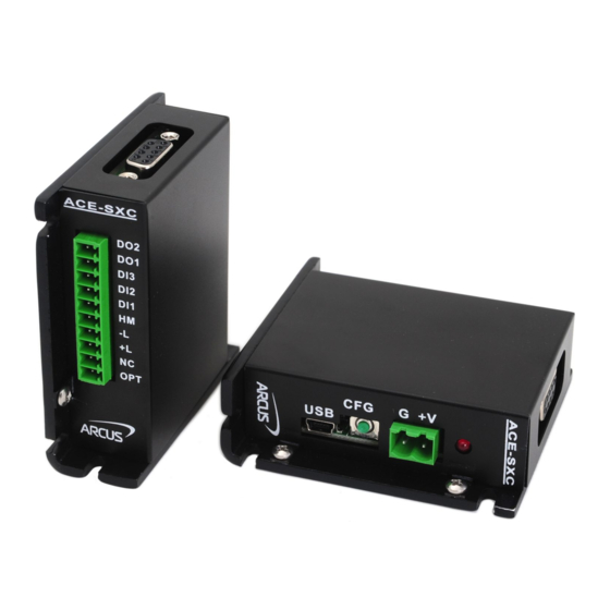
Page 9: Connections
4. Connections Figure 4.0 ACE-SXC Manual page 9 rev2.02... -
Page 10: Db9 Connector
† Other 5.08mm compatible connectors can be used. 10-Pin Connector (3.81mm) Pin # In/Out Name Description Digital Output 1 Digital Output 2 Digital Input 3 Digital Input 2 Digital Input 1 HOME Home Input -LIM Minus Limit Input +LIM Plus Limit Input ACE-SXC Manual page 10 rev2.02... - Page 11 Reserved. Do not connect OPTO Opto-supply input (+12 to +24VDC) Table 4.3 Mating Connector Description: 10 pin 0.15” (3.81mm) connector Mating Connector Manufacturer: On-Shore Mating Connector Manufacturer Part: †EDZ1550/10 † Other 3.81 compatible connectors can be used. ACE-SXC Manual page 11 rev2.02...
-
Page 12: Ace-Sxc Interface Circuit
ACE-SXC Interface Circuit Figure 4.4 ACE-SXC Manual page 12 rev2.02... -
Page 13: Power Input
Power Input Figure 4.5 shows that the power and ground signals that are supplied to ACE-SXC through the 2 pin connector are also available through the DB9 pin connector. Regulated Supply Voltage Range: +12 to 48 VDC Recommended Current for power supply: †200 mA... -
Page 14: Pulse, Direction And Enable Outputs
Figure 4.6 shows an example of the pulse, direction and enable connections to a driver. Figure 4.6 Alarm Input Alarm input is a TTL compatible input using the 74LS07. Figure 4.7 shows an example wiring of the alarm signal Figure 4.7 ACE-SXC Manual page 14 rev2.02... -
Page 15: Limits, Home And Digital Inputs
Figure 4.8 shows an example wiring of the home, limit and digital inputs. Figure 4.8 Digital inputs are active high. Digital Outputs Figure 4.9 shows an example wiring of the digital outputs. Figure 4.9 Digital outputs are active low. ACE-SXC Manual page 15 rev2.02... -
Page 16: Getting Started
5. Getting Started Typical Setup PC-Controlled Figure 5.1 Stand-Alone Operation Figure 5.2 ACE-SXC Manual page 16 rev2.02... -
Page 17: Windows Gui
Windows GUI ACE-SXC comes with Windows GUI program to test, program, compile, download, and debug the controller. The GUI program can also be used to configure driver settings of DMX-K-DRV, DMX-A2-DRV, and ACE-SDX. Make sure that the USB driver is installed properly before running the controller. -
Page 18: Status
4. Mode – Display of the move mode of the controller. Possible values are: ABS – Absolute position movement INC – Incremental position movement 5. Limit and Home and Alarm Input Status – Display of limits,home and alarm input status. ACE-SXC Manual page 18 rev2.02... -
Page 19: Axis Control
9. HL+/- - Low speed homing in the plus of minus direction 10. L+/- - Limit homing in the plus or minus direction 11. ISTOP – Immediate stop without deceleration 12. RSTOP – Stop with deceleration ACE-SXC Manual page 19 rev2.02... -
Page 20: Di Status/Do Status/Enable
2. DMX-K-DRV Configuration using Windows GUI – DMX-K-DRV can be configured from the GUI by selecting the DMX-K-DRV button. When the DMX-K-DRV button is selected the DMX-K-DRV configuration dialog box is opened. From this dialog box, settings for ACE-SXC Manual page 20 rev2.02... - Page 21 Version are read-only. Figure 5.8 The driver settings can be stored on ACE-SXC so that the parameter values can be used by the configuration button. Click the Close button to download the parameters to the ACE-SXC. To store the downloaded parameters permanently to the ACE-SXC controller, make sure to store to flash before powering down the controller.
-
Page 22: Terminal
Figure 5.9 The driver settings can be stored on ACE-SXC so that the parameter values can be used by the configuration button. Click the Close button to download the parameters to the ACE-SXC. To store the downloaded parameters permanently to the ACE-SXC controller, make sure to store to flash before powering down the controller. -
Page 23: Setup
F. Setup Figure 5.11 1. Polarity - Change the polarity of the inputs and outputs of the ACE-SXC 2. DOBOOT/EOBOOT - Change the boot up configuration of the enable and digital outputs 3. Auto Run - Run standalone programs on boot up. -
Page 24: Standalone Program File Management
1. Write the standalone program in the Program Editor 2. Clear Code Space – Use this button to remove the current standalone program that is currently stored on the ACE-SXC. 3. Use this button to open a larger and easier to manage program editor. -
Page 25: Standalone Program Compile/Download/Upload/View
Errored – program is in error status 2. Program Index – display of low level program index. This is the index of the low level program index. 3. X-Thread – Open the Program Control for standalone multi-thread operation. ACE-SXC Manual page 25 rev2.02... -
Page 26: Variable Status
4. Program Control – Program can be RUN, STOP, PAUSED, and CONTINUED. K. Variable Status View the status of variables 1-50. Note that this window is read-only. Figure 5.16 1. Command line – To write to variable, use V[1-50] = [value] syntax. ACE-SXC Manual page 26 rev2.02... -
Page 27: Motion Control Overview
Acceleration range is from 10 msec to 1000 msec. Position Counter ACE-SXC has a 32 bit signed position counter. Range of the position counter is from –2,147,483,648 to 2,147,483,647. Get the current position by using the PX command. Note: If a motion command is sent while the controller is already moving, the command is not processed. -
Page 28: Homing
MODE command to read the current move mode. Homing Home search sequence involves moving the motor towards the home or limit switches and then stopping when the relevant input is detected. The ACE-SXC has three different homing routines: Home Input Only (High speed only) Use the H+/H- command. -
Page 29: Home Input Only (High Speed And Low Speed)
E. The home input is triggered again, the position counter is reset to zero and the motor immediately stops. Limit Only Use the L+/L- command. Figure 6.4 shows the homing routine. Figure 6.4 ACE-SXC Manual page 29 rev2.02... -
Page 30: Jog Move
Note: The DL command controls both the limit switch function as well as the alarm input function. Limit inputs are active high. ACE-SXC Manual page 30 rev2.02... -
Page 31: Alarm Input Function
Alarm error. This bit is latched when the alarm input is triggered while motion is in progress. This error must be cleared before issuing any subsequent move commands (CLR command). Communication timeout counter alarm Table 6.0 ACE-SXC Manual page 31 rev2.02... -
Page 32: Digital Inputs
Digital Inputs ACE-SXC module comes with 3 digital inputs. If the limit/alarm function is disabled, up to 8 inputs can be used as general purpose inputs Read digital input status using the DI command. See description below: Digital input values can also be referenced one bit at a time by the DI[1-8] commands. -
Page 33: Motor Power
Table 6.3 Device Number ACE-SXC module provides the user with the ability to set the device number of a specific device. In order to make these changes, first store the desired number using the DN command. Please note that this value must be within the range [SXC01,SXC99]. -
Page 34: Communication Time-Out Feature (Watchdog)
Table 6.4 Communication Time-out Feature (Watchdog) ACE-SXC allows for the user to trigger an alarm if the master has not communicated with the device for a set period of time. When an alarm is triggered bit 10 of the MST parameter is turned on. -
Page 35: Storing To Flash
Stepper driver parameters Time-out counter reset value Note that on boot-up, V1-V25 are reset to V26-V50 value 0 Table 6.5 Note: When a standalone program is downloaded, the program is immediately written to flash memory. ACE-SXC Manual page 35 rev2.02... -
Page 36: Connecting To Dmx And Ace Drivers
7. Connecting to DMX and ACE Drivers Connecting DMX-K-DRV-11/17 Cable Accessory: CBL-DB_9M-DF11_10F-L1-G24-V1 Figure 7.1 Connecting to DMX-K-DRV-23 Cable Accessory: CBL-DB_9M-DF3_10-L1-G24-V1 Figure 7.2 ACE-SXC Manual page 36 rev2.02... -
Page 37: Connecting To Dmx-A2-Drv-17/23
Connecting to DMX-A2-DRV-17/23 Cable Accessory: CBL-DB_9M-DB_9F-L1-G24-V1 Figure 7.3 Connecting to ACE-SDX Cable Accessory: CBL-DB_9M-I_8F-L1-G24-V1 Figure 7.4 ACE-SXC Manual page 37 rev2.02... -
Page 38: Dmx And Ace Configuration
Method #2 uses the configuration button on the ACE-SXC controller to download the driver parameters. On the ACE-SXC controller, the driver type needs to be stored to flash so that when the button configuration is used, the correct driver configuration is performed. There are two types types for button configuration: 1) K-DRV and 2) A2-DRV/ACE-SDX. - Page 39 Once the correct driver type is selected and the driver parameter values are stored to flash memory,, driver parameters can be downloaded from ACE-SXC to DMX-K-DRV without the use of Windows PC using the configuration button on the ACE-SXC. To configure the driver through the configuration button, follow the steps below.
-
Page 40: Communication - Usb
9. Communication – USB ACE-SXC USB communication is USB 2.0 compliant. Communication between the PC and ACE-SXC is done using Windows compatible DLL API function calls as shown below. Windows programming language such as Visual BASIC, Visual C++, LABView, or any other programming language that can use DLL can be used to communicate with the Performax module. -
Page 41: Usb Communication Issues
2) USB Cable: Another source of USB communication issues may come from the USB cable. Confirm that the USB cable being used has a noise suppression choke. See photo below: Figure 9.1 ACE-SXC Manual page 41 rev2.02... -
Page 42: Ascii Language Specification
All the commands described in this section are interactive commands only. Refer to the “Standalone Language Specification” section for the stand-alone code API. ACE-SXC language is case sensitive. All command should be in capital letters. Invalid command is returned “?”. Always check for proper reply when command is sent. - Page 43 2 – Pause standalone program 3 – Continue standalone program Get program counter for standalone program [0-1274] STORE Store settings to flash Get communication time out parameter TOC=[Value] Set communication time-out parameter V[1-50] Read variables 1-50 32-bit number ACE-SXC Manual page 43 rev2.02...
-
Page 44: Error Codes
100000, target move must be between 362143 and -162143 Table 10.1 Error Codes If an ASCII command cannot be processed by the ACE-SXC, the controller will reply with an error code. See below for possible error responses: Error Code Description... -
Page 45: Standalone Language Specification
Command: Changes all move commands to absolute mode. Syntax: Examples: ;***Change to absolute mode PX=0 ;***Change position to 0 X1000 ;***Move X axis to position 1000 WAITX X3000 ;***Move X axis to position 3000 WAITX ACE-SXC Manual page 45 rev2.02... -
Page 46: Acc
;***Jogs axis to positive direction DELAY=10000 ;***Wait 10 second ABORTX ;***Stop axis Description: Read: Gets the digital input value. ACE-SXC has 8 digital inputs. Digital inputs are active high Syntax: Read: [variable] = DI Conditional: IF DI=[variable] ENDIF IF DI=[value]... - Page 47 DI[1-8] Description: Read: Gets the digital input value. ACE-SXC has 8 digital inputs. Digital inputs are active high Syntax: Read: [variable] = DI[1-8] Conditional: IF DI[1-8]=[variable] ENDIF IF DI[1-8]=[0 or 1] ENDIF Examples: IF DI1=0 DO=1 ;***If digital input 1 is triggered, set DO=1...
-
Page 48: Eclearx
DO[1-2] Description: Read: Gets the individual digital output value Write: Sets the individual digital output value ACE-SXC has 2 digital outputs. Digital outputs are active low. Syntax: Read: [variable] = DO[1-2] Write: DO[1-2] = [0 or 1] DO[1-2] = [variable]... -
Page 49: Elseif
Greater than < Less than >= Greater than or equal to <= Less than or equal to Not Equal to Examples: IF V1=1 X1000 WAITX ELSEIF V1=2 X2000 WAITX ELSEIF V1=3 X3000 WAITX ELSE WAITX ENDIF ACE-SXC Manual page 49 rev2.02... -
Page 50: End
Examples: IF V1=1 X1000 WAITX ENDIF ENDSUB Description: Indicates end of subroutine When ENDSUB is reached, the program returns to the previously called subroutine. Syntax: ENDSUB Examples: GOSUB 1 SUB 1 WAITX X1000 WAITX ENDSUB ACE-SXC Manual page 50 rev2.02... -
Page 51: Endwhile
GOSUB Description: Perform go to subroutine operation Subroutine range is from 0 to 31. Note: Subroutine definitions should be written AFTER the END statement. Subroutine 31 is reserved for error handling. Syntax: GOSUB [subroutine number] ACE-SXC Manual page 51 rev2.02... -
Page 52: Hlhomex[+ Or -]
HLHOMEX+ ;***Homes the motor at low speed in the positive direction WAITX HOMEX[+ or -] Description: Command: Perform homing using current high speed, low speed, and acceleration. Syntax: HOMEX[+ or -] Examples: HOMEX+ ;***Homes axis in positive direction WAITX ACE-SXC Manual page 52 rev2.02... -
Page 53: Hspd
[Comparison] can be any of the following Equal to > Greater than < Less than >= Greater than or equal to <= Less than or equal to Not Equal to Examples: IF V1=1 X1000 WAITX ENDIF ACE-SXC Manual page 53 rev2.02... -
Page 54: Inc
;***Jogs axis in negative direction STOPX WAITX LHOMEX[+ or -] Description: Command: Perform homing using current high speed, low speed, and acceleration. Syntax: LHOMEX[+ or -] Examples: LHOMEX+ ;***Limit homes axis in positive direction WAITX ACE-SXC Manual page 54 rev2.02... -
Page 55: Lspd
LSPD=V1 ;***Sets the start low speed to variable 1 value of 500 MSTX Description: Read: Get motor status Syntax: Read: [variable]=MSTX Conditional: IF MSTX=[variable] ENDIF IF MSTX=[value] ENDIF Examples: IF MSTX=0 DO=3 ELSE DO=0 ENDIF ACE-SXC Manual page 55 rev2.02... -
Page 56: Stopx
Description: Command: Stop all axes if in motion with deceleration. Previous acceleration value is used for deceleration. Syntax: STOPX Examples: JOGX+ ;***Jogs axis to positive direction DELAY=1000 ;***Wait 1 second STOPX ;***Stop with deceleration WAITX ACE-SXC Manual page 56 rev2.02... -
Page 57: Store
DELAY=1000 ;***Wait 1 second STORE ;***Store V40 to non-volatile flas Description: Indicates start of subroutine Syntax: SUB [subroutine number] [Subroutine Number] range is 0 to 31 Examples: GOSUB 1 SUB 1 WAITX X1000 WAITX ENDSUB ACE-SXC Manual page 57 rev2.02... -
Page 58: Toc
TOC=[long value] Examples: TOC=10000 ;***Sets time-out parameter to 10 seconds V[1-50] Description: Assign to variable. ACE-SXC has 100 variables [V1-V50] Syntax: V[Variable Number] = [Argument] V[Variable Number] = [Argument1][Operation][Argument2] Special case for BIT NOT: V[Variable Number] = ~[Argument] [Argument] can be any of the following:... -
Page 59: Waitx
> Greater than < Less than >= Greater than or equal to <= Less than or equal to Not Equal to Examples: WHILE V1=1 ;***While V1 is 1 continue to loop WAITX X1000 WAITX ENDWHILE ACE-SXC Manual page 59 rev2.02... - Page 60 Perform X axis move to target location Syntax: X[value] X[variable] Examples: ;***Absolute move mode X10000 ;***Move to position 10000 WAITX V10 = 1200 ;***Set variable 10 value to 1200 XV10 ;***Move axis to variable 10 value WAITX ACE-SXC Manual page 60 rev2.02...
-
Page 61: Example Standalone Programs
;* Loop while variable 1 is less than 10 X1000 ;* Move to zero WAITX ;*Wait for X-axis move to complete ;* Move to 1000 V1=V1+1 ;* Increment variable 1 ENDWHILE ;* Go back to WHILE statement ACE-SXC Manual page 61 rev2.02... -
Page 62: Standalone Example Program 4 - Single Thread
SUB 1 ;* Move to V1 target position V1=V1+1000 ;* Increment V1 by 1000 WHILE DI1=1 ;* Wait until the DI1 is turned off so that ENDWHILE ;* 1000 increment is not continuously done ENDSUB ACE-SXC Manual page 62 rev2.02... -
Page 63: Standalone Example Program 6 - Single Thread
;* Home the motor in negative direction ENDIF V1=MSTX ;* Store the motor status to variable 1 V2=V1&7 ;* Get first 3 bits IF V2!=0 DO1=1 ELSE DO1=0 ENDIF ENDWHILE ;* Go back to WHILE statement ACE-SXC Manual page 63 rev2.02... -
Page 64: Standalone Example Program 7 - Multi Thread
SR0=0 ;* Stop Program 1 ELSE ;* If digital input 1 is not triggered SR0=1 ;* Run Program 1 ENDIF ;* End if statements ENDWHILE ;* Go back to WHILE statement ;* End Program 1 ACE-SXC Manual page 64 rev2.02... -
Page 65: Standalone Example Program 8 - Multi Thread
;* Abort the motor DO=0 ;* Set DO=0 DELAY=3000;* Delay 3 seconds SR0=1 ;* Turn program 0 back on DO=1 ;* Set DO=1 ENDIF ENDWHILE ;* Go back to WHILE statement ;* End Program 1 ACE-SXC Manual page 65 rev2.02... - Page 66 Contact Information Arcus Technology, Inc. 3159 Independence Drive Livermore, CA 94551 925-373-8800 www.arcustechnology.com The information in this document is believed to be accurate at the time of publication but is subject to change without notice. ACE-SXC Manual page 66 rev2.02...
Need help?
Do you have a question about the ACE-SXC and is the answer not in the manual?
Questions and answers