
Subscribe to Our Youtube Channel
Related Manuals for Arcus ACE-SXC


Summary of Contents for Arcus ACE-SXC
- Page 1 ACE-SXC Single Axis Step Motor Controller with USB 2.0 Communication ACE-SXC Manual page 1 rev 1.30...
- Page 2 ARCUS. ARCUS makes no representations or warranties regarding the content of this document. We reserve the right to revise this document any time without notice and obligation.
-
Page 3: Table Of Contents
Connecting ACE-SXC to ACE-SDX................17 8. DriveMax Configuration....................18 Configuration Method #1 – Using Windows PC............19 Configuration Method #2 – Using the Configuration Button........19 9. ACE-SXC GUI Windows Program ................20 Motor Status........................21 Motor Control ....................... 22 DI Status/DO Status/Enable..................23 Configuration ........................ - Page 4 Miscellaneous Commands .................... 39 Standalone Example Program 1..................40 Standalone Example Program 2..................40 Standalone Example Program 3..................40 Standalone Example Program 4..................41 Standalone Example Program 5..................41 Standalone Example Program 6..................42 ACE-SXC Manual page 4 rev 1.30...
-
Page 5: Introduction
1. Introduction ACE-SXC is a single axis step motor controller with following features: USB 2.0 Communication PC based control through USB 2.0 Standalone Control with BASIC-like programming language 12-48VDC voltage input Pulse/Dir differential signal output 400K maximum pulse rate output... -
Page 6: Dimensions
3. Dimensions ACE-SXC Manual page 6 rev 1.30... -
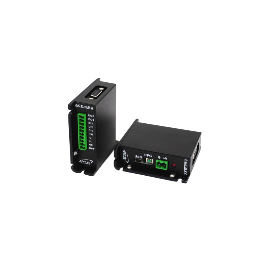
Page 7: Connectors
4. Connectors DB9 Pinout Name Type PUL+ DIR+ PUL- DIR- ACE-SXC Manual page 7 rev 1.30... -
Page 8: Electrical Specifications
5. Electrical Specifications Internal Interface Circuit Overview ACE-SXC Manual page 8 rev 1.30... -
Page 9: Power Input
DB-9 additional current is required to power the driver.) Power and ground signals that are supplied to ACE-SXC through 2 pin connector are also available through the DB9 pin connector. Important Note: If the driver is powered through the DB9 connector, make sure that the voltage of the power supply does not go over the maximum rated power supply voltage of the driver. -
Page 10: Pulse And Direction Outputs
Pulse and Direction Outputs Pulse and Direction Outputs are differential outputs using 75LS191. An example of connection to differential pulse/dir input driver is shown below: An example of connection to single-ended pulse/dir input driver is shown below: ACE-SXC Manual page 10 rev 1.30... -
Page 11: Enable Output
Enable Output is an open collector output using 74LS07. An example of enable circuit connection to a driver is shown below. Alarm Input Alarm input is a TTL compatible input using the 74LS07. An example of Alarm circuit is shown below. ACE-SXC Manual page 11 rev 1.30... -
Page 12: Limits, Home And Digital Inputs
Digital Outputs: Type: Opto-isolated open-emitter transistor output 50 mA Maximum emitter current: Operating Temperature Electronic components used in ACE-SXC have maximum ambient operating temperature of 85 degree Celsius. ACE-SXC Manual page 12 rev 1.30... -
Page 13: Motion Control Overview
10 msec to 1000 msec. Pulse output rate supported is from 100 to 400K pulses/second. Position Counter ACE-SXC has 32 bit signed position counter. Range of the position counter is from –2,147,483,648 to 2,147,483,647. Target Move Target move, also known as absolute move, is used to move the motor to the desired position from the current position. -
Page 14: Jog Move
Limit switch function can also be disabled. By disabling the limit switch function, the limits switches can be used as general purpose inputs. When limit function is disabled, digital input assignments are: DI5 for –Limit and DI7 for +Limit. ACE-SXC Manual page 14 rev 1.30... -
Page 15: Motor Status
This error must be cleared before issuing any subsequent move commands. Alarm error. This bit is latched when the alarm input is triggered while motion is in progress. This error must be cleared before issuing any subsequent move commands. ACE-SXC Manual page 15 rev 1.30... -
Page 16: Connecting To Dmx-K-Drv, Dmx-A2-Drv, And Ace-Sdx
7. Connecting to DMX-K-DRV, DMX-A2-DRV, and ACE-SDX Connecting ACE-SXC to DMX-K-DRV-11/17 Connecting ACE-SXC to DMX-K-DRV-23 ACE-SXC Manual page 16 rev 1.30... -
Page 17: Connecting Ace-Sxc To Dmx-A2-Drv-17/23
Connecting ACE-SXC to DMX-A2-DRV-17/23 Connecting ACE-SXC to ACE-SDX ACE-SXC Manual page 17 rev 1.30... -
Page 18: Drivemax Configuration
8. DriveMax Configuration ACE-SXC can be used to configure the driver settings for the following products. DMX-K-DRV-11/17/23 DMX-A2-DRV-17/23 ACE-SDX ACE-SXC uses patent pending Dynamic Configuration method of reading and writing of the driver setting through control lines: PULSE/DIR/ENABLE/ALARM. There are two ways to configure the DMX-K/DMX-A2/ACE-SDX using ACE-SXC. -
Page 19: Configuration Method #1 - Using Windows Pc
ACE-SXC controller. On the ACE-SXC controller, driver type needs to be stored on the flash so that when the button configuration is used, correct driver configuration is done. There are two types of driver type for button configuration: 1) K-DRV and 2) A2-DRV/ACE-SDX. -
Page 20: Ace-Sxc Gui Windows Program
Important Note: In order to communicate with ACE-SXC through USB, proper driver must be installed first. Before connecting the ACE-SXC device or running any program, please go to the Arcus web site and download the USB driver installation instruction and run the USB Driver Installation Program. -
Page 21: Motor Status
+LIM ERROR – plus limit error occurred C. Clear Error – Clear Error button is used to clear the Limit error status. D. Limit and Home and Alarm Input Status – Display of limits and home and alarm input status. ACE-SXC Manual page 21 rev 1.30... -
Page 22: Motor Control
I. JOG+ - Jog to plus direction J. RSTOP – Stop with deceleration K. ISTOP – Immediate stop without deceleration L. HOME- - Homing in minus direction M. HOME+ - Homing in plus direction ACE-SXC Manual page 22 rev 1.30... -
Page 23: Di Status/Do Status/Enable
D. Enable Output Status – Enable output status. Enable output can be toggled by clicking on the circle. When the enable is on, the driver is enabled and the motor is energized. ACE-SXC Manual page 23 rev 1.30... -
Page 24: Configuration
ACE-SXC product. Firmware version loaded on the ACE-SXC is shown. Device name can be changed so that multiple ACE-SXC can be connected on the USB. When entering the new Device Name, make sure to enter in the format of SXCXX where XX ranges from 00 to 99. - Page 25 Note that Temperature (showing the current driver temperature as detected) and Version can only be uploaded. The driver settings can be stored on ACE-SXC so that the parameter values can be used by the configuration button. To save to ACE-SXC, select Save and Close button which will download the parameters to the ACE-SXC.
- Page 26 Note that Temperature (showing the current driver temperature as detected) and Version can only be uploaded. The driver settings can be stored on ACE-SXC so that the parameter values can be used by the configuration button. To save to ACE-SXC, select Save and Close button which will download the parameters to the ACE-SXC.
-
Page 27: Program Control
C. Program Control – Program can be RUN, STOP, PAUSED, and CONTINUED. Program Text Interactive terminal commands can be sent and replies can be received. See interactive commands for details of the interactive commands. ACE-SXC Manual page 27 rev 1.30... -
Page 28: Program Text
D. Upload – Program in the controller is uploaded and decompiled to high level. E. View – Compiled low-level program can be viewed. F. Close – ACE-SXC GUI program is closed. G. Open – Open program H. Save – Save program I. -
Page 29: Control Method Overview
10. Control Method Overview ACE-SXC is a single axis step motor controller with USB 2.0 communication. ACE- SXC can work in two modes as shown below. PC based Control - As slave to a Windows PC through USB 2.0 communication as shown below. -
Page 30: Standalone Control
IO. Digital IO can be used to perform operations such as trigger a sequence of motions or report the motion completion and error status. Standalone program is written using a BASIC-like language using the ACE-SXC GUI Windows program that can be downloaded from the Arcus website. -
Page 31: Pc Based Control
PerformaxComGetNumDevices (long *Num) int PerformaxComGetProductString (long DeviceNum, char *DeviceString, 0) Step B – Open Device Once the ACE-SXC device is found, it can be opened by the following API function. int PerformaxComOpen(long DeviceNum, Long *Handle) Step C – Communicate Once the ACE-SXC device is opened, commands can be sent and reply can be received by following API function. -
Page 32: Interactive Commands
Bit 6 – Minus Limit Error Bit 7 – Plus Limit Error Returns Polarity 0 to 3 Bit 0 – Direction Polarity Bit 1 – Limit Polarity (Valid when Disable Limit is off) POL=[value] 0 to 3 Sets polarity ACE-SXC Manual page 32 rev 1.30... - Page 33 Return variable value. Var # from 1 to 49 -2147483648 2147483647 V[var#]=[value] -2147483648 Sets variable value. Var # from 1 to 49 2147483647 X[Value] Maximum delta Performs absolute move from current position to target = 262,143 ACE-SXC Manual page 33 rev 1.30...
-
Page 34: Standalone Control
Standalone program is written using the ACE-SXC GUI Windows program. Standalone program is then compiled, and downloaded to the ACE-SXC. With ACE-SXC, a standalone program can be downloaded and have it automatically run at the power up. ACE-SXC supports only one task program running. - Page 35 1) Each program must have an END to indicate the end of the program. 2) Declaration of the subroutine must be done after the END statement. 3) Comments in the program are started with character. ACE-SXC Manual page 35 rev 1.30...
-
Page 36: Standalone Programming Language
Move to absolute target position. Maximum difference between current and target position to target = 262,143 position must be equal or less than 262,143. Example: X1200, XV1 [value] can be either a numerical value or a variable. ACE-SXC Manual page 36 rev 1.30... -
Page 37: Conditional And Program Flow Control Commands
LOOPWHILE conditional statement. Must be used with REPEAT statement. [Arg1][Comp][Arg2] [Arg1][Arg2] can be any of the following [Comp] can be any of the following Numerical Value Variable < <= > DI[bit] >= DO[bit] MSTX ACE-SXC Manual page 37 rev 1.30... -
Page 38: Variable Commands
Variable Operation. Operation can be any of the following: of the following: + Addition Numerical Value - Subtraction DI[bit] * Multiplication DO[bit] / Division >> Bit shift Left << Bit Shift Right MSTX & Bit AND V[var#] | Bit OR ACE-SXC Manual page 38 rev 1.30... -
Page 39: Miscellaneous Commands
Value Description DELAY=[value] 1 to 1000 Performs delay. Each unit is 10 msec. This means DELAY=100 will delay for 1 Variable second. Example: DELAY=10, DELAY=V1 PX=[value] -2147483648 Sets current position. Example: PX=1000, PX=V2 2147483647 ACE-SXC Manual page 39 rev 1.30... -
Page 40: Standalone Example Program 1
;* Set variable 1 to value 0 WHILE V1<10 ;* Loop while variable 1 is less than 10 X1000 ;* Move to zero ;* Move to 1000 V1=V1+1 ;* Increment variable 1 ENDWHILE ;* Go back to WHILE statement ACE-SXC Manual page 40 rev 1.30... -
Page 41: Standalone Example Program 4
SUB 1 ;* Move to V1 target position V1=V1+1000 ;* Increment V1 by 1000 WHILE DI1=1 ;* Wait until the DI1 is turned off so that ENDWHILE ;* 1000 increment is not continuously done ENDSUB ACE-SXC Manual page 41 rev 1.30... -
Page 42: Standalone Example Program 6
;* Home the motor in negative direction ENDIF V1=MSTX ;* Store the motor status to variable 1 V2=V1&7 ;* Get first 3 bits IF V2!=0 DO1=1 ELSE DO1=0 ENDIF ENDWHILE ;* Go back to WHILE statement ACE-SXC Manual page 42 rev 1.30... - Page 43 Contact Information Arcus Technology, Inc. www.arcus-technology.com ACE-SXC Manual page 43 rev 1.30...
Need help?
Do you have a question about the ACE-SXC and is the answer not in the manual?
Questions and answers