Table of Contents
Advertisement
Available languages
Available languages
Quick Links
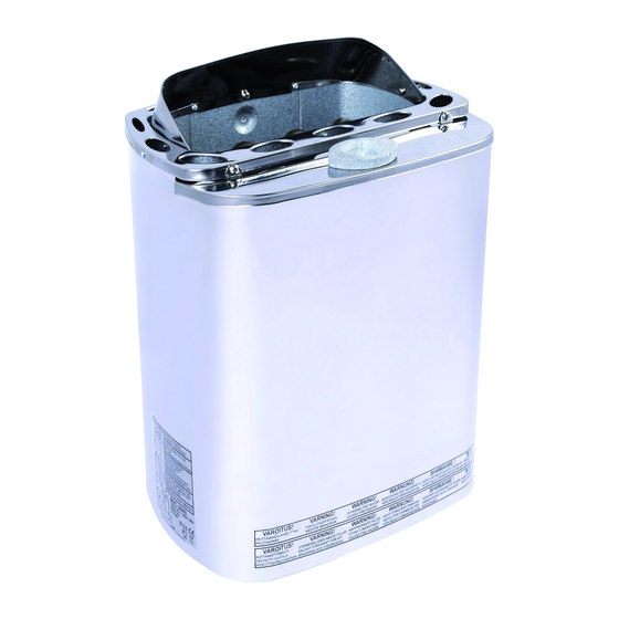
MNC-23NS
Complimenti per l'acquisto della stufa con evaporatore SAWOTEC.
Prima di utilizzarla, si prega di leggere attentamente questo manuale.
Il sensore della temperatura deve essere posizionato sopra la stufa.
Per ulteriori informazioni, consultare il manuale dell'unità di comando esterna.
Congratulations on your purchase of a SAWOTEC heater/steam generator.
Please read the manual carefully before using the product.
The Safety Temperature Sensor has to be mounted above the heater.
Check the manual of the external control unit for further instructions.
STUFA ELETTRICA
PER SAUNA CON
EVAPORATORE
INTEGRATO
ELECTRIC SAUNA
HEATER/STEAM
GENERATOR
MANUALE
MANUAL
MNC-30NS
MNC-36NS
Resistenze
Heating Elements
Vaschetta per gli aromi
Scent Basin
Contenitore dell'acqua
Water Tank
Indicazione del livello dell'acqua
Water Level Indicator
(MNC-30NS, MNC-30NSF
MNC-36NS, MNC-36NSF)
Numero seriale
Serial Number
Non utilizzabile in USA, Canada e Mexiko.
Not for use in the USA, Canada and Mexico.
ITALIANO / ENGLISH
MINI COMBI
DISPONIBILE NELLE
SEGUENTI VERSIONI:
AVAILABLE AS
• PREMIUM
• TRENDLINE
• FIBERCOATED
• AUTOREFILL
Advertisement
Table of Contents

Subscribe to Our Youtube Channel
Related Manuals for Sawotec MINI COMBI


Summary of Contents for Sawotec MINI COMBI
- Page 1 Il sensore della temperatura deve essere posizionato sopra la stufa. Per ulteriori informazioni, consultare il manuale dell’unità di comando esterna. Congratulations on your purchase of a SAWOTEC heater/steam generator. Please read the manual carefully before using the product. The Safety Temperature Sensor has to be mounted above the heater.
-
Page 2: Table Of Contents
Indice Indicazioni di sicurezza ......................4 1. Introduzione ........................8 1.1. Mini Combi (MNC) ....................8 2. Istruzioni per il montaggio e l’installazione ..............8 2.1. Assemblaggio/Montaggio ..................8 2.1.1. Rubinetto a sfera ....................8 2.1.2. Coperchio dell’evaporatore ................10 2.1.3. - Page 3 Contents Safety Instructions ........................ 5 1. Introduction of the Combi Heater ..................9 1.1. Mini Combi (MNC) ....................9 2. Assembly and Installation Instructions ................9 2.1. Assembly ........................ 9 2.1.1. Ball Valve ......................9 2.1.2. Steamer Cover ....................11 2.1.3.
-
Page 4: Indicazioni Di Sicurezza
Indicazioni di sicurezza Osservare le seguenti misure di sicurezza per l’installazione della stufa e per l’utilizzo della sauna. Per l’utente: • Questo dispositivo non può essere utilizzato da persone (bambini inclusi) con capacità fisiche, sensoriali o mentali limitate o prive della sufficiente esperienza e del know-how necessari, a meno che non siano in presenza di una persona responsabile per la loro sicurezza e abbiano ricevuto da questa persona istruzioni su come usare il... -
Page 5: Safety Instructions
Safety Instructions Please take note of these safety precautions before using the sauna or when installing the heater. For user: • This product is not designed to be used by persons (including children) with limited physical or mental abilities and limited experience and knowledge except under close supervision by a responsible person with knowledge and experience or having been advised by such person. - Page 6 Per l’installatore: • I lavori di cablaggio e di riparazione devono essere eseguiti da personale qualificato. • Durante l’installazione della stufa per sauna, osservare le distanze minime di sicurezza (vedi fig. 4). • Leggere le istruzioni per il posizionamento ottimale del sensore del termostato nel manuale dell’unità...
- Page 7 For Technicians: • Wiring and repairs must be done by a certified electrician. • Follow the Minimum Safety Distances when mounting the heater (see Fig. 4). • The electronic and electric system should be mounted in a way so that incoming air will not interfere with it. The control must be mounted outside the sauna cabin.
-
Page 8: Introduzione
1. Introduzione 1.1. Mini Combi (MNC) • Un dispositivo combinato composto da stufa ed evaporatore con vaschetta per gli aromi. • Offre la possibilità di scegliere tra la sauna tradizionale e il bagno turco • Le parti metalliche e il serbatoio dell’acqua sono costruiti in acciaio inox e, per via del design unico delle resistenze, il serbatoio deve essere tenuto pulito •... -
Page 9: Introduction Of The Combi Heater
1. Introduction of the Combi Heater 1.1. Mini Combi (MNC) • A combination of a heater and steamer with Scent Basin. Allows users to choose from normal sauna to steam bathing. • Its metal parts and Water Tank are made of stainless steel and the unique design of the heating elements makes the Water Tank easy to keep clean. -
Page 10: Coperchio Dell'evaporatore
2.1.2. Coperchio dell’evaporatore • Per riporre o estrarre il coperchio dell’evaporatore, seguire le istruzioni nella fig. 2. Fig. 2 Coperchio dell’evaporatore Fig. 2 Steam Cover Applicazione del coperchio dell’evaporatore Estrazione del coperchio dell’evaporatore Attach the steamer cover as shown Remove the steamer cover as shown Premere verso il basso Premere verso il basso Push down... -
Page 11: Steamer Cover
2.1.2. Steamer Cover • Follow the instructions in attaching or detaching the Steamer Cover given in figure 2. 2.1.3. Scent Basin • There is a designated hole for the Scent Basin on the Steamer Cover. The Scent Basin is to be fitted on the hole as per Figure 3. -
Page 12: Cablaggio E Installazione
2.2.2. Cablaggio e installazione AVVERTENZA: È vietato l’utilizzo di cavi con isolamento in PVC come cavi di collegamento per la stufa combi, perché questo materiale diventa friabile con l’esposizione al calore. • L’installazione della stufa combi può essere eseguita solo da un elettricista specializzato, per garantire la sicurezza della medesima ed evitare guasti ai collegamenti elettrici •... -
Page 13: Electrical Wiring And Installation
2.2.2. Electrical Wiring and Installation NOTE: Using a PVC-insulated wire as connection cable for the Combi Heater is not allowed because this material easily becomes brittle when subjected to heat. • A certified electrician must do the installation of the Combi Heater to ensure safety and reliability of the electrical connections. -
Page 14: Installazione Della Schermatura Della Stufa Combi
2.2.5. Installazione della schermatura della stufa combi • Durante il funzionamento la stufa si scalda molto. Per evitare che essa venga toccata involontariamente, deve essere applicata una schermatura protettiva. La fig. 7 mostra le distanze da rispettare per l’installazione della schermatura. 2.2.6. -
Page 15: Installation Of Combi Heater Safety Guard
2.2.5. Installation of Combi Heater Safety Guard • The Combi Heater naturally gets very hot during operation. To avoid the risk of accidental contact with it, it is necessary to affix a Safety Heater Guard. Refer to Figure 7 on the distance requirements to be observed in installing the Safety Heater Guard. -
Page 16: Utilizzo Della Stufa Combi
3.2. Utilizzo della stufa combi ATTENZIONE! Formazione di fumo e odori durante il primo riscaldamento Sulle nuove resistenze si trovano materiali di consumo derivanti dal processo di produzione. Questi si disgregano al momento del primo riscaldamento della stufa. Ciò produce fumo e un odore sgradevole. In caso di inalazione, questi fumi e vapori sono nocivi per la salute. -
Page 17: Using The Combi Heater
3.2. Using the Combi Heater CAUTION! Smoke and odor formation when heating up for the first time Work materials from the manufacturing process will be present on the new heating elements. These evaporate when the sauna heater is heated up for the first time. This produces smoke and an unpleasant odor. -
Page 18: Produzione Di Vapore
3.3. Produzione di vapore • Se si getta acqua sulle pietre, aumentano l’umidità dell’aria nella sauna e la temperatura della stufa. • Il contenuto di umidità dell’aria dipende dalla quantità di acqua versata. • È sufficiente versare ogni volta tre mestoli di acqua per creare un’atmosfera piacevole. Non versare troppa acqua sulle pietre, altrimenti potrebbe schizzare sugli altri occupanti della sauna perché... -
Page 19: Producing The Steam
3.4. Using the Steamer • The Mini Combi Heater has a 2.5-liter Water Tank. When filled with 2.5-liter water, steam can be produced for approximately 1 hour if set to max. • To ensure ideal humidity, the Sauna temperature should be between 40 and 50 degrees Celsius, and the Steamer should be left on for 20 minutes to pre-heat the Sauna and produce sufficient amount of steam before bathing. -
Page 20: Livello Dell'acqua Minimo
3.4.2. Livello dell’acqua minimo • La stufa combi è provvista di un sistema di notifica di mancanza di acqua, per ricaricare il serbatoio di acqua prima che si svuoti completamente. • Quando il livello dell’acqua raggiunge il segno REFILL, si attiva il sistema di notifica di mancanza di acqua. -
Page 21: Low Water Level
3.4.2. Low Water Level • The Combi Heater is equipped with a Low Water Level Detection System, which prompts the user to refill water before the Water Tank runs dry. • Once the water reaches the REFILL mark, the Low Water Level Detection System will be activated. •... -
Page 22: Utilizzo Degli Aromi
3.6. Utilizzo degli aromi • È possibile utilizzare gli aromi in combinazione con la stufa combi. Essi vengono versati nell’apposita vaschetta. • Non versare gli aromi nella vaschetta a evaporatore acceso, perché potrebbe causare gravi ustioni. • Dopo l’utilizzo degli aromi, pulire la vaschetta con una spazzola e risciacquarla con acqua. 4. -
Page 23: Using Scents
3.6. Using Scents • It is possible to use liquid scents with the Combi Heater. You can pour them on the Scent Basin. Avoid pouring scents while the Steamer is on as it can cause serious burns. • Brush the Scent Basin and rinse with water after using scents. 4. -
Page 24: Specifiche Tecniche
5. Specifiche tecniche La tabella nella fig. 10 contiene vari parametri tecnici in relazione all’installazione della stufa combi. Fig. 10 Specifiche tecniche Fig. 10 Technical Data RESISTENZA DIMENSIONE DELLA STUFA MODELLO CABINA DELLA TENSIONE DI DIMENSIONE PIETRE COMANDO DI STUFA SAUNA ALIMENTAZIONE DEL CAVO... -
Page 25: Technical Data
5. Technical Data The table in Figure 10 gives guidance on various technical matters 6. The Sauna Room 6.1. How to Use the Sauna Taking a sauna bath is a simple affair without many rules. It’s a matter of getting inside the Sauna and enjoying the sensation. -
Page 26: Asciugatura Della Cabina Della Sauna Dopo L'uso
6.3. Asciugatura della cabina della sauna dopo l’uso La sauna deve essere asciugata dopo ogni utilizzo. • Aprire la griglia di ventilazione sul soffitto e accendere la stufa per accelerare il processo di asciugatura. • Assicurarsi che la stufa sia disattivata dopo che la cabina della sauna è asciutta. 6.4. -
Page 27: Drying The Sauna Room After Use
6.3. Drying the Sauna Room After Use • Always dry the Sauna after every use. • Open the ventilation louver on the ceiling and turn on the heater for a quick drying of the Sauna. • Make sure to turn off the heater once the Sauna Room is dried. 6.4. -
Page 28: Potenza Della Stufa Combi
8. Piastra riflettente media 9. Indicazione del livello dell’acqua (non per MNC-30NSB, MNC-36NSB) 10. Set di cavi 11. Set evaporatore Mini Combi a) Serbatoio con lastra di riscaldamento (1 kW) b) Limitatore della temperatura c) Regolatore della temperatura d) Valvola di scarico e) Set di cavi 12. -
Page 29: Combi Heater Output
7. Wall Mounting Sheet 8. Middle Reflection Sheet 9. Level Indicator (not MNC-30NSB, MNC-36NSB) 10. Wiring Set 11. Steamer Set Mini Combi a) Tank with heating Plate (1kW) b) Temperature Limiter c) Temperature Regulator d) Drainage valve e) Wiring set 12. - Page 30 Fig. 12 Rappresentazione esplosa di tutti i pezzi di ricambio Fig. 12 Exploded view of all spare parts ITALIANO...
- Page 31 Con riserva di modifiche. Subject to change without notice.
Need help?
Do you have a question about the MINI COMBI and is the answer not in the manual?
Questions and answers