Table of Contents
Advertisement
Quick Links
Product May Vary Slightly From Pictured.
CAUTION:
Weight on this product should not exceed 250 lbs.
This Product is Distributed Exclusively by
2040 N Alliance Ave, Springfi eld, MO 65803
www.staminaproducts.com
Customer Care
1 (800) 375-7520
Owner's
Manual
WARNING
!
Exercise can present a
h e a l t h r i s k . C o n s u l t a
physician before beginning
any exercise program with
this equipment. If you feel
faint or dizzy, immediately
d i s c o n t i n u e u s e o f t h i s
equipment. Serious bodily
i n j u r y c a n o c c u r i f t h i s
equipment is not assembled
and used correctly. Serious
bodily injury can also occur
if all instructions are not
followed. Keep others and
pets away from equipment
when in use. Always make
sure all bolts and nuts are
securely tightened prior to
each use. Follow all safety
instructions in this manual.
When calling for parts or
service, please specify
the following numbers :
Model#: 15-4845
S/N: _____________
STAMINA PRODUCTS
MADE IN CHINA
© 2020 Stamina Products, Inc.
2020, 09
Advertisement
Table of Contents

Subscribe to Our Youtube Channel
Related Manuals for Stamina 15-4845


Summary of Contents for Stamina 15-4845
- Page 1 Weight on this product should not exceed 250 lbs. This Product is Distributed Exclusively by STAMINA PRODUCTS MADE IN CHINA 2040 N Alliance Ave, Springfi eld, MO 65803 Customer Care © 2020 Stamina Products, Inc. 1 (800) 375-7520 2020, 09 www.staminaproducts.com...
-
Page 3: Table Of Contents
20. The Stamina® Magnetic Recumbent Exercise Bike 845 should be used by only one person at a time. 21. The Stamina® Magnetic Recumbent Exercise Bike 845 is for consumer use only. It is not for use in public or semipublic facilities. - Page 4 1 (800) 375-7520 customer.care@staminaproducts.com Hi! From all of us here at Stamina Products, thank you for your purchase. We know that you have big fitness goals in mind and we are here to help you along. Call us, email us, or send us a message on Facebook. Be sure to contact us if you have any questions on your new product.
-
Page 5: Before You Begin
845. better, look better, and enjoy life to its fullest. Providing you with a quality product is Stamina's It's a proven fact that a regular exercise top priority. However, sometimes there could be a program can improve your physical and mental missing or incorrectly sized part. -
Page 6: Equipment Warning, Caution & Notice Labels
EQUIPMENT WARNING, CAUTION & NOTICE LABELS This chart is provided to help identify the warning, caution, and notice labels on the Stamina® Magnetic Recumbent Exercise Bike 845. Please take a moment to familiarize yourself with all of the warning, caution, and notice labels. -
Page 7: Hardware Identification Chart
HARDWARE IDENTIFICATION CHART This chart is provided to help identify the fasteners used in the assembly process. Place the washers or the ends of the bolts or screws on the circles to check for the correct diameter. Use the small scale to check the length of the bolts and screws. -
Page 8: Assembly Instructions
ASSEMBLY INSTRUCTIONS Place all parts from the box in a cleared area and position them on the fl oor in front of you. Remove all packing materials from your area and place them back into the box. Do not dispose of the packing materials until assembly is completed. - Page 9 ASSEMBLY INSTRUCTIONS STEP 3 Attach the SEAT FRAME(16) to the SEAT SLIDER(15) with CARRIAGE BOLTS(M8x1.25x66mm)(25) and NYLOCK NUTS(M8x1.25)(26), and bolt BUTTON HEAD BOLT(M6x1x13mm)(22) from the bottom of the SEAT SLIDER(15). STEP 4 Attach the SEAT(19) to the SEAT FRAME(16) with BUTTON HEAD BOLTS(M6x1x13mm)(22). Attach the SEAT BACK(20) to the SEAT FRAME(16) with BUTTON HEAD BOLTS(M6x1x45mm)(23).
- Page 10 ASSEMBLY INSTRUCTIONS STEP 5 Slide the LEVER(17) onto the LEVER CONNECTOR(30) located under the SEAT(19) and secure with BUTTON HEAD BOLTS(M6x1x13mm)(22). STEP 6 Attach the HANDRAIL(18) to the SEAT SLIDER(15) with BUTTON HEAD BOLTS(M8x1.25x36.5mm) (102). Plug the PULSE SENSOR WIRE(107) into the PULSE SENSOR EXTENSION WIRE(100).
- Page 11 ASSEMBLY INSTRUCTIONS STEP 7 NOTE: The RIGHT PEDAL(112) has an R stamped on the end of the pedal shaft. The RIGHT PEDAL (112) has right hand threads and is tightened by turning clockwise. The LEFT PEDAL(91) has an L stamped on the end of the pedal shaft. The LEFT PEDAL(91) has left hand threads and is tightened by turning counterclockwise.
- Page 12 ASSEMBLY INSTRUCTIONS STEP 9 Attach the HANDLEBAR(3) to the UPRIGHT(2) with SOCKET HEAD BOLTS(M8x1.25x25)(5). Clip the HANDLEBAR COVER(6) onto the HANDLEBAR(3) to cover the SOCKET HEAD BOLTS(M8x1.25x25)(5). STEP 10 Plug the EXTENSION CONTROL CABLE(75) and PULSE SENSOR CONNECTION WIRE(101) into the connecting wires of the COMPUTER(1), and push the excess wires back into the UPRIGHT(2).
-
Page 13: Set Up Instructions
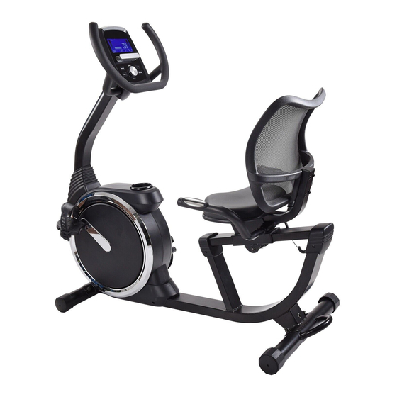
SET UP INSTRUCTIONS Place the Stamina® Magnetic Recumbent Exercise Bike 845 in the area where it will be used. It is recommended that the Stamina® Magnetic Recumbent Exercise Bike 845 be placed on an equipment mat. The Stamina® Magnetic Recumbent Exercise Bike 845 is approximately 51.1 inches long (max.) x 23.6 inches wide x 46.3 inches tall. -
Page 14: Operational Instructions
OPERATIONAL INSTRUCTIONS SEAT ADJUSTMENT Proper seat adjustment is important. There is a rail on the MAIN FRAME(10) for sliding the SEAT SLIDER(15) to allow users to adjust the position of the SEAT(19) for effi cient exercise. 1. Refer to the detail view below. Push down the LEVER(17) to unlock the SEAT SLIDER(15) until the SEAT(19) can be moved. -
Page 15: Computer Instructions
COMPUTER INSTRUCTIONS Your Stamina® Magnetic Recumbent Exercise Bike 845 utilizes a magnetic braking system to create resistance for your workout. You control the amount and pattern of this resistance by means of the advanced computer console mounted at the center of the Handlebar. We recommend that you use this computer console to vary your workout from session to session and note your progress toward your fi... - Page 16 COMPUTER INSTRUCTIONS Program Profi le Main Screen Programs Switch to display every 6 seconds Heart Symbol while exercising. LCD DISPLAY INSTRUCTIONS TIME: Displays fl ashing “0:00” for presetting the program time during setup, from 1:00 to 99:00 minutes, and counts down from the preset value. If no value is preset, displays the time during exercise, from 1 second up to 99:59 minutes.
- Page 17 COMPUTER INSTRUCTIONS The computer uses the ADAPTER(104) as a power source. Once power is on, the computer will then display all items on the screen and a “beep” will sound for two seconds, then skip to initial mode as shown in illustration 1.
- Page 18 COMPUTER INSTRUCTIONS PRESET PROGRAMS: These are 12 preset automatic programs. The profi les are shown on the LCD display of the computer. Use the UP/DOWN dial and MODE button to select the desired program. (P01) (P02) (P03) (P04) (P05) (P06) (P07) (P08) (P12)
- Page 19 COMPUTER INSTRUCTIONS ) HEART RATE CONTROL PROGRAMS: There are four preset automatic heart rate control programs, 55%, 75%, 90%, and TA (Target Heart Rate). You must always hold the Pulse Sensors on the Handrail with both hands when using the heart rate control programs. You must input your age for determining your Maximum Heart Rate.
- Page 20 COMPUTER INSTRUCTIONS HEART RATE CONTROL PROGRAM OPERATION 1. Start pedaling or press any button to wake up the computer. Press the RESET button to skip to program selecting mode to select the heart rate control program. Or, press the RESET button and hold it down for two seconds to skip to initial mode.
- Page 21 COMPUTER INSTRUCTIONS When running the target watt control program, the program will monitor your pedaling speed and adjust the workload The program will adjust the workload automatically to keep your workload as close as possible to automatically. the preset target WATT. For example, if the preset target WATT is 120 and you pedal with proper speed, the display will be as shown in the illustration.
- Page 22 COMPUTER INSTRUCTIONS OPERATION NOTES 1. When running a program, the main screen automatically scans TIME, SPEED, RPM, DISTANCE, CALORIES, WATT, and PULSE in sequence with a change every six seconds. You can press the MODE button to select each function for display on the Main Screen, but the SCAN function will stop. Quickly press the START/STOP button twice to activate the SCAN function again.
- Page 23 COMPUTER INSTRUCTIONS PULSE RECOVERY FUNCTION The PULSE RECOVERY function measures how quickly you return to a resting heart rate after exercising. You can use this function to measure improvement as you get into shape. The computer will monitor your heart rate for 60 seconds and calculate a pulse recovery value from F1 to F6. F1.0 = Excellent F2.0 = Good F3.0 = Fair...
- Page 24 Women (fat %) 10 - 19% 20 - 29% 30 - 34% 35% plus POWER SOURCE: The COMPUTER(1) uses the ADAPTER(104) as a power source. Use the Stamina® Magnetic Recumbent Exercise Bike 845 with the ADAPTER(104) plugged into an electrical outlet.
-
Page 25: Storage
3. Do not step on any portion of the plastic cover when getting on or off the Stamina® Magnetic Recumbent Exercise Bike 845. This can cause the plastic cover to crack. -
Page 26: Conditioning Guidelines
CONDITIONING GUIDELINES How you begin your exercise program depends on your physical condition. If you have been inactive for several years or are severely overweight, start slowly and increase your workout time gradually. Increase your workout intensity gradually by monitoring your heart rate while you exercise. Remember to follow these essentials: Have your doctor review your training and diet programs. -
Page 27: Warm-Up And Cool-Down
WARM-UP and COOL-DOWN Warm-Up The purpose of warming up is to prepare your body for exercise and to minimize injuries. Warm up for two to fi ve minutes before strength training or aerobic exercising. Perform activities that raise your heart rate and warm the working muscles. Activities may include brisk walking, jogging, jumping jacks, jump rope, and running in place. -
Page 28: Product Parts Drawing
PRODUCT PARTS DRAWING FRONT BACK... -
Page 29: Parts List
PARTS LIST PART# PART NAME Computer Upright Handlebar Screw, Round Head (M5 x 0.8 x 10mm) Bolt, Socket Head (M8 x 1.25 x 25mm) Handlebar Cover Bolt, Button Head w/ Washers (M8 x 1.25 x 16mm) Left Cover Decoration Ring Main Frame Front Stabilizer Screw, Round Head (M4 x 12mm) - Page 30 PARTS LIST PART# PART NAME Wavy Washer (S20) Plastic Spacer (ø20.1 x ø27 x 7mm) Screw, Round Head (M4 x 10mm) Mounting Bracket Sensor Wire Nylock Nut (M10 x 1.5) Idler Shaft Support Plate Idler Shaft Wavy Washer (S15) C Ring (ø10mm) V-Ribbed Belt (240-J5) Bearing (6202RS) Flange Nut (M10 x 1.0)
- Page 31 PARTS LIST PART# PART NAME Foam Tube (ø23 x ø600 x 3mm thick) Arc Washer (M4) Screw, Round Head Self-Drilling (M4 x 22mm) Pulse Sensor Extension Wire (1900mm long) Pulse Sensor Connection Wire (650mm long) Bolt, Button Head (M8 x 1.25 x 36.5mm) Bolt, Hex Head (M6 x 1 x 16mm, with threadlocker) Adapter, Output 9V, 500mA Control Cable (950mm long)
-
Page 32: Warranty
To implement this limited warranty, send a written notice stating your name, date, and place of purchase and a brief description of the defect along with your receipt to Stamina Products, Inc. 2040 N Alliance Ave, Springfi eld, Missouri, USA, MO 65803, or email us at customer.care@staminaproducts.com, or call us at 1-800-375-7520. -
Page 33: Notes
NOTES... -
Page 34: Fax/Mail Ordering Form
2040 N Alliance Ave, Springfi eld, MO 65803 Would you like to recieve email information or special off ers from Stamina Products? Register at contact.staminaproducts.com TO REGISTER YOUR PRODUCT To enact your warranty, please register your product by going to register.staminaproducts.com. Please have your product model number (printed on the cover of this owner’s manual) and the serial number (printed on the black and white sticker on your...
Need help?
Do you have a question about the 15-4845 and is the answer not in the manual?
Questions and answers