Table of Contents
Advertisement
Quick Links
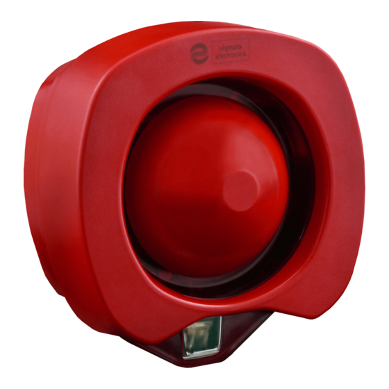
ΒSR-5132/WP
COMMUNICATION PROTOCOL
MAIN VOLTAGE
STANDBY CONSUMPTION
ALARM CONSUMPTION
MAXIMUM SOUND LEVEL IN 1 METER
BEACON
ENVIROMENTAL TYPE
MOUNTING
MAXIMUM LOOP CURRENT (Ic max, -L in/out)
MAXIMUM SWITCH CURRENT (Is max, -L in/out)
MAXIMUM SERIES RESISTANCE (Zc max, -L in-out)
MAXIMUM LEAKAGE CURRENT IN ISOLATION MODE (I max, -L in/out)
ISOLATION VOLTAGE (Vso min-max)
RECONNECT VOLTAGE (Vsc min-max)
COVER (y)
MOUNTING HEIGHT (x)
COVER AREA CODE
COVER AREA
FLASHING RATE
FLASHING COLOUR
DEGREES OF COVER PROTECTION
PRODUCED IN ACCORDANCE WITH
OPERATING TEMPERATURE RANGE
RELATIVE HUMIDITY
CONSTRUCTION MATERIALS
EXTERNAL DIMENSIONS
TYPICAL WEIGHT
GUARANTEE
GENERAL
This device is used as an indication of a fire panel
that sounds a warning signal from the siren and
provides visual indication using the beacon. The
sound level and the luminous signal it produces
covers an area of several square meters. It is
compatible with fire panels that support Olympia A
Protocol.
CONNECTION AND MOUNTING
1. Unscrew the screw and remove the plastic
cover using a flat screwdriver to the point under
the screw (Picture 1 page 2).
2. Unscrew the four screws and detach the plastic
from the base (Picture 2).
3. Drill the holes needed to pass the connection
cables. Place the cable glands and open a hole to
the center with a small screwdriver. Pass the
connection cables through the glands of the device
(Picture 3).
4. Use the supplied mounting materials to place the
Page 1 from 5
Waterproof addressable sounder with beacon
and integrated isolator
TECHNICAL CHARACTERISTICS
L
Thank you for your trust in our products
Olympia Electronics - European manufacturer
Olympia A Protocol
7.4 to 35.9mΑ
1 power LED
Wall mounted (W)
25mA pulses (6ms duration every 2sec)
6 meters in the peripheral of the beacon with 180° angle
2.4 meters max
86.4m³ maximun
Adjustable to 1 Hz or 0.5 Hz
EN 54-3, ΕΝ-54-17, EN 54-23
ABS/PC,PC
127x137x82 mm
base of the siren in height up to 2.4 meters from the
gound (Figure 1 page 2). Install the plastic plugs and
fasten the screws in the mounting holes. CAUTION!!
Make sure that the base of the siren is installed in the
correct orientation.
5. To adjust the type of the sound indication use
the DIP switches 1 to 5, according to Table 1 (page 4).
6. To adjust the sound level use the DIP switches 6
to 7, according to Table 2 (page 5).
7. To adjust the frequency of the flashing LED use
DIP switch 8 according to Table 3 (page 5).
8. Refit the plastic and fasten the 4 screws you
removed in step 2.
9. Refit the plastic cover and fasten the screw.
10. Test the operation of the device through the panel
after the installation.
The BSR-5132/WP integrates an isolator short circuit
which activates automatically by disconnecting the
defective node from the loop and allowing it's
detection though the panel.
11-30V DC
90μΑ
101dB
Type Β
1A
5A
50mΩ
9.3 - 10.6
10.7 - 12.7
W-2,4-6
Red
IP65
o
-25 to 70 C
Up to 95%
313 gr.
2 years
921513201_09_001
Advertisement
Table of Contents

Related Manuals for olympia electronics ΒSR-5132/WP


Summary of Contents for olympia electronics ΒSR-5132/WP
- Page 1 2 years GUARANTEE Thank you for your trust in our products Olympia Electronics - European manufacturer GENERAL base of the siren in height up to 2.4 meters from the This device is used as an indication of a fire panel gound (Figure 1 page 2).
- Page 2 Picture 2 Picture 1 +N1/+L -/-L +N2/+L NOTE!!! After finishing the installation place the sticker SEAL as shown in the picture Picture 3 above. W-x-y x=2,4m y=6m UID: In every device there is a double sticker with the UID (Unique Identifier) number.
- Page 3 DIP switches for siren and beacon settings. Terminal connection to the loop. Loop OUT Loop IN 1 2 3 4 5 6 7 8 Loop IN +N1/+L -/-L +N2/+L +N1/+L -/-L +N2/+L Loop OUT Indicating LED. Flashes periodically in quiescent state. Lit steady in case of alarm.
- Page 4 Table 1 Switch Frequency Main application setting Pattern Rate [1-2-3-4-5] Steady Continuous PFEER toxic gas 0-0-0-0-0 Intermitted 0.5Hz (1s On/1s Off) PFEER alert 1-0-0-0-0 Sweep 1s sweep German fire (DIN 33 404) 0-1-0-0-0 1200 - 500 Slow whoop 3s sweep, 0.5 sec silence Dutch fire (NEN 2575) 1-1-0-0-0 500 - 1200...
- Page 5 Sound level 1 Sound level 2 Sound level 3 Sound level 4 dB (A) (Flash (Flash dB (A) (Flash (Flash dB (A) (Flash (Flash dB (A) (Flash (Flash 1Hz) 0.5Hz) 1Hz) 0.5Hz) 1Hz) 0.5Hz) 1Hz) 0.5Hz) 18.7 16.6 26.5 24.5 18.7 16.6 26.5...
- Page 6 Olympia Electronics reserves the right to repair or to replace the returned goods and to or not charge the buyer depending on the reason of defection. Olympia Electronics reserves the right to charge or not the buyer the transportation cost.
Need help?
Do you have a question about the ΒSR-5132/WP and is the answer not in the manual?
Questions and answers