Advertisement
ΒS-531/1/MAR
OPERATION VOLTAGE
MAXIMUM CONSUMPTION
MAXIMUM SOUND OUTPUT in1m
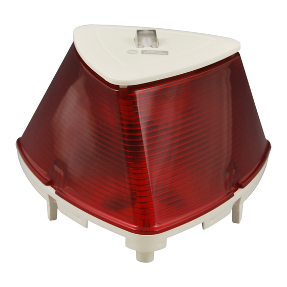
BEACON
ΤYPE OF APPLICATION ENVIRONMENT
MOUNTING
COVERAGE (y)
MOUNTING HEIGHT (x)
COVERAGE VOLUME CODE
COVERAGE VOLUME
FLASH RATE
FLASH COLOUR
DEGREES OF COVER PROTECTION
PRODUCED IN ACCORDANCE WITH
OPERATION TEMPERATURE RANGE
RELATIVE HUMIDITY
CONSTRUCTION MATERIAL
EXTERNAL DIMENSIONS
TYPICAL WEIGHT
GUARANTEE
GENERAL
This device is Visual Alarm Devices (VAD) for
fire detection panels that offer a strong sound
output and an optical warning with a beacon
and is used on ships. The strong sound and
the optical warning beacon cover many
square metres. It features two inputs (N1, N2)
for the production of two different sounds.
This device can co-operate with any fire
detection panel (BSR-2104/MAR, BSR-
2114/MAR, BS-1632, BS-1634, BS-1636, BS-
636).
Installation and Connection
1. First, remove the retaining screw, place a
flat blade screwdriver in the holes of the
plastic hooks and remove the plastic cover
(Image 1 on page 2).
2. Remove carefully the beacon connector
(Image 2 on page 2).
3. Use the supplied mounting parts to install the
siren's base at a height of 2.4 metres from
the floor (figure 1 on page 2). Place the
plastic plugs and fasten the screws to the
mounting holes. Attention!! Make sure that
the siren's base is installed upwards as
shown in figure on page 4.
4. Place the caps and make a hole in the center
Page 1 from 5
SOUNDER WITH BEACON FOR FIRE DETECTION PANEL
ΤΕCHNICAL CHARACTERISTICS
EN 54-3:2001+A1:2002+A2:2006, EN 54-23:2010, EN 50130-4:2011, IEC 60092-504 3 Ed.:2001+Cor1:2011, IEC 60533:1999 Edition 2.0
Thank you for your trust in our products
Olympia Electronics - European manufacturer
21-28V DC
1.2W
94dB (sound effect 1)
1 Power LED
Τype Α
Wall
6 m around the siren at an angle of 180°
2.4m max
W-2.4-6
86.4m³ (max)
1 Hz (Switchable to 0.5 Hz)
Red
IP 42C
o
0 to 60 C
Up to 95%
Bayblend FR3010, transparent polycarbonate
141 x 141 x 100 mm
230gr.
2 years
using a small screwdriver. Pass through the
caps the cables to connect the device.
5. The (+N1 or the +N2) terminal block is
connected to the (+) output of Alarm-1 or
Alarm-2 of the panel and the (-) of the
terminal block is connected to the (-) output
of Alarm-1 or Alarm-2 of the panel.
Accordingly connect in parallel all the sirens.
(The maximum number of sirens depends on
the type of the panel).
6. To select various sound effects use the
dipswitch 1, 2 and 3 and choose the
diserable sound effect, according to tables 2
and 3 on page 3.
7. For LED effect variation use the dipswitch 4
(Table 1) on page 2. On the last siren of the
line, we must connect in parallel with its
power cables, the terminal resistor that was
removed from the alarm contacts of the
panel.
8. Reinstall the beacon connector (step 2).
Refit the plastic cover until the plastic hooks
are securely attached (step 1) and fasten the
retaining screw (torque 0.6Nm). Attention!!
Make sure that the siren's cover is installed
in the correct orientation.
9. Test the device after installation.
rd
921531009_09_004
Advertisement
Table of Contents

Related Manuals for olympia electronics ΒS-531/1/MAR


Summary of Contents for olympia electronics ΒS-531/1/MAR
- Page 1 230gr. 2 years GUARANTEE Thank you for your trust in our products Olympia Electronics - European manufacturer GENERAL using a small screwdriver. Pass through the This device is Visual Alarm Devices (VAD) for caps the cables to connect the device.
- Page 2 Image 2 Image 1 2 3 4 D i p s w i t c h TO FIRE s i r e n a n d DETECTION b e a c o n Image 3 selections PANEL W-x-y x=2.4m y=6m Figure 1 W -Wall Mounted Device TABLE 1 LED effect...
- Page 3 Page 3 from 5 921531009_09_004...
- Page 4 Olympia Electronics reserves the right to repair or to replace the returned goods and to or not charge the buyer depending on the reason of defection. Olympia Electronics reserves the right to charge or not the buyer the transportation cost.
- Page 5 Figure which shows the correct positioning of the base Horizontal line parallel with the ceiling Wall hole diameter 6mm Page 5 from 5 921531009_09_004...
Need help?
Do you have a question about the ΒS-531/1/MAR and is the answer not in the manual?
Questions and answers