Table of Contents
Advertisement
Available languages
Available languages
Quick Links
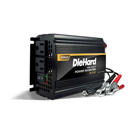
OPERATOR'S MANUAL / MANUAL DEL USUARIO
425W Power Inverter
Inversor de energía de 425 vatios
Model / Modelo:
28.71496
CAUTION:
Read and follow all safety
rules and operating instructions
before every use of this product.
SAVE THESE INSTRUCTIONS.
Lea y siga todas las reglas
de seguridad e instrucciones de uso
antes de cada uso de este producto.
GUARDE ESTAS INSTRUCCIONES.
ATENCIÓN:
0099001101-03
Advertisement
Table of Contents

Related Manuals for DieHard 28.71496


Summary of Contents for DieHard 28.71496
- Page 1 OPERATOR’S MANUAL / MANUAL DEL USUARIO 425W Power Inverter Inversor de energía de 425 vatios Model / Modelo: 28.71496 CAUTION: ATENCIÓN: Read and follow all safety Lea y siga todas las reglas rules and operating instructions de seguridad e instrucciones de uso before every use of this product.
- Page 2 Schumacher Electric Corporation, Mount Prospect, IL 60056 FOR CUSTOMER ASSISTANCE OR REPLACEMENT PARTS, CALL 1-800-621-5485 TOLL-FREE DieHard is a registered trademark of KCD IP, LLC, in the United States, and Sears Brands, LLC in other countries, used under license. GARANTÍA LIMITADA DIEHARD DURANTE UN AÑO desde la fecha de venta, este producto está...
-
Page 3: Table Of Contents
CONTENTS IMPORTANT SAFETY INSTRUCTIONS .............. 5 PERSONAL SAFETY PRECAUTIONS ..............6 FEATURES ......................6 BEFORE USING YOUR INVERTER ..............6 FASTENING THE INVERTER TO A FLAT SURFACE .......... 8 CONNECTING INVERTER CABLES ..............9 OPERATING INSTRUCTIONS ................9 POWER SOURCE ....................10 LED INDICATOR AND SHUTDOWN PROTECTION ......... - Page 4 CONTENIDOS INSTRUCCIONES IMPORTANTES DE SEGURIDAD ........14 PRECAUCIONES DE SEGURIDAD PERSONAL ..........15 CARACTERÍSTICAS ..................15 ANTES DE USAR SU INVERSOR ..............16 PARA SUJETAR EL CONVERTIDOR A UNA SUPERFICIE PLANA ....18 PARA CONECTAR LOS CABLES DEL INVERSOR ........... 18 INSTRUCCIONES DE OPERACIÓN ..............
-
Page 5: Important Safety Instructions
1. IMPORTANT SAFETY INSTRUCTIONS SAVE THESE INSTRUCTIONS – This manual will show you how to use your inverter safely and effectively. Please read, understand and follow these instructions and precautions carefully, as this manual contains important safety and operating instructions. WARNING: The inverter’s output is 110V AC and can shock or electrocute, the same as any ordinary household AC wall outlet. -
Page 6: Personal Safety Precautions
• Incorrect operation of your inverter may result in damage and personal injury. • This device does not include an internal Ground Fault Circuit Interrupter (GFCI). For GFCI protection, use a Coleman Cable 02822 GFCI outlet. • Use only 25 amp fuses. 2. - Page 7 When you turn on a device or a tool that runs on a motor, the device goes through two stages: 1. Start Up – Requiring an initial surge of power (commonly known as the “starting” or “peak” load). 2. Continuous Operation – Power consumption drops (commonly known as the “continuous”...
-
Page 8: Fastening The Inverter To A Flat Surface
4. Line filter capacitors 5. Shaded pole motors 6. Fan motors 7. Microwave ovens 8. Fluorescent and high intensity lamps (with a ballast) 9. Transformer less battery chargers Using the inverter with any of these devices may cause the device to run warmer or overheat. -
Page 9: Connecting Inverter Cables
6. CONNECTING INVERTER CABLES The inverter and power source must be in the OFF mode. IMPORTANT: Make sure you connect your inverter to a 12 volt power supply only. INVERTER CONNECTION: NOTE: Determine whether you will be using the battery clips (425 watt output maximum) or the 12V accessory plug (100 watts maximum). -
Page 10: Power Source
6. Plug the device into the inverter AC outlet. 7. Turn the inverter on. 8. Turn the device on. 9. To disconnect, reverse the above procedure. NOTE: If more than one device is to be powered, start one device at a time to avoid a power surge and overloading the inverter. -
Page 11: Led Indicator And Shutdown Protection
9. LED INDICATOR AND SHUTDOWN PROTECTION The LED glows GREEN automatically when plugged into a 12 volt DC source and will not glow under the following conditions: 1. When the power input from the vehicle’s battery drops to approximately 10±0.5 volts, low battery shutdown occurs and inverter shuts off. Solution: recharge or replace the battery. -
Page 12: If The Inverter's Fuse Blows
11. IF THE INVERTER’S FUSE BLOWS Your power inverter is fitted with a fuse, which should not have to be replaced under normal operating conditions. A blown fuse is usually caused by reverse polarity or a short circuit within the device or equipment being operated. If the fuse does blow: 1. -
Page 13: Specifications
13. SPECIFICATIONS Maximum continuous power ..............425 Watts Surge capability (0.1 second) ............... 850 Watts No load current draw ................0.6A DC Waveform ................Modified Sine Wave Input voltage ................10.0V-15.0V DC Output voltage ................110V-125V AC Low battery voltage alarm (buzzer) ..........10.5V±0.5V DC Low battery voltage shutdown .............10.0V±0.5V DC High battery voltage shutdown .............16V ±... -
Page 14: Instrucciones Importantes De Seguridad
1. INSTRUCCIONES IMPORTANTES DE SEGURIDAD GUARDE ESTAS INSTRUCCIONES – Este manual le mostrará cómo utilizar su inversor en forma segura y efectiva. Por favor, lea, comprenda y siga estas instrucciones y precauciones cuidadosamente, ya que este manual contiene instrucciones operativas y de seguridad de importancia. ADVERTENCIA: La salida del inversor es de 110V CA y puede dar una descarga o electrocutar igual que cualquier toma de corriente de pared doméstica de CA ordinaria. -
Page 15: Precauciones De Seguridad Personal
• No modifique las tomas de CA de ninguna manera. • No trate de extender o cambiar de forma alguna el cable de corriente de 12V sujeto a su inversor. • La operación incorrecta de su inversor puede resultar en daño y lesión personal. •... -
Page 16: Antes De Usar Su Inversor
4. ANTES DE USAR SU INVERSOR • Este inversor ha sido diseñado para ser usado con una sola batería hasta el grupo 31 (130 Ah o menos). La fuente de energía recomendada debe ser de una batería de ciclo profundo de 12 voltios, debido a sus altas reservas de energía. Las baterías regulares para automóviles son recomendadas sólo por un corto período de tiempo de una hora o menos. - Page 17 NOTA: El límite de 100 watts es para adaptar la proporción del fusible a todos los vehículos. Algunos vehículos pueden permitir la salida. Si el fusible del vehículo se funde cuando cambie al aparato que intenta usar, solo tiene dos opciones: Usar un aparato más pequeño o así...
-
Page 18: Para Sujetar El Convertidor A Una Superficie Plana
5. PARA SUJETAR EL CONVERTIDOR A UNA SUPERFICIE PLANA Por comodidad su convertidor puede ser sujetado a una superficie plana, horizontal o verticalmente. El área donde el convertidor será sujetado debe ser seca, bien ventilada y estar alejada de cualquier material o gases combustibles. 1. -
Page 19: Instrucciones De Operación
7. INSTRUCCIONES DE OPERACIÓN 1. Conecte el inversor (ver la sección Para Conectar los Cables del Inversor). 2. Cambie el interruptor del inversor a la posición de ENCENDIDO (ON) (I). 3. La luz del indicador LED debe brillar VERDE verificando que el inversor está recibiendo energía. -
Page 20: Fuente De Energía
8. FUENTE DE ENERGÍA Su batería de automóvil o marina promedio a toda carga proporcionará un abastecimiento de energía amplio para él inversor por aproximadamente dos a tres horas cuando el motor está apagado. El tiempo total que el inversor funcionará... -
Page 21: Cómo Funcionan Los Inversores De Corriente
10. CÓMO FUNCIONAN LOS INVERSORES DE CORRIENTE Hay dos etapas involucradas en la transformación de la energía de 12V de CD (batería) a 110V de CA (voltaje doméstico): ETAPA 1: El inversor de corriente usa un transformador de CD a CD para aumentar la aportación de voltaje de 12V de CD de la fuente de energía a 145V de CD. -
Page 22: Especificaciones
PROBLEMA CAUSA POSIBLE SOLUCIÓN La luz LED roja está La clavija accesoria Verifique la posible presencia encendida y la luz de 12V o los ganchos de una conexión defectuosa verde no. no se encuentran bien a la batería o al bastidor. conectados a la batería. -
Page 23: Piezas De Repuesto
14. PIEZAS DE REPUESTO Fusibles: Fusibles de repuesto se pueden comprar en la mayoría de las tiendas de componentes electrónicos. Clavija accesoria de 12V con cables..........3899003535Z Cable de batería con abrazaderas..........3899003533Z 15. ANTES DE DEVOLVER A REPARACIONES Cuando surja un PROBLEMA DE FUNCIONAMIENTO DESCONOCIDO, por favor lea todo el manual y comuníquese con el número de atención al cliente para más información que no haga falta la devolución.
Need help?
Do you have a question about the 28.71496 and is the answer not in the manual?
Questions and answers