
Related Manuals for AVANT Snow Plow 1800


Summary of Contents for AVANT Snow Plow 1800
- Page 1 English Snow plow 2016 1 Operator's Manual for Attachment Snow Plow 1800 Snow Plow 2400 Product number V1800 mm A36795 V2400 mm A36796 www.avanttecno.com...
- Page 2 Snow plow 2016 1...
-
Page 3: Table Of Contents
Snow plow 2016 1 CONTENTS 1. FOREWORD ............................4 Warning symbols used in this manual ........................... 5 2. DESIGNED PURPOSE OF USE......................6 3. SAFETY INSTRUCTIONS FOR USING THE ATTACHMENT ............7 4. TECHNICAL SPECIFICATIONS ....................... 10 Safety labels and main components of the attachment ..................10 5. -
Page 4: Foreword
If you sell or transfer the equipment, be sure to hand over this manual to the new owner. If the manual is lost or damaged, you can request a new one from your Avant dealer or from the manufacturer. -
Page 5: Warning Symbols Used In This Manual
5 (30) Warning symbols used in this manual The following warning symbols are used throughout this manual. They indicate factors that must be taken into account to reduce the risk of personal injury or damage to property: WARNING: SAFETY ALERT SYMBOL This symbol means: “Warning, be alert! Your safety is involved!”... -
Page 6: Designed Purpose Of Use
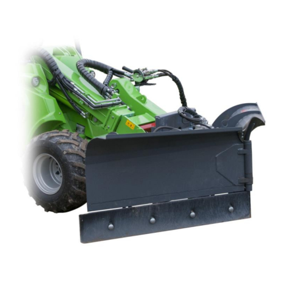
2. Designed purpose of use The AVANT Snow plow is an attachment suitable for use with AVANT multi purpose loaders shown in Table 1. The plow is a versatile articulated plow intended for clearing and pushing snow on street areas. It has two hydraulically movable blades. -
Page 7: Safety Instructions For Using The Attachment
7 (30) 3. Safety instructions for using the attachment Please bear in mind that safety is the result of several factors. The loader-attachment combination is highly powerful and improper or careless use or maintenance may cause serious personal injury or property damage. - Page 8 8 (30) Pay attention to the surroundings and any other persons and machines moving in the vicinity. Pay attention to the contours of the terrain and other hazards, such as branches and trees that can reach to the driver's area, loose rocks, and slippery surfaces.
- Page 9 Always lower the attachment to a safe position before leaving the driver's seat. Observe the local regulations concerning the use of the equipment on public roads. The loader may need to be registered for road use. Contact your local Avant dealer or local authorities for more information.
-
Page 10: Technical Specifications
Blade height: 770 mm Maximum input of hydraulic energy: max 22,5 MPa (225 bar) Compatible Avant loaders: See Table 1 The following equipment are recommended, but not mandatory equipment on the loader: Attachment control switch pack (optional equipment for some loader models) ... - Page 11 11 (30) Attachment identification plate A420622 / A420623 A46771 A46772 A46803 Table 3 - Decal locations and warning messages Decal Warning message A46771 Misuse hazard - Read instructions before use. A46772 Crushing hazard - Do not go under a raised attachment; stay away from raised equipment.
-
Page 12: Attaching The Attachment
12 (30) 5. Attaching the attachment Attaching the attachment to the loader is quick and easy, but it must be done carefully. The attachment is mounted to the loader boom by using the quick attach plate on the loader boom and the counterpart on the attachment. - Page 13 On Avant loaders the hydraulic hoses are connected using the multi connector system. If you have an Avant 300-700 series loader with the conventional quick couplers and wish to change to the multi connector system, contact your Avant dealer or service point for instructions or installation services.
- Page 14 14 (30) The lever should move easily all the way to its locking position. If the lever does not slide smoothly, check the alignment and position of the connector and clean the connectors. Also shut down the loader and release the residual hydraulic pressure.
-
Page 15: Electric Connection
15 (30) 5.1 Electric connection To operate the electric selection valve on the Snow plow, the electric harness must be connected to the loader. There are two options for the electric connection: The cable harness A34731, delivered with the attachment and equipped with a 2-position switch, is connected to the 12 V outlet near the driver's seat on the loader. -
Page 16: Instructions For Use
16 (30) 6. Instructions for use Check the attachment and the operating environment once more before starting to work, and that all obstacles have been removed from the operating area. Quick inspection of the equipment and the operating area before use are parts of ensuring safety and the best performance of the equipment. -
Page 17: Checks Before Use
17 (30) 6.1 Checks before use Check that all obstacles, including any possibly hidden ones, have been removed from the working area before operation. Make sure that the lower blade sections and their spring release system is in full working condition and unblocked before starting plowing work. -
Page 18: Operating The Snow Plow
18 (30) 6.2 Operating the snow plow The plow is equipped with a floating coupling bracket which can be set quickly and easily to correct operating position allows vertical movement of the attachment to keep the plowing edge and skids on the ground on uneven surfaces ... -
Page 19: Correct Operating Position
19 (30) 6.2.2 Correct operating position 1. Set the blade on the ground and tilt it into upright position by using the boom control lever of the loader: Lower the plow on the ground. Tilt of the quick coupling plate to vertical position. -
Page 20: Tips For Use
20 (30) 6.2.3 Tips for use If the snow plow is not adjusted into correct operating position, the following problems may arise: Possible case Solution Only the corners of the blade are in contact with Plow is tilted either towards front or back. Make sure that plow is in upright position. - Page 21 21 (30) When the electric switch is in 0-position, the auxiliary hydraulics control lever of the loader controls the right blade section of the plow independently: When the electric switch is in 1-position, the auxiliary hydraulics control lever of the loader controls the whole plow.
-
Page 22: Hinged Lower Blade Sections
22 (30) 6.4 Hinged lower blade sections To reduce the possibility of a sudden stop in case of hitting an obstacle, the plow is equipped with a spring release mechanism. The lower blade sections are held by compression springs which allows them to tilt backwards. -
Page 23: Cutting Edges Of The Plow
23 (30) 6.6 Cutting edges of the plow The edge plates of the plow sections can be replaced, as they wear during use. Depending on use, different blade types can be used. The plow has standard 305 mm hole spacing for fitting other blade edges. All edge options are symmetrical in a way that allows to rotate and install them upside down once the edge has worn. -
Page 24: Maintenance And Service
Repair all leaks immediately after detecting them; a small leak can quickly grow into a big one. Operate the attachment only with type of hydraulic oil that is accepted for use in Avant loaders. DANGER: Risk of high pressure fluid injection through skin - Release pressure before maintenance. -
Page 25: Inspection Of Metal Structures
Finding any fault means that the hydraulic hose or component must be replaced and the equipment must not be used until it is repaired. Spare parts are available from your nearest AVANT retailer or authorised service point. Leave the repair work to professional service technicians, if you don’t have adequate knowledge and experience about hydraulic assemblies and how to perform the repairing safely. -
Page 26: Blade Stoppers
26 (30) 7.5 Blade stoppers The blade stoppers on both sides of the plow frame reduce strain on hydraulic cylinders in case of collision. When the plow sections are set to fully rearward position the blade stoppers must be adjusted so that they are in contact with the plow sections. -
Page 27: Warranty Terms
27 (30) 8. Warranty terms Avant Tecno Oy grants a warranty of one year (12 months) from the date of purchase for the attachment it manufactures. The warranty covers repair costs as follows: Work costs are covered, if the repair is not performed at the factory. - Page 28 Hydraulisk snøskjær; redskap for Avant minilastere A36795 Hydraulisk sneblad; redskab til Avant Minilæssere A36796 Hydraulic snow blade; attachment for Avant loaders Hydraulische Schneepflug; Anbaugerät für Avant Radlader Lame de nivellement à commande hydraulique destinée à être utilisée avec les chargeuses Avant 21.11.2016 Ylöjärvi, Finland...
- Page 30 AVANT has a policy of continuous development, and retains the right to change specifications without notice. © 2016 Avant Tecno Oy. All rights reserved.
Need help?
Do you have a question about the Snow Plow 1800 and is the answer not in the manual?
Questions and answers