Table of Contents
Advertisement
Quick Links
Advertisement
Table of Contents

Related Manuals for BIXOLON SMP685


Summary of Contents for BIXOLON SMP685
- Page 1 User’s Manual SMP685 Thermal Printer Mechanism Rev. E http://www.bixolon.com...
- Page 2 SMP685 REVISION SHEET Revisions Design section Revision REV. Date Page Description 08.10.20 J.K.KIM J.S.LEE J.T.KIM 09.09.28 J.K.KIM J.S.LEE J.T.KIM Spec revision 12.09.19 J.K.KIM J.K.KIM J.G.KIM Spec revision 13.05.15 M.W.LEE J.S.LEE J.T.KIM Spec revision(685CB) Modified Contents & 20.06.24 M.H.YU J.S.LEE J.S.LEE...
-
Page 3: Table Of Contents
SMP685 ■ Table of Contents 1. Specifications ......................12 2. Exploded View ......................14 3. Component Names ...................... 15 4. Connector Pin Arrangement ..................17 4-1 Main FPC Cable (1mm 30Pin) .................. 17 5. Thermal Printer Head ....................18 5-1 Specifications......................18 5-2 Head Block Diagram .................... - Page 4 SMP685 8-5 Cleaning thermal head ....................38 9. Precautions in Designing External Case ..............39 10. Frame Ground ......................39 10-1 How to connect to the frame ground ............... 39 11. Precautions when fixing the platen roller block ............. 40 12.
- Page 5 (SMP685). BIXOLON is not responsible for any damage or loss occurring through improper handling of printer mechanism, or use of the product in a way that is not described in this manual, or other components of your company configuring the system.
- Page 6 SMP685 ※ Safety Precautions Take precautions with the following items when you design terminals or other products using the printer mechanism. Include the required precautions in the user’s manual so that users can use the products such as terminals safely.
- Page 7 SMP685 ※ Design Precautions Take precautions on following items when designing products such as terminals using the printer mechanism. a) Power on sequence should be as follows. - Startup: Apply Vdd and then Vp - Shutdown: Shutdown Vp and then Vdd b) The surge voltage between Vp and GND should be less than 10V.
- Page 8 SMP685 m) The door rotation system of the external case that holds the platen block should be installed while pressing down the center of the platen roller block. If it is installed by pressing down one side of the platen roller block, it may cause a printing problem or paper jamming.
- Page 9 SMP685 ※ Precautions in Handling Incorrect handling may damage or reduce the efficiency of the printer mechanism. Take precautions with the following. * If papers that are not recommended are used - Printing quality drops due to low thermal sensitivity.
- Page 10 SMP685 j) Do not apply force to FPC while connecting and disconnecting the connection terminal (printer connection terminal). It may damage FPC. k) Provide a warning to users so that they do not change the thermal paper discharge angle and do not pull the paper during printing. It may case printing defect or paper jamming.
- Page 11 SMP685 ■ Features of SMP685 printer mechanism This printer mechanism has the following features. * High Speed Printer - Support up to 90mm per second of printing speed. * High Resolution Printing - Smooth and accurate printing is supported using high-density printer head with a density of 8 dots/mm.
-
Page 12: Specifications
Product life Activation pulse resistance : 100million C, normal energy) Abrasion resistance : 50km Package : Bixolon standard package Impact resistance Height : 75 cm Directions : 1 corner, 3edges and 6 surfaces A. TF50KS-E2D(Paper thickness : 65 µm) of Nippon paper Industries Co., Ltd B. - Page 13 SMP685 Operation conditions by temperature / humidity Printing quality guarantee zone Operable zone *Note. 1) Printing speed depends on the controller processing speed and strobe pulse width. *Note. 2) In case of motor driving 1-2 phase, paper supply interval : 0.03125mm *Note.
-
Page 14: Exploded View
SMP685 2. Exploded View - 14 - Rev. E... -
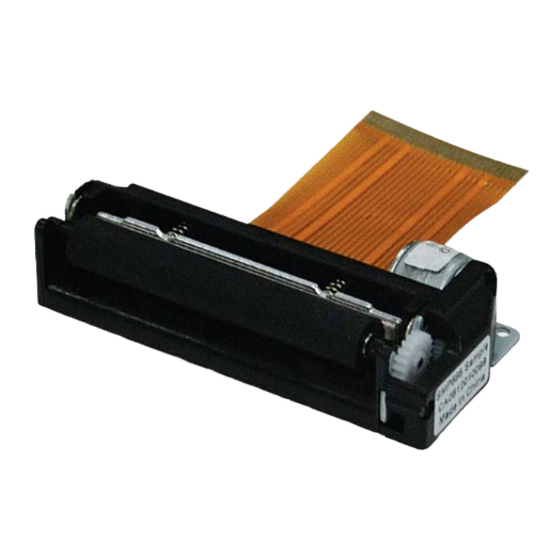
Page 15: Component Names
SMP685 3. Component Names Parts No Name Specifications Q’ty A/S KP05-00023A SECC T1.0(685CB/CJS) Frame lower KP05-00023B SECC T1.0(685CK) KM05-00019A PC-GF10(685CB/CJS) Frame upper KM05-00019B PC-GF10(685CK) Ass’y TPH TPH(AOI)+FPC(S)+Bracket AE05-00033B (AOI) +Sensor+Motor(685CK) Ass’y TPH TPH(AOI)+FPC(L)+Bracket AE05-00034B (AOI, FPC L) +Sensor+Motor(685CJS) Ass’y TPH... - Page 16 SMP685 13 KC05-00007A Screw-Tapping M1.7*7 6002-001052 Screw-Tapping M1.7*3 - 16 - Rev. E...
-
Page 17: Connector Pin Arrangement
SMP685 4. Connector Pin Arrangement 4-1 Main FPC Cable (1mm 30Pin) Pin No. Signal Function PS_IN Cathode for photo interrupter VSEN Photo interrupter power PS_OUT Emitter for photo interrupter Non connector Non connector Print Supply Voltage Print Supply Voltage Data IN... -
Page 18: Thermal Printer Head
SMP685 5. Thermal Printer Head Thermal head comprises a thermal device and thermal head driver that drives and controls the thermal device. Data input coming from SI terminal is “High” for printing and “Low” for not printing. The data coming from SI terminal are transmitted to the shift registers at the rising edge of the CLK signal. -
Page 19: Head Block Diagram
SMP685 5-2 Head Block Diagram COM: TPH Supply voltage (Vset) STB: STROBE (High active) nLAT: /LATCH (Low active) CLK: CLOCK SI: Data input SO: Data output TM: Thermistor VDD: TPH Logic voltage GND: Ground - 19 - Rev. E... -
Page 20: Printing Position Of Transmitted Data
SMP685 ※ Relationship between STB terminal and activated thermal device Block No. STB number Heating element number Dots / STB STB1 1 ~ 64 STB2 65 ~ 128 STB3 129 ~ 192 STB4 193 ~ 256 STB5 257 ~ 320... -
Page 21: Dimension Of Thermal Device
SMP685 5-4 Dimension of Thermal Device 5-4-1 Heat Element Dimensions 5-4-2 Print Area - 21 - Rev. E... -
Page 22: Electric Characteristics Of Thermal Head
SMP685 5-5 Electric Characteristics of Thermal Head Ta = 25℃±10°C 항목 비고 Symbol MIN. TYP. MAX. Umix 공급 전압 로직 전압 논리 전류 ALL-High High Level 입력전압 0.8xV Low Level 입력전압 0.2 xV SI,CLK,nLAT High Level 입력전류 STB at 5V STB at 3.3V... -
Page 23: Thermal Head Drive Timing Diagram
SMP685 5-6 Thermal Head Drive Timing Diagram ※ Caution When sufficient driver output delay time cannot be guaranteed, V can be changed significantly. Design the circuit so that V does not exceed the peak voltage. - 23 - Rev. E... -
Page 24: Maximum Ratings (Printer Head Ambient Temperature: 25℃)
SMP685 5-7 Maximum Ratings (Printer head ambient temperature: 25℃) Items Maximum rating Condition Voltage among the connector terminals Never exceed Supply Voltage (V 8.5V Driver IC’s high voltage limit, 10V. 0.16 mJ/dot * Note. Supply Energy (E S.L.T. = 0.63ms/line 0.11 mJ/dot... -
Page 25: Peak Current
SMP685 5-9 Peak Current Most cases in the following equation can be used to calculate the peak current of the printer head operation. Pay special attention to voltage drop of the circuit. х V = ------------------ Rave Rave : Average resistance (176 Ω) -
Page 26: Head Operation Pulse Width (Actual Measurement)
SMP685 ※ Operating temperature and head pulse width (calculation example) 사용 온도 및 구동 전압에 대한 Head Pulse Width Head Pulse Width vs Operating Temperature 온도 perature 9.5V Temperature (℃) 5-10-3 Head operation pulse width (actual measurement) Thermister temperature (℃) Head pulse width (usec) Vset=9.5V, 100mm/s... - Page 27 SMP685 TEMPERATURE ℃ Temperature(℃) (㏀) Temperature(℃) (㏀) 316.154 24.111 233.694 19.517 174.734 15.904 132.078 13.044 100.862 10.765 77.774 8.935 60.524 7.458 47.511 6.259 37.606 5.280 30.000 2.801 - 27 - Rev. E...
-
Page 28: Detection Of Abnormal Temperature Of The Thermal Head
SMP685 ※ Recommended thermister circuit 10㏀/F 10㏀ 10㏀/F TM_out H_TMP TPH Thermistor LM393 3㏀/F 100㎋ 100㎋ Ground User side Printer side 5-10-5 Detection of abnormal temperature of the thermal head In order to protect the thermal head and to guarantee people’s safety, the abnormal temperature of the thermal head should be detected by both hardware and software. -
Page 29: Head History Control
SMP685 5-10-6 Head History Control One dot will be printed by THP per two motor steps. The minimum off-time should be guaranteed since the heating element of TPH should be cooled down sufficiently in order to achieve good printing quality. -
Page 30: Stepping Motor (Paper Feeding)
SMP685 6. Stepping Motor (Paper Feeding) 6-1 Specifications Items Specifications Type PM type stepping motor Drive Method Bi-polar chopper Excitation Method 2-2 Phase Terminal Voltage Vp : DC 4.75V ~ DC 8.5V Ω/Phase ±5% Wire Resistance Motor Control Current 0.33A/Phase Motor Drive Pulse 1440 pps Max. - Page 31 SMP685 - Constant voltage drive circuit (Vp=7.2V or 8.5V) BA6845FS 100㎋ 100㎌/16V IN11 IN11 VCC1 VCC2 IN21 IN21 FEED_A OUT11 IN12 IN12 OUT12 FEED_nA IN22 IN22 OUT21 FEED_B OUT22 FEED_nB GROUND GROUND GROUND GROUND Maximum drive time should be limited in order to prevent overheating of the motor.
-
Page 32: Drive Sequence (Motor Runs In A Counterclockwise Direction)
SMP685 6-3 Drive Sequence (Motor runs in a counterclockwise direction) ※ H: High / L: Low ※ Precautions when designing motor control circuit and software In order to stop the motor, excite the motor for one step period using the same phase as the final phase of the printing step. -
Page 33: Motor Timing Diagram
SMP685 6-4 Motor timing diagram 6-5 Drive frequency acceleration (acceleration control) Acceleration control is required in order to maintain power when driving the motor. Drive the motor in accordance with the acceleration step in the Table. The method of accelerating the motor is as follows... - Page 34 SMP685 ※ Acceleration Step(at 2-2Phase) Number of Speed Step Time Steps (pps) (㎲) Start 5000 4728 2922 2234 1894 1660 1494 1369 1270 1190 1123 1066 1016 1027 1069 1110 1148 1187 1224 1259 1290 1328 1360 1392 1422 1432...
-
Page 35: Sensor
SMP685 7. Sensor 7-1 Paper detection sensor and black mark detection sensor 7-1-1 Absolute Maximum Ratings (Ta = 25℃) Parameter Symbol Rating Unit ㎃ Forward current Input Reverse current ㎽ Power consumption Collector-Emitter voltage VCEO Emitter-Collector voltage VECO Output ㎃... -
Page 36: External Circuit For Paper Detection Sensor Sampling
SMP685 7-1-3 External circuit for paper detection sensor sampling Paper detection Paper detection sensor (PS OUT) signal level When there is paper When there is no paper High ※ Caution Check the actual performance of paper detection when you use the device as there will be a difference in detected voltage depending on the Vdd input voltage or sensor input/out resistance. -
Page 37: How To Handle The Printer Mechanism
SMP685 8. How to handle the Printer Mechanism 8-1 Installation of the thermal paper - Place the thermal paper correctly between the paper guide device of the printer mechanism and extend the tip of the thermal paper to the upper side by 2 inches (around 5cm) or more. -
Page 38: Cleaning Thermal Head
SMP685 8-5 Cleaning thermal head Thermal head should be cleaned as foreign substances on the thermal head surface may cause problems in printing after long hours of use. As the temperature of thermal head and peripheral devices may be very high right after printing, wait until the temperature goes down sufficiently before cleaning. -
Page 39: Precautions In Designing External Case
SMP685 9. Precautions in Designing External Case - As the amount of thermal paper installed in a roll becomes smaller, it is more likely to cause curling, causing printing failure or paper jamming. Check the performance by using thermal papers with high curling effects. -
Page 40: Precautions When Fixing The Platen Roller Block
SMP685 11. Precautions when fixing the platen roller block - The external case that fixes the platen roller block should have sufficient strength in design to prevent deformation or wobbling by impact, twist or external force, and the rotation axis that fixes the external case should be designed to prevent fluctuation in a left and right direction. -
Page 41: Exterior And Dimension
SMP685 12. Exterior and Dimension (SMP685) - 41 - Rev. E... - Page 42 SMP685 (SMP685CJS) - 42 - Rev. E...
- Page 43 SMP685 Product Approval Product Name SMP685 Manufacturer BIXOLON Product SMP685 User’s Manual Specifications Rev. E Company Name Approval Date Approved By Signature - 43 - Rev. E...
Need help?
Do you have a question about the SMP685 and is the answer not in the manual?
Questions and answers