Table of Contents
Advertisement
Quick Links
Advertisement
Table of Contents

Related Manuals for BIXOLON SMP6210


Summary of Contents for BIXOLON SMP6210
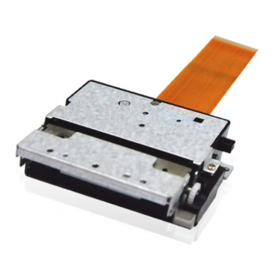
- Page 1 User’s Manual SMP6210 Thermal Printer Mechanism Rev. 1.01 http://www.bixolon.com...
- Page 2 SMP6210 REVISION SHEET Revisions Design section Revision REV. Date Page Description 1.00 10.01.08 J.K.KIM J.S.LEE J.T.KIM Modification on auto cutter 1.01 12.08.20 I.Y.PARK J.S.LEE J.T.KIM flow chart regarding chattering - 2 - Rev. 1.01...
-
Page 3: Table Of Contents
SMP6210 ■ Table of Contents 1. Specifications ......................14 2. Disassembly diagram ....................16 3. Part names ......................... 17 4. Connector pin arrangement ..................18 4-1 Main FPC cable (30Pin) ..................18 4-2 Connector Cable (Auto-cut) ..................18 4-3 FPC aux cable (BMS option) .................. 19 5. - Page 4 SMP6210 7. Sensor ......................... 35 7-1 Paper Detection Sensor and Black Mark Detection Sensor ........35 7-1-1 Absolute maximum rating ................35 7-1-2 Electrical Characteristics ................35 7-1-3 Paper Detection Sensor Sample External Circuits ........36 7-1-4 Black Mark Detection Sensor Sample External Circuits ......36 7-2 Platen Roller Block Detection Switch ..............
- Page 5 SMP6210 12. Designing the device to release the jamming of moving blade ......53 12-1 Designing the structure to clear the condition using tools ........53 12-1-1 Designing the structure to clear the condition using tools ......53 12-1-2 Designing the structure to clear the condition by pressing the button with finger 12-1-3 Designing the structure to use knob wheel (optional specifications) ..
- Page 6 Please read carefully and fully understand this user’s manual when you design printers or terminals using the printer mechanism (SMP 6210). BIXOLON is not responsible for any damage or loss occurred due to your company’s configuration parts or usage not included in this user’s manual or improper handling of the printer mechanism.
- Page 7 SMP6210 ※ Safety Precautions Take care with the following items when designing products such as terminals using the printer mechanism, and include precautions required for user’s manual so that users of the products such as terminals can use the products safely.
- Page 8 SMP6210 f) Precaution about temperature rise of the motor The temperature of step motor and the peripheral device is very high during or right after printing. Design the outer case so that users do not get a burn injury by touching the motor.
- Page 9 SMP6210 ※ Design Precautions Take precautions with the following items when designing products such as terminals using the printer mechanism. a) The sequence of applying power is as follows. - Startup: Apply Vdd and then apply Vp - Shutdown: Cut off Vp and cut off Vdd b) Surge voltage between Vp and GND must be lower than 10 V.
- Page 10 SMP6210 n) In order to prevent degradation of printing quality due to reverse rotation of the paper drive system, install/remove the platen roller block or feed the thermal paper by more than 20 steps during initialization after cutting using the cutter.
- Page 11 SMP6210 ※ Handling Precautions Incorrect handling of the printer mechanism will reduce the efficiency and damage the system. Precaution must be taken with the following. * When paper other than specified thermal paper is used. - Printing quality may drop due to low thermal sensitivity.
- Page 12 SMP6210 h) When printing at high speed in an environment of low temperature or high humidity, water drops might form on the printer mechanism due to steam generated by the thermal paper and the thermal paper might be damaged. Do not apply power until the water drops are completely dried out.
- Page 13 SMP6210 ■ Characteristics of SMP6210 Printer Mechanism This printer mechanism has the following characteristics. * Integrated cutter - Guillotine-type cutter is included. * High speed printing - Printing speed can be up to 70mm/s printing. * High resolution printing - Smooth and accurate printing using the high-density printing head of 8 dots/mm.
-
Page 14: Specifications
Abrasion resistance : 50km energy) Auto cutter : 1,000,000 cuts Package: Bixolon standard package Impact resistance Height: 75 cm Directions: 1 corner, 3 edges and 6 surfaces A. TF50KS-E (Paper thickness: 65 µm) of Nippon paper Industries Co., Ltd B. PD 160R (75 µm) of New Oji Paper Mfg, Co., Ltd. - Page 15 SMP6210 Operating conditions For temperature / humidity Printing quality is guaranteed Printer can be operated - 15 - Rev. 1.01...
-
Page 16: Disassembly Diagram
SMP6210 2. Disassembly diagram - 16 - Rev. 1.01... -
Page 17: Part Names
SMP6210 3. Part names Q’ty A/S Part No. Part name Descriptions Frame main + Shaft lever lock, Ass’y Frame main AF05-00009A Lever lock L, Lever lock R Ass’y TPH AE05-00030A TPH, Bracket tph, FPC, Sensor KM05-00025A Frame upper PC (Lupoy GP-2100) -
Page 18: Connector Pin Arrangement
SMP6210 4. Connector pin arrangement 4-1 Main FPC cable (30Pin) PIN NO SIGNAL Description CUT_SW Auto cutter switch EARTH Mechanism Earth FEED_2B Feeding motor FEED_2A Feeding motor FEED_1B Feeding motor FEED_1A Feeding motor COVER_SW2 Platen roller detector switch COVER_SW1 Platen roller detector switch... -
Page 19: Fpc Aux Cable (Bms Option)
SMP6210 4-3 FPC aux cable (BMS option) PIN NO SIGNAL Description BMS_IN Black Mark sensor Input Black Mark sensor Ground Black Mark sensor Ground BMS_OUT Black Mark sensor Output ※ User recommended connector - Number of terminals: 4 pins with 1.0 ㎜ pitch... -
Page 20: Thermal Printer Head
SMP6210 5. Thermal Printer Head Thermal head is configured with a thermal device and thermal head drive that drives and controls the thermal device. Data input from the SI terminal is “High” for printing and “Low” for not printing. Data from SI terminals are transferred to the shift registers at the rising edge of the CLK. -
Page 21: Head Block Diagram
SMP6210 5-2 Head Block Diagram STB: Strobe(High active) /LAT: Latch (Low active) CLK: Clock Data in TM: Thermistor - 21 - Rev. 1.01... -
Page 22: Printing Position Of Transferred Data
SMP6210 ※ Relationship between STB terminal and thermal device activation Strobe No. Dot No. Number of dots 1 ~ 64 65 ~ 128 129 ~ 192 193 ~ 256 257 ~ 320 321 ~ 384 5-3 Printing position of transferred data - 22 - Rev. -
Page 23: Dimensions Of Thermal Device
SMP6210 5-4 Dimensions of thermal device - 23 - Rev. 1.01... -
Page 24: Electrical Characteristics Of The Thermal Head
SMP6210 5-5 Electrical Characteristics of the Thermal Head Ta = 25℃±10°C Item Symbol MIN. TYP. MAX. Umix Remarks Supply Voltage at 5V Logic Voltage at 3.3V at 5V, ㎃ ALL-High Logic Current at 3.3V, ㎃ ALL-High 0.8 V Input Voltage 0.2 V... -
Page 25: Thermal Head Drive Timing Diagram
SMP6210 5-6 Thermal Head Drive Timing Diagram ※ V can fluctuate in big amplitude if the sufficient driver output delay time cannot be guaranteed. Design the circuit so that V does not exceed the peak voltage (Vp). - 25 -... -
Page 26: Maximum Condition (Ambient Temperature Of The Printer Head: 25℃)
SMP6210 5-7 Maximum Condition (Ambient temperature of the printer head: 25℃) Items Maximum condition Condition Voltage among the connector Supply Voltage(V 8.5V terminals Never exceed Driver IC’s high voltage limit, 10V 0.16mj/dot S.L.T. = 0.63ms Supply Energy (E Omax 0.23 mj/dot S.L.T. -
Page 27: Pulse Width Control Of The Head
SMP6210 5-10 Pulse Width Control of the Head 5-10-1 Voltage pulse width Control the width of the pulse depending on the operating voltage to maintain stable printing quality. The head pulse width can be obtained using the following equation. х N + Rave + R х... -
Page 28: Example Calculation Of Head Operating Pulse Width
SMP6210 5-10-3 Example calculation of head operating pulse width Thermistor temperature (℃) Head pulse width (usec) 5-10-4 Thermistor specifications - Electrical Specifications of Thermistor ▷ Rating 1) Operating temperature : -40 ~ +125 ℃ 2) Time constant : 5 sec (in the air) ▷... - Page 29 SMP6210 R std (kΩ) R std (kΩ) Temperature (℃) Temperature (℃) 1205.58 19.51 316.97 15.89 234.22 13.03 175.07 10.75 132.29 8.92 100.99 7.45 77.85 6.25 60.57 5.27 47.53 4.47 37.61 3.26 30.00 2.42 24.11 1.08 ※ Recommended Thermistor circuit +3.3V TPH Thermistor 10㏀...
-
Page 30: Detection Of Abnormal Temperature Of Thermal Head
SMP6210 5-10-5 Detection of abnormal temperature of thermal head In order to protect the thermal head and to guarantee the safety of the user, abnormal temperature of the thermal head must be detected from both hardware and software sides. ▷ Detection of abnormal temperature with software When the software detects a temperature higher than 60C from the thermistor of... -
Page 31: Step Motor (Paper Feed)
SMP6210 6. Step Motor (Paper Feed) 6-1 Specifications Item Specifications Type PM type Step Motor Drive method Bi-polar chopper Excitation type 1-2 Phase Terminal voltage Vp : Max DC 8.5V 10 Ω/Phase ±10% Wiring resistance Motor control current 0.85A/Phase Motor drive pulse 2240 pps Max. -
Page 32: Drive Sequence
SMP6210 6-3 Drive sequence Motor drive input pulse IN11 IN12 IN21 IN22 Step 1 Step 2 Step 3 Step 4 Step 5 Step 6 Step 7 Step 8 Motor Stop ※ H: High / L: Low ※ Precaution in designing motor control circuit and software In order to stop the motor, apply excitation for one step period using the same phase as the last phase of the printing step. -
Page 33: Drive Frequency Acceleration (Acceleration Control)
SMP6210 6-5 Drive Frequency Acceleration (Acceleration Control) Acceleration control is required to maintain driving power when driving the motor. Drive the motor according to the acceleration step in the table shown below. The procedure for accelerating the motor is as follows. - Page 34 SMP6210 ※ Acceleration step Step Speed (pps) Step time (usec) Step Speed(pps) Step time (usec) 3486 1541 3326 1561 3168 1580 3010 1601 2854 1621 2698 1643 2542 1664 2388 1687 2234 1708 2080 1753 1927 1799 1775 1844 1623...
-
Page 35: Sensor
SMP6210 7. Sensor 7-1 Paper Detection Sensor and Black Mark Detection Sensor 7-1-1 Absolute maximum rating (Ta = 25℃) Parameter Symbol Rating Unit ㎃ Forward current Input Reverse current ㎽ Power consumption Collector-Emitter voltage VCEO Emitter-Collector Voltage VECO Output ㎃... -
Page 36: Paper Detection Sensor Sample External Circuits
SMP6210 7-1-3 Paper Detection Sensor Sample External Circuits 180Ω/F 68㏀/F PS_IN 33Ω SG-105F PS_OUT PE_SENSOR 10㎋ Ground User side Printer side Paper detection Paper detection sensor signal level Paper is detected Paper is not detected High 7-1-4 Black Mark Detection Sensor Sample External Circuits (Optional specifications) 180Ω/F... -
Page 37: Platen Roller Block Detection Switch
SMP6210 performance by actually using the device. If there is anything wrong in performance, adjust the density of black mark or resistance value of *1) to set the product to optimum state. 7-2 Platen Roller Block Detection Switch 7-2-1 Sample external circuits 30㏀... -
Page 38: Auto Cutter
SMP6210 7-3 Auto Cutter To cut the paper automatically after printing - Cutting paper: Single layer thermal paper of general paper (Thickness: 50~100㎛) - Rated voltage Motor: DC 8.5V Current consumption: Max. 1.7A Switch: DC 5V±5% (Current consumption: MAX 5㎃) - Paper cutting guaranteed life Paper thickness of 65㎛: Cut 1,000,000 times... - Page 39 SMP6210 - Full cut: Forward full cut: 121 steps after switch OFF Backward full cut: 25 steps after switch ON - Partial cut: Forward partial cut: 85 steps after switch OFF Backward partial cut: 25 steps after switch ON - 39 -...
-
Page 40: Step Motor (Auto Cutter)
SMP6210 7-4 Step Motor (Auto Cutter) Type PM type stepping motor Drive method Bi-polar chopper Excitation method 2-2 Phase Motor drive voltage Vp: 8.5V Wiring resistance 10 Ohm/Phase +-10% Motor control current Max 0.85A/Phase Motor drive pulse 700pps Max. 7-4-1 Auto Cutter Drive Circuits BA6845FS 100㎌/16V... -
Page 41: Auto Cutter Flow Chart
SMP6210 7-4-2 Auto Cutter Flow Chart *) Chattering Phenomenon can happen while operating Cutter Switch. We recommend that switch condition will not be checked in a section where possibly chattering can happen. (Section where Cutter Switch signal is changed from Rising Edge to Falling Edge) - 41 - Rev. -
Page 42: Acceleration Step
SMP6210 7-4-3 Acceleration Step Step Speed(pps) Step time (usec) 3336 2955 2664 2410 2176 1984 1936 1888 1840 1792 1744 1696 1648 1600 1552 1522 1491 1472 1457 1450 1443 1435 1429 - 42 - Rev. 1.01... -
Page 43: Auto Cutter Timing Diagram
SMP6210 7-4-4 Auto Cutter Timing Diagram Feeding Feeding stop Feeding Feeding stop Feeding Motor IN11 IN21 IN12 IN22 CUT_SW Partial cut Pause standby Full cut Start step Stop step Start step Stop step 7-5 Operating Sequence Waiting Start Step1 Step2... -
Page 44: Case Design
SMP6210 8. Case Design 8-1 Mounting Position 8-1-1 Method of mounting the printer mechanism The following picture shows the dimensions required to set the position and mount the printer mechanism. Fig 8-1 Position holes and boss dimension for mounting the mechanism - 44 - Rev. - Page 45 SMP6210 Fig 8-2 Dimension related to mounting - 45 - Rev. 1.01...
-
Page 46: Recommended Screws
SMP6210 8-1-2 Recommended Screws - JIS B1111 M2.6 Cross Fluted Pan Head Machine Screw 8-1-3 Precautions during mounting the printer body - Care must be taken not to make excessive impact, deformation, or twist while mounting the printer. Otherwise, it might cause degradation of printing quality, paper tilting, paper jam, or printing noise. -
Page 47: Installation Of Platen Roller Block
SMP6210 8-3 Installation of Platen Roller Block 8-3-1 Pivot center area of platen roller block When installing or removing the platen roller block, the pivot center area of the pivot system of the platen roller block of the outer case and the position of the platen roller block must be within the shaded area in Fig 8-4. -
Page 48: Parallel Design Of The Platen Roller Block
SMP6210 8-3-3 Parallel design of the platen roller block When the platen roller block is mounted on the printer mechanism, two blocks must be aligned to be parallel. Otherwise it might cause cutting failure and reduce life of cutter. Check performance after installation. -
Page 49: Precautions During Mounting Platen Roller Block
SMP6210 Fig 8-6 Dimensions of mechanism related to the mounting of the platen roller block * The distance from the head heating line to cutting line is approximately 7.5mm. 8-3-5 Precautions during mounting platen roller block - The outer case that the platen roller block is mounted on must be designed to have... -
Page 50: Recommended Placement Of Thermal Paper
SMP6210 9. Recommended Placement of Thermal Paper Design the path of the paper in printer mechanism as shown in Fig 9-1. Fig 9-1 Paper Path ※ The distance between the paper detection sensor and head heating line is approximately 8.5mm. -
Page 51: Designing Platen Roller Block Removal Lever
SMP6210 10. Designing Platen Roller Block Removal Lever The following Fig 10-1 shows the operating area position of the platen roller block removal lever. Fig 10-1 Dimensions related to the operation of the platen roller block removal lever Take precautions with the following while designing lever or button for removing the platen roller block. -
Page 52: Designing Thermal Paper Feed Holder
SMP6210 11. Designing Thermal Paper Feed Holder - Design the paper feed hold so that the feeding load of the paper becomes lower than 0.98N (100gf). Design additional devices to meet the requirements of paper load. Feed load bigger than 0.98N may cause a printing defect or paper feed failure. Conduct sufficient verification by actually using the device. -
Page 53: Designing The Device To Release The Jamming Of Moving Blade
When designing the structure to release the cutter jam using thin and long tools such as a screwdriver or pen to push the button, refer to the following. ※ The structure of the SMP6210 printer mechanism is designed to avoid cutter jam, and designing the device to remove the cutter jam using the tool is recommended. -
Page 54: Designing The Structure To Clear The Condition By Pressing The Button With Finger
SMP6210 Fig 12-3 Dimensions for design related to clearing the jam using tools - Make a hole in the outer case wall as shown in Fig 12-2 so that users can press the button with long and thin tools through the hole. - Page 55 SMP6210 Push stroke : Approx. 5mm Fig 12-5 Dimension related to the assembly of the push button lever - While designing the outer case, make the projected length of the push button outside the case as minimum. Excessive projection may result in disturbance of cutter operation by impact or other causes.
-
Page 56: Designing The Structure To Use Knob Wheel (Optional Specifications)
SMP6210 - Do not operate the push button lever during operation of the cutter. It may disturb the operation of the cutter causing problems. 12-1-3 Designing the structure to use knob wheel (optional specifications) When designing the structure to clear a cutter jam with knob wheel, install the device to open the case to secure the space for operating the knob wheel by hand. -
Page 57: Designing The Structure To Clean The Jam Using Hand Driver
SMP6210 12-1-4 Designing the structure to clean the jam using hand driver When designing the structure to clear the cutter jam using hand driver, make the hole in the outer case of a size so the hand driver can be inserted. -
Page 58: Thermal Paper Exit Design
SMP6210 13. Thermal Paper Exit Design Take the following precautions when designing the paper exit Fig 13-1 Dimensions related to the paper exit - Secure enough space so that paper exit is free from external force during printing. Among the dimensions shown in Fig 13-2, especially incorrect dimension about 2~2.5mm, 12.6 ±0.1, and 31 ˚... - Page 59 SMP6210 Fig 13-2 Example of recommended paper exit design - When designing the paper exit for outer case for installing the platen roller block, consider the amount of left and right bending of the cutter blade so that the moving cutter blade does not interfere with the paper exit.
-
Page 60: Precautions For Outer Case Design
SMP6210 14. Precautions for Outer Case Design - Fixed cutter blade in the platen roller block will be exposed when installing the printer mechanism. People may be injured by the fixed cutter blade during operation of the cutter or replacing thermal paper. In order to prevent accidental injury, install the structure on the outer case or attach a warning label. -
Page 61: Frame Ground
SMP6210 15. Frame Ground It is advisable to connect the printer body and the platen roller block to the FG (frame ground) of the outer case to prevent damage to the thermal head by static electricity. Check performance by actually using the device. -
Page 62: Black Mark Position Design (Optional Specifications)
SMP6210 17. Black Mark Position Design (Optional Specifications) Refer to the dimensions in the following picture when using black mark function. Fig 18-1 Dimensions related to black mark, and recommended size of black mark ※ The distance from the photo sensor to heating line of thermal head is approximately 8.5 mm. -
Page 63: Printer Mechanism Handling Method
SMP6210 18. Printer Mechanism Handling Method 18-1 Installation of thermal paper - Press the platen roller block release lever of the printer mechanism. - Move up the platen roller block to separate from printer mechanism. - Install thermal paper at the correct position between the paper guide device of the printer mechanism, and put the tip of the thermal paper upward by more than two inches (about 5 cm). -
Page 64: Precautions When Installing/Removing Thermal Paper
SMP6210 18-5 Precautions when installing/removing thermal paper - Automatic loading may not work if the thermal head touches the platen roller for a long time without thermal paper as they might get stuck together. If this problem occurs, remove the platen roller block and install it again. -
Page 65: Appearance And Dimensions
SMP6210 19. Appearance and Dimensions - Mechanical Device Assembly (Excluding Platen Roller Block) - 65 - Rev. 1.01... - Page 66 SMP6210 - Mechanical Device Assembly (Including Platen Roller Block) - 66 - Rev. 1.01...
- Page 67 SMP6210 - Platen Roller Block - 67 - Rev. 1.01...
-
Page 68: Product Approval
SMP6210 ※ Product App roval Product Approval Sheet SMP6210 Product Name BIXOLON Manufacturer Product SMP6210 User’s Manual Rev.1.01 Specifications Customer Date of Approval Approver Signature - 68 - Rev. 1.01...
Need help?
Do you have a question about the SMP6210 and is the answer not in the manual?
Questions and answers