Table of Contents
Advertisement
Quick Links
Advertisement
Table of Contents

Related Manuals for BIXOLON SMP6350


Summary of Contents for BIXOLON SMP6350
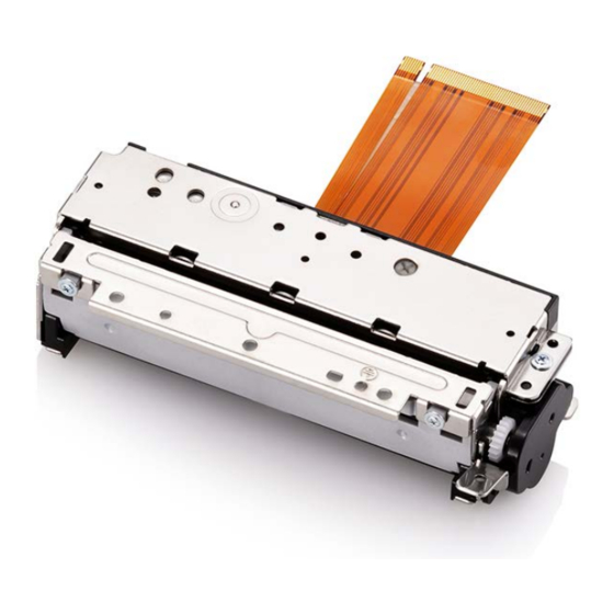
- Page 1 User’s Manual SMP6350 Thermal Printer Mechanism Rev. 2.03 http://www.bixolon.com...
- Page 2 SMP6350 REVISION SHEET Revisions Design section Revision REV. Date Page Description 1.00 27.06.17 K.H.JEON K.H.JEON J.S.LEE Modified TPH and 2.00 14.09.17 K.H.JEON J.S.LEE J.G.KIM 16~29 STEPMOTOR spec. 2.01 20.09.17 K.H.JEON J.S.LEE J.G.KIM 17~23 Modified TPH spec. 42~42 2.02 30.11.17 K.H.JEON J.S.LEE...
-
Page 3: Table Of Contents
SMP6350 ■ Table of Contents 1. Specifications......................14 2. Connector pin arrangement ..................16 2-1 Main FPC cable (50Pin) ..................16 2-2 SUB FPC cable (8Pin) .................... 17 3. Thermal Printer Head ....................18 3-1 Specification ......................18 3-2 Block Diagram of the Head ..................18 3-3 Printing position of transferred data ................ - Page 4 SMP6350 6-3-3 Mounting platen roller block ................44 6-3-4 Precautions during mounting platen roller block ..........46 7. Recommended Placement of Thermal Paper ............47 8. Designing Platen Roller Block Removal Lever ............48 9. Designing Thermal Paper Feed Holder ..............49 10.
- Page 5 Some terms may contain technical terminology of printers. a) Printer mechanism (Mecha) Machanism means SMP6350 which is simply referred to as Mecca in this manual. b) Paper A roll paper that is used to print and is discolored in response to heat.
- Page 6 Please read carefully and fully understand this user’s manual when you design printers or terminals using the printer mechanism (SMP 6350). BIXOLON is not responsible for any damage or loss occurred due to your company’s configuration parts or usage not included in this user’s manual or improper handling of the printer mechanism.
- Page 7 SMP6350 ※ Safety Precautions Take care with the following items when designing products such as terminals using the printer mechanism, and include precautions required for user’s manual so that users of the products such as terminals can use the products safely.
- Page 8 SMP6350 h) Precautions when driving the motor Hair can be rolled into the platen roller and gears when they are closed. Design the control so that the printer driver motor does not operate when the outer case and platen roller block are open. Also, design the outer case so that external objects do not contact the platen roller and gears, so preventing objects from jamming.
- Page 9 SMP6350 ※ Design Precautions Take precautions with the following items when designing products such as terminals using the printer mechanism. a) The sequence of applying power is as follows. - Startup: Apply Logic Power (VDD) and then apply Head supply voltage (VH) - Shutdown: Cut off Head supply voltage (VH) and cut off Logic Power (VDD) b) The head power (VH) must have a TVS diode less than 28V.
- Page 10 SMP6350 l) Noise and vibration during printing may differ depending on the pulse speed of the motor. Check performance by actually using the device. m) Paper feeding force may decrease depending on the pulse speed of the motor. Check performance by actually using the device.
- Page 11 SMP6350 ※ Handling Precautions Incorrect handling of the printer mechanism will reduce the efficiency and damage the system. Precaution must be taken with the following. * When paper other than specified thermal paper is used. - Printing quality may drop due to low thermal sensitivity.
- Page 12 SMP6350 h) When printing at high speed in an environment of low temperature or high humidity, water drops might form on the printer mechanism due to steam generated by the thermal paper and the thermal paper might be damaged. Do not apply power until the water drops are completely dried out.
- Page 13 SMP6350 ■ Characteristics of SMP6350 Printer Mechanism This printer mechanism has the following characteristics. * Integrated cutter - Guillotine-type cutter is included. * High speed printing - Printing speed can be up to 250mm/s printing. * High resolution printing - Smooth and accurate printing using the high-density printing head of 8 dots/mm.
-
Page 14: Specifications
Abrasion resistance : 100km energy) Auto cutter : 1,000,000 cuts Package: Bixolon standard package Impact resistance Height: 75cm Directions: 1 corner, 3edges and 6 surfaces A. TF50KS-E(Paper thickness : 65 µm) of Nippon paper Industries Co., Ltd B. PD 160R(75 µm) of New Oji Paper Mfg, Co., Ltd. - Page 15 SMP6350 Operating conditions For temperature / humidity Printing quality is guaranteed Printer can be operated - 15 - Rev. 2.03...
-
Page 16: Connector Pin Arrangement
SMP6350 2. Connector pin arrangement 2-1 Main FPC cable (50Pin) PIN NO SIGNAL Description P_FEED_AM Feeding motor P_FEED_BM Feeding motor P_FEED_AP Feeding motor P_FEED_BP Feeding motor TPH Ground TPH Ground TPH Ground COVER_IN COVER Sensor Input COVER Sensor Ground COVER_OUT... -
Page 17: Sub Fpc Cable (8Pin)
SMP6350 2-2 SUB FPC cable (8Pin) PIN NO SIGNAL Description CUT_IN Cutter Home Sensor Input CUT_OUT Cutter Home Sensor Output Cutter Home Sensor Ground Cutter Home Sensor Ground C_FEED_AM Cutter Feeding motor C_FEED_AP Cutter Feeding motor C_FEED_BP Cutter Feeding motor... -
Page 18: Thermal Printer Head
SMP6350 3. Thermal Printer Head Thermal head is configured with a thermal device and thermal head drive that drives and controls the thermal device. Data input from the DI terminal is “High” for printing and “Low” for not printing. Data from DI terminals are transferred to the shift registers at the rising edge of the CLK. -
Page 19: Printing Position Of Transferred Data
SMP6350 * Number of strobe dots by TPH manufacturer AOI TPH Block No. Strobe number Heating element number Dots / STB /STROBE1 1 ~ 192 /STROBE2 193 ~ 320 /STROBE3 321 ~ 448 /STROBE4 449 ~ 576 SHEC TPH Block No. -
Page 20: Dimensions Of Thermal Device
SMP6350 3-4 Dimensions of thermal device - 20 - Rev. 2.03... -
Page 21: Electrical Characteristics Of The Thermal Head
SMP6350 3-5 Electrical Characteristics of the Thermal Head Ta = 25℃ ±10°C Item Symbol MIN. TYP. MAX. Umix Remarks Supply voltage 24.0 26.5 4.75 5.25 @ 5.0V Logic voltage @ 3.3V ALL- ㎃ Logic current HIGH 0.7xV @ 5.0V High 0.8xV... -
Page 22: Thermal Head Drive Timing Diagram
SMP6350 3-6 Thermal Head Drive Timing Diagram 3-7 Maximum Condition (Ambient temperature of the printer head: 25℃) Items Maximum condition Condition TPH drive voltage (V 26.4V Include Peak Voltage S.L.T. = 0.50ms Supply Energy (E0) 0.18mJ/dot (at 250mm/s) Temperature detected by Head Temperature (Tmax) 70℃... -
Page 23: Pulse Width Control Of The Head
1) Controlling above the max conditions in upper table causes shorter head life. Please make sure to control it based on the table provided. 2) The head pulse value by temperature in the above conditions is the standard for density of paper recommended by BIXOLON. - 23 - Rev. 2.03... -
Page 24: Thermistor Specifications
SMP6350 3-9-2 Thermistor specifications - Electrical Specifications of Thermistor ▷ Rating 1) Operating temperature: -40 ~ +80 ℃ 2) Time constant: Max. 5 sec (in the air) ▷ Electrical Requirements 30 kΩ ± 5% (at 25℃) 1) Resistance R 2) B value(constant): 3,950 K ± 3% ×EXP(B×(1/T... -
Page 25: Detection Of Abnormal Temperature Of Thermal Head
SMP6350 ※ Recommended Thermistor circuit 10㏀/F 10㏀ 10㏀/F H_TMP TPH Thermistor LM393 4.7kΩ/F 3㏀/F 100㎋ 100㎋ Ground Printer side User side 3-9-3 Detection of abnormal temperature of thermal head In order to protect the thermal head and to guarantee the safety of the user, abnormal temperature of the thermal head must be detected from both hardware and software sides. -
Page 26: Step Motor (Paper Feed)
SMP6350 4. Step Motor (Paper Feed) 4-1 Specifications Item Specifications Type PM type Step Motor Drive method Bi-polar chopper Excitation type 2-2 Phase Terminal voltage DC 21.6V ~ 26.4V Ω/Phase ±10% Wiring resistance Motor control current Max. 0.385A/Phase Motor drive pulse Max 2,003 pps. -
Page 27: Drive Sequence (Motor Rotates In Counterclockwise Direction)
SMP6350 Maximum motor drive time must be limited in order to prevent overheating of the motor. When driving the motor continuously, make sure to conform to the drive ratio (30%). - Maximum drive time: 120 seconds (1601 pps) - Pause time during between maximum drive: 270 seconds... - Page 28 SMP6350 ※ Acceleration step Step Step Step Speed Speed Speed Step Step Step (pps) time (μs) (pps) time (μs) (pps) time (μs) 2,500 1,206 1,658 2,258 1,221 1,669 2,076 1,236 1,681 1,931 1,250 1,689 1,813 1,264 1,701 1,715 1,279 1,712...
-
Page 29: Sensor
SMP6350 5. Sensor 5-1 Paper Detection Sensor and Black Mark Detection Sensor 5-1-1 Absolute maximum rating (Ta = 25℃) Parameter Symbol Rating Unit ㎃ Forward current Input Reverse current ㎽ Power consumption Collector-Emitter voltage VCEO Emitter-Collector Voltage VECO Output ㎃... -
Page 30: Paper Detection Sensor Sample External Circuits
SMP6350 5-1-3 Paper Detection Sensor Sample External Circuits - 3.3V Drive Circuits - 5V Drive Circuits Paper detection Signal level of paper detection sensor (PS_OUT) Paper is detected Paper is not detected High ※ Caution : As the detection voltage difference changes depending on the reference... -
Page 31: Platen Roller Block Detection Switch
SMP6350 5-2 Platen Roller Block Detection Switch - Reference circuit diagram for platen roller block detection 1) 3.3V Drive circuits COS_OUT COS_OUT 2) 5V Drive circuits Platen Roller Block Platen roller block detection sensor signal level Platen Roller Block is detected... -
Page 32: Auto Cutter
SMP6350 5-3 Auto Cutter To cut the paper automatically after printing - Cutting paper: Single layer thermal paper of general paper (Thickness: 50~100㎛) - Rated voltage Motor : DC 24V±5% Current consumption : Max. 0.6A/Phase Sensor : DC 5V±5% - Paper cutting guaranteed life Paper thickness of 65㎛: Cut 1,000,000 times... - Page 33 SMP6350 - Full cut Forward full cut: 137 steps after Sensor OFF Backward full cut: 39 steps after Sensor ON - Partial cut Forward full cut: 98 steps after Sensor OFF Backward full cut: 39 스텝 steps after Sensor ON - 33 - Rev.
-
Page 34: Step Motor (Auto Cutter)
SMP6350 5-4 Step Motor (Auto Cutter) PM type stepping motor Type Bi-polar chopper Drive method 2-2 Phase Excitation method DC 21.6V~26.4V Motor drive voltage 8.5 Ω/Phase ±10% Wiring resistance Max. 0.6A/Phase Motor control current Max.1,172pps Motor drive pulse 5-4-1 Auto Cutter Drive Circuits - 3.3V Drive Circuits... -
Page 35: Auto Cutter Sensor(Home Sensor)
SMP6350 5-4-2 Auto Cutter Sensor(Home Sensor) - Absolute max. ratings. (Ta = 25℃) Parameter Symbol Rating Unit ㎃ Forward current Input Reverse voltage (LED) ㎽ Power dissipation Collector-emitter voltage Collector-emitter voltage Output ㎃ (Photo-TR) Collector current ㎽ Collector power dissipation ℃... - Page 36 SMP6350 - Sensor Drive Circuit ※ Caution Auto Cutter sensor can cause chattering by circuit operating characteristic. Chattering protection circuit (hardware) or program (software) is compulsory. *1 The number of corrective action increase may lead sensor recognition time delay which results in cutting issues. Measure the cutter sensor raise/lower signal to determine the number of corrective actions for the cutter motor to operate within 2Setp.
-
Page 37: Auto Cutter Flow Chart
SMP6350 5-4-3 Auto Cutter Flow Chart Cutter Execution Command Cutter_ Sensor = H*1) Backward 1 Step, Step_ Counter++ Forward 1 Step, Step_ Counter++ If Step_ Counter > 50, Cutter Error Cutter_ Sensor H*1) Cutter_ Switch = L *1) Backward 39 Steps... -
Page 38: Acceleration Step
SMP6350 5-4-4 Acceleration Step Step Step Step Speed Speed Speed Step Step Step (pps) time (μs) (pps) time (μs) (pps) time (μs) 2,500 1,302 1,010 2,326 1,276 1,022 2,179 1,250 1,034 2,058 1,225 1,047 1,957 1,203 1,059 1,869 1,182 1,070... -
Page 39: Case Design
SMP6350 6. Case Design 6-1 Mounting Position 6-1-1 Method of mounting the printer mechanism The figure below shows the dimensions required to position and fix the printer mechanism. Fixed the printer firmly by applying a Hook feature to the front, such as SECTIOIN B-B' Go ahead. - Page 40 SMP6350 Fig 6-2 How to mount the mechanism on the hook - 40 - Rev. 2.03...
- Page 41 SMP6350 Fig 6-3 Dimension related to mounting - 41 - Rev. 2.03...
-
Page 42: Recommended Screws
SMP6350 6-1-2 Recommended Screws - JIS B1111 M2.6 Cross Fluted Pan Head Machine Screw 6-1-3 Precautions during mounting the printer body - Care must be taken not to make excessive impact, deformation, or twist while mounting the printer. Otherwise, it might cause degradation of printing quality, paper tilting, paper jam, or printing noise. -
Page 43: Installation Of Platen Roller Block
SMP6350 6-3 Installation of Platen Roller Block 6-3-1 Pivot center area of platen roller block The platen roller block can be mounted in the area between min 50 mm and max 200 mm from the outer case, and the installation area depends on the distance. -
Page 44: Parallel Design Of The Platen Roller Block
SMP6350 6-3-2 Parallel design of the platen roller block When the platen roller block is mounted on the printer mechanism, two blocks must be aligned to be parallel. Otherwise it might cause cutting failure and reduce life of cutter. Check performance after installation. - Page 45 SMP6350 - Holes at ‘a 2’ positions are for setting the position of the platen roller block, design the boss for these two holes. The size and height of the boss shall be within Φ2, and1.2mm respectively. - Holes at ‘b 3’ positions are for fixing the platen roller block using screws(M2.6).
-
Page 46: Precautions During Mounting Platen Roller Block
SMP6350 6-3-4 Precautions during mounting platen roller block - The outer case that the platen roller block is mounted on must be designed to have sufficient strength to avoid impact, twist, deformation by external force, or moving, and the pivot axis for mounting the outer case must be designed to have no slack in front and back or left and right direction. -
Page 47: Recommended Placement Of Thermal Paper
SMP6350 7. Recommended Placement of Thermal Paper Design the path of the paper in printer mechanism as shown in Fig 9-1 Design the paper path angle within a range of 30 degrees, as shown in the drawing below. The larger the paper path angle, the significantly reduced paper feed force on the printer and the result of paper feed fail. -
Page 48: Designing Platen Roller Block Removal Lever
SMP6350 8. Designing Platen Roller Block Removal Lever The following Fig 8-1 shows the operating area position of the platen roller block removal lever. Fig 8-1 Dimensions related to the operation of the platen roller block removal lever Take precautions with the following while designing lever or button for removing the platen roller block. -
Page 49: Designing Thermal Paper Feed Holder
SMP6350 9. Designing Thermal Paper Feed Holder - Design the paper feed hold so that the feeding load of the paper becomes lower than 0.98N (100gf). Design additional devices to meet the requirements of paper load. Feed load bigger than 0.98N may cause a printing defect or paper feed failure. Conduct sufficient verification by actually using the device. -
Page 50: Designing The Device To Release The Jamming Of Moving Blade
SMP6350 10. Designing the device to release the jamming of moving blade When the power is off while the moving blade is in a forward position or when moving blade is used manually, the moving blade may be jammed with the fixed blade causing problems in releasing the platen roller block. -
Page 51: Thermal Paper Exit Design
SMP6350 11. Thermal Paper Exit Design Take the following precautions when designing the paper exit Fig 11-1 Dimensions related to the paper exit - Secure enough space so that paper exit is free from external force during printing. Among the dimensions shown in Fig 11-1, especially incorrect dimension about 4 +0.5 ,0 may cause problems such as shortening the life of cutter or paper jam,... -
Page 52: Precautions For Outer Case Design
SMP6350 12. Precautions for Outer Case Design - Fixed cutter blade in the platen roller block will be exposed when installing the printer mechanism. People may be injured by the fixed cutter blade during operation of the cutter or replacing thermal paper. In order to prevent accidental injury, install the structure on the outer case or attach a warning label. -
Page 53: Frame Ground
SMP6350 13. Frame Ground It is advisable to connect the printer body and the platen roller block to the FG (frame ground) of the outer case to prevent damage to the thermal head by static electricity. Check performance by actually using the device. -
Page 54: Printer Mechanism Handling Method
SMP6350 14. Printer Mechanism Handling Method 14-1 Installation of thermal paper - Press the platen roller block release lever of the printer mechanism. - Install thermal paper at the correct position between the paper guide device of the printer mechanism, and put the tip of the thermal paper upward by more than two inches (about 5 cm). -
Page 55: Precautions When Installing/Removing Thermal Paper
SMP6350 14-5 Precautions when installing/removing thermal paper - Automatic loading may not work if the thermal head touches the platen roller for a long time without thermal paper as they might get stuck together. If this problem occurs, remove the platen roller block and install it again. -
Page 56: Appearance And Dimensions
SMP6350 15. Appearance and Dimensions - Assembly (Excluding Platen Roller Block) - 56 - Rev. 2.03... - Page 57 SMP6350 - Assembly (Including Platen Roller Block) - 57 - Rev. 2.03...
- Page 58 SMP6350 - Platen Roller Block - 58 - Rev. 2.03...
-
Page 59: Product Approval Sheet
SMP6350 ※ 제품 승인원 ※ Product Approval Sheet Product Name SMP6350 Manufacturer BIXOLON Product SMP6350 User’s Manual Rev.2.03 Specifications Customer Approved Date Approver Signature - 59 - Rev. 2.03...
Need help?
Do you have a question about the SMP6350 and is the answer not in the manual?
Questions and answers