Advertisement
Quick Links
LUXOMAT
Montage-Anleitung
DE
Vorbereitung
Arbeiten an elektrischen Anlagen
!
dürfen nur von Elektrofachkräf-
ten oder von unterwiesenen
Personen unter Leitung und
Aufsicht einer Elektrofachkraft
entsprechend den elektrotechni-
schen Regeln vorge nommen
werden.
Vor Montage Leitung spannungs-
!
frei schalten!
Dieses Gerät ist nicht zum
!
Freischalten geeignet.
DALI ist nicht SELV – Es gelten die
!
Installationsvorschriften für
Niederspannung.
Die DALI-Schraubklemmen dür-
!
fen nicht an 230 VAC angeschlos-
sen werden!
Funktionsweise
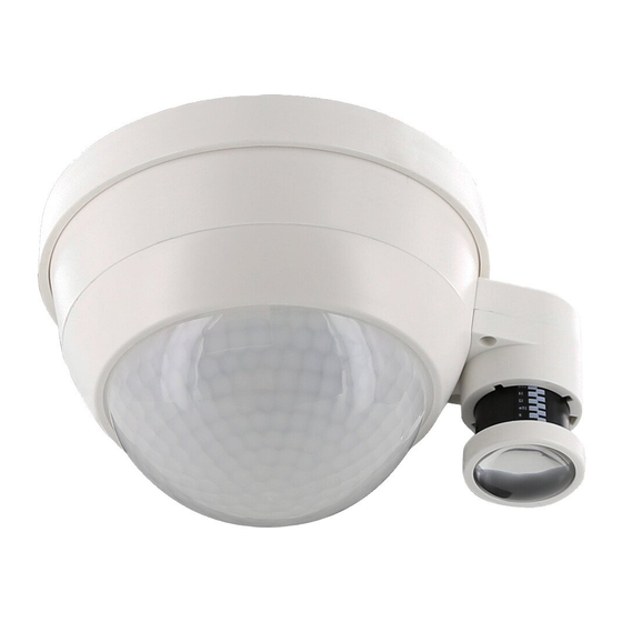
Adressierbarer DALI-Multisensor
zur Aufputzmontage.
Stromversorgung über DALI-Bus.
Addressier- und nutzbar gemäß IEC
62386 Teil 103 (Steuergerät). Instanz 0
stellt Informationen bezüglich Raum-
belegung und Bewegungserkennung
gemäß IEC 62386 Teil 303 am DALI-
Bus bereit. Instanz 1 stellt LUX Werte
gemäß IEC 62386 Teil 304 am DALI-Bus
bereit. Parametrierung ist über einen
erforderlichen Multimaster-Appli-
kations-Controller eines beliebigen
Herstellers möglich. Dieser Controller
muss IEC 62386 Teil 101/103/303/304
unterstützen.
Montage
Индикаторы
LED
закрыть
открыть
Fig. 3
Selbstprüfzyklus
In den ersten 20s nach Zuführung
der DALI-Bus-Spannung durchläuft
der Melder einen Selbstprüfzyklus. In
dieser Zeit reagiert das Gerät nicht auf
Bewegung.
Inbetriebnahme
Allgemein: Das Gerät kann nach der
Montage direkt und gemäß der An-
leitung der zur Verfügung gestellten
Software des jeweiligen Control-
ler-Herstellers in Betrieb genommen
werden.
net PD4-BMS
®
Mounting-Instructions
GB
Preparations
Work on the mains supply may
!
only be carried out by qualified
professionals or by instructed
persons under the direction and
supervision of qualified skilled
electrical personnel in accord-
ance with electrotechnical
regulations.
Disconnect supply before
!
installing!
This device is not to be used to
!
isolate other equipment from the
mains supply.
DALI is not SELV – the installation
!
instructions for low voltage apply
The DALI screw clamps must not
!
be connected to 230 VAC!
Operation
Adressable DALI multisensor
designed for surface mounting.
Powered via DALI bus. Addressable
according to IEC 62386 Part 103
(control device). Instance 0 provides
information regarding occupancy
and movement for the DALI bus
according to IEC 62386 part 303.
Instance 1 provides LUX values for the
DALI bus according to IEC 62386 part
304. Parameterisation is possible via
mandatory Multimaster-Application-
Controller of any manufacturer. This
controller must support IEC 62386
parts 101/103/303/304.
Mounting
N1234
1234
Код продукции
Self-test cycle
During the first 20 sec after connecti-
on to the DALI bus power, the product
will enter a self-test cycle. During this
time the device does not respond to
movement.
Initial operation
General: The device can be put into
service directly after mounting, follo-
wing the software instructions from
the relevant controller manufacturer.
Montage - Instructions
FR
Preparation du montage
Travailler sur le réseau électrique
!
ne s'improvise pas, seul un
electricien qualifié et habilité
doit effectuer ce raccordement.
Avant de commencer
!
l'installation, assurez-vous que
l'alimentation est coupée.
Cet appareil ne doit pas être utilisé
!
pour isoler d'autres appareils de
l'alimentation secteur.
DALI est différent de SELV – Les
!
prescriptions d'installation pour
basse tension doivent être
respectées.
Les bornes DALI ne doivent pas
!
être raccordées au 230 VCA!
Fonctionnement
Multicapteur DALI adressable pour
montage apparent.
Alimentation par bus DALI. Adressable
et utilisable selon IEC 62386 Partie
103 (unité de commande). La section
0 fournit des informations sur la
détection de mouvements sur le bus
DALI selon IEC 62386 partie 303. La
section 1 fournit les valeurs LUX sur le
bus DALI selon IEC 62386 partie 304. Le
paramétrage est possible par l´inter-
médiaire d´un contrôleur d´application
multi-maîtres provenant de n'importe
quel fabricant. Ce contrôleur doit être
compatible avec la norme IEC 62386
partie 101/103/303/304.
Montage
Fig. 2
Cycle d'autocontrôle
Au cours des premières 20 s après la
connexion au bus DALI, le détecteur
procède à un cycle d'autocontrôle.
Durant cette période, l'appareil ne
réagit pas aux mouvements.
Opération initiale
Général : L'appareil peut être mis en
service directement après le montage
et conformément à la notice du logiciel
du fabricant de contrôleur mise à
disposition.
93325
Инструкция к монтажу
RU
Работы с сетью могут
!
выполняться только
квалифицированными
специалистами или обученными
лицами под руководством и
контролем квалифицированного
электротехнического персонала в
соответствии с электро-
техническими правилами.
Отключите питание перед
!
установкой!
Данное устройство не подходит
!
для безопасного отключения
электросети
DALI не является SELV -
!
используйте инструкции по
работе с низким напряжением
!
Не подключайте зажимы DALI к
источнику напряжения
Эксплуатация
Адресный мультисенсор DALI
для накладного монтажа.
Питание по шине DALI
технология DALI мультимастер в
соответствии с IEC 62386 часть 103
Статус 0 передает в шину DALI
информацию о присутствии и
движении в соответствии с IEC 62386
часть 303. Статус 1 передает в шину
DALI значение освещенности в
соответствии со спецификацией IEC
62386 часть 304. Параметризация
возможна только через сторонние
контроллеры DALI. Эти контроллеры
должны поддерживать спецификацию
IEC 62386 части 101/103/303/304.
Монтаж
Fig. 1
2
3
1
1
2
3
2.50 m
Ø 24.00 m Ø 8.00 m
Ø 6.40 m
5.00 m
Ø 48.00 m Ø 16.00 m
–
Самотестирование
При первом подключении(в течение
20сек) к шине DALI устройство
входит в режим самотестирования. В
это датчик не реагирует на
движения..
Ввод в эксплуатацию
Устройство может быть введено в
сервисный режим после установки.
Следуйте инструкции от
производителя
Advertisement

Related Manuals for B.E.G. LUXOMAT PD4-BMS


Summary of Contents for B.E.G. LUXOMAT PD4-BMS
- Page 1 93325 net PD4-BMS LUXOMAT ® Montage-Anleitung Mounting-Instructions Montage - Instructions Инструкция к монтажу Vorbereitung Preparations Preparation du montage Arbeiten an elektrischen Anlagen Work on the mains supply may Travailler sur le réseau électrique Работы с сетью могут dürfen nur von Elektrofachkräf- only be carried out by qualified ne s’improvise pas, seul un выполняться...
- Page 2 Ограничение зоны Exclusion des sources de Ausgrenzen von Exclude sources of обнаружения pertubation Störquellen interference Falls der Erfassungsbereich des In case the detection area of the Si la portée de détection est trop В случае если зона обнаружения Melders zu groß ist oder Bereiche detector is too large or areas are grande ou couvre des zones qui датчика...
- Page 3 Schaltbild Wiring diagram Schéma de câblage Схема подключения Schematisches Schaltbild – Bitte Schematic diagram - when connecting Schéma de raccordement de base – При подключении датчика, beachten Sie beim Anschließen die the detector, please respect the veuillez respecter le marquage des bornes соблюдайте...
- Page 4 Brück Electronic GmbH B.E.G. г. Москва, ул. Малая Ордынка, д. 39, стр. 1 Телефон: 8 (499) 236 10 67 E-Mail: info@beg-russia.ru Internet: www.beg-russia.ru...
Need help?
Do you have a question about the LUXOMAT PD4-BMS and is the answer not in the manual?
Questions and answers