RKI Instruments 65-2330RK Operator's Manual
Hydrogen sulfide transmitter
Hide thumbs
Also See for 65-2330RK:
- Operator's manual (20 pages) ,
- Operator's manual (20 pages) ,
- Operator's manual (20 pages)

Related Manuals for RKI Instruments 65-2330RK


Summary of Contents for RKI Instruments 65-2330RK
- Page 1 65-2330RK Hydrogen Sulfide Transmitter Operator’s Manual Part Number: 71-0197RK Revision: A Released: 6/11/20 RKI Instruments, Inc. www.rkiinstruments.com...
- Page 2 Typical calibration frequencies for most applications are between 3 and 6 months, but can be required more often or less often based on your usage. 2 • 65-2330RK H S Transmitter...
- Page 3 Product Warranty RKI Instruments, Inc. warrants gas alarm equipment sold by us to be free from defects in materials, workmanship, and performance for a period of one year from date of shipment from RKI Instruments, Inc. Any parts found defective within that period will be repaired or replaced, at our option, free of charge.
-
Page 4: Table Of Contents
Parts List ..............20 4 • 65-2330RK H... -
Page 5: Overview
Operating Temperature -40°F to 104°F (-40°C to 40°C) WARNING: When using the 65-2330RK, you must follow the instructions and warnings in this manual to assure proper and safe operation of the 65-2330RK and to minimize the risk of personal injury. Be sure to maintain and periodically calibrate the 65-2330RK as described in this manual. -
Page 6: Description
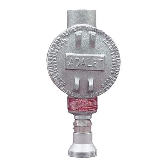
Factory Adjust Pot Span Pot Zero Pot Amplifier Detector Terminal Strip + Test Point (Red) 100 mV - 500 mV Range - Test Point (Black) J-Box H2S Detector Figure 1: H S Transmitter Component Location 6 • 65-2330RK H S Transmitter... -
Page 7: H 2 S Detector
The sensor is secured within the detector assembly by the housing cap. Through a series of chemical and electrical reactions, the sensor produces an electrical output that corresponds to the detection range of the transmitter. 65-2330RK H S Transmitter • 7... -
Page 8: Amplifier
Use the top 3/4 NPT conduit hub to connect wiring from the amplifier to the controller. Use the cover on the front of the junction box to access the interior of the junction 8 • 65-2330RK H S Transmitter... -
Page 9: Installation
Select a site that is at normal breathing level. 3.10 3/4 NPT Female 3.65 6.8 Max Rubber Spacers J-Box H2S Detector 1 1 /2-20 T hread for Calibration Cup Figure 3: Mounting the H S Transmitter 65-2330RK H S Transmitter • 9... -
Page 10: Wiring The H S Transmitter To A Controller
S transmitter through one of the conduit hubs at the controller housing. CAUTION:Do not route power and transmitter wiring through the same controller conduit hub. The power cable may disrupt the transmission of the transmitter signal to the controller. 10 • 65-2330RK H S Transmitter... -
Page 11: Startup
Introducing Incoming Power 1. Complete the installation procedures described earlier in this manual. 2. Verify that the power wiring to the controller is correct and secure. Refer to the controller operator’s manual. 65-2330RK H S Transmitter • 11... -
Page 12: Setting The Zero Signal
The procedure below describes applying zero emission air, usually called zero air, using a calibration kit that includes a calibration cup, calibration gas, sample tubing, and a fixed flow regulator with an on/off knob. RKI Instruments, Inc. recommends using a 0.5 LPM (liters per minute) fixed flow regulator. -
Page 13: Maintenance
6. If the fail condition continues, misconnected. contact RKI for further instruction. • The transmitter’s zero reading is low enough to cause a fail condition. • The transmitter is malfunctioning. 65-2330RK H S Transmitter • 13... -
Page 14: Replacing Components Of The H S Transmitter
5. Remove the replacement sensor from its packaging and remove the wire jumper. This wire jumper is installed on the sensor pins for shipment or storage but must be removed for the sensor to operate properly when installed in a detector. 14 • 65-2330RK H S Transmitter... - Page 15 8. Connect the detector leads to the appropriate detector terminal strip terminals. Connect the red wire to the terminal labeled TOXIC + and the black wire to the terminal labeled TOXIC -. See Figure 4 for the detector wiring connections to the amplifier. 65-2330RK H S Transmitter • 15...
- Page 16 Make sure the amplifier is seated flat in the junction box. 8. Install the new amplifier into the junction box with the screw, lock washer, and flat washer you removed in Step 5. 16 • 65-2330RK H S Transmitter...
-
Page 17: Calibration Frequency
Although there is no particular calibration frequency that is correct for all applications, a calibration frequency of every 3 months is adequate for most H S transmitter applications. Unless experience in a particular application dictates otherwise, RKI Instruments, Inc. recommends a calibration frequency of every 3 months for the H S transmitter. -
Page 18: Calibration
It describes the test using a calibration kit that includes a calibration cup, calibration gas, sample tubing, and a fixed flow regulator with an on/off knob. RKI Instruments, Inc. recommends using a 0.5 LPM (liters per minute) fixed flow regulator. -
Page 19: Setting The Response Reading
4. When the display reading falls below the alarm setpoints, return the controller to normal operation. 5. Verify that the controller display reading decreases and stabilizes at 0 ppm. 6. Store the components of the calibration kit in a safe and convenient place. 65-2330RK H S Transmitter • 19... -
Page 20: Parts List
(cylinders with external threads) 81-1051RK Regulator with gauge and knob, 0.5 LPM, for 34 liter aluminum, 58 liter, and 103 liter calibration cylinders (cylinders with internal threads) 81-1117RK Calibration cup ES-1537-H2S S replacement sensor 20 • 65-2330RK H S Transmitter...
Need help?
Do you have a question about the 65-2330RK and is the answer not in the manual?
Questions and answers