
Related Manuals for RKI Instruments 65-2396RKSS Series


Summary of Contents for RKI Instruments 65-2396RKSS Series
- Page 1 65-2396RKSS Transmitter Operator’s Manual Part Number: 71-0338 Revision: 0 Released: 9/1/20 RKI Instruments, Inc. www.rkiinstruments.com...
- Page 2 WARNING Read and understand this instruction manual before operating transmitter. Improper use of the transmitter could result in bodily harm or death. Periodic calibration and maintenance of the transmitter is essential for proper operation and correct readings. Please calibrate and maintain this transmitter regularly! Frequency of calibration depends upon the type of use you have and the sensor types.
- Page 3 Product Warranty RKI Instruments, Inc. warrants gas alarm equipment sold by us to be free from defects in materials, workmanship, and performance for a period of one year from date of shipment from RKI Instruments, Inc. Any parts found defective within that period will be repaired or replaced, at our option, free of charge.
-
Page 4: Table Of Contents
Table of Contents Overview ..............5 Specifications . -
Page 5: Overview
Overview This manual describes the 65-2396RKSS CO transmitter. This manual also describes how to install, start up, configure, maintain, and calibrate the transmitter when it is used with a gas monitoring controller. A parts list at the end of this manual lists replacement parts and accessories for the CO transmitter. -
Page 6: Description
Description This section describes the components of the CO transmitter. The transmitter is a 4 - 20 mA type detector head. It consists of the CO detector, amplifier, and junction box. Controller Terminal Factory Adjust Pot Strip Span Pot Zero Pot Amplifier Factory Adjust Pot Jumper Pins,... -
Page 7: Amplifier
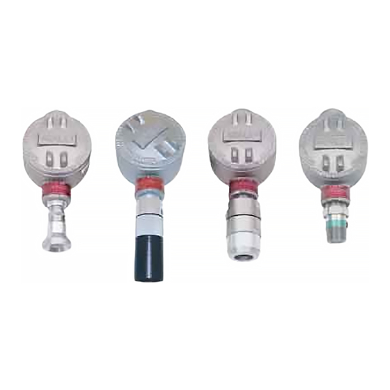
To distinguish the different ranges of CO detectors from one another, a short length of shrink tubing is applied to the wiring where it comes out of the nipple. The following table indicates the color of the shrink tubing and the color of the wire to which it is applied. Table 2:CO Detector Color Designations Detector... -
Page 8: Junction Box
CAUTION: The amplifier includes two additional potentiometers. They are factory-set. Do not adjust them. Test Points The test points are on the left side of the amplifier (see Figure 1). The test points produce a 100 mV to 500 mV output that corresponds to the transmitter’s 4 to 20 mA output. Use the test points and a voltmeter to measure the amplifier’s output during the start-up and calibration procedures. -
Page 9: Wiring The Co Transmitter
3.66 3.15 3/4 NPT Female, 2X 3.34 .20 Dia. x .45 Slot, 2X 6.80 MAX J-Box IR CO2 Detector Figure 2: Mounting the CO Transmitter 2. At the monitoring site you select, hang or mount the junction box with the detector facing down (see Figure 2). - Page 10 WARNING: To maintain the explosion proof classification of the CO detector/junction box combination, a conduit seal must be used within 18 inches of the junction box conduit hub used for wiring to the controller. Adhere to your local electrical code when installing the conduit seal.
- Page 11 + 24 VDC Install conduit seal 4 - 20 mA In (S) within 18 inches - (DC Ground) Cable Shield J-Box Controller Amplifier Black Green Detector W ires White IR CO2 Detector Figure 3: Wiring the CO Transmitter to a Controller 12.
-
Page 12: Startup
Start Up This section describes procedures to start up the CO transmitter and place the transmitter into normal operation. Introducing Incoming Power 1. Complete the installation procedures described earlier in this manual. 2. Verify that the power wiring to the controller is correct and secure. Refer to the controller operator’s manual. -
Page 13: Maintenance
7. Turn the regulator’s on/off knob counterclockwise to open it. Gas will begin to flow. 8. Allow the gas to flow for one minute. 9. Verify a voltmeter reading of 100 mV (±2 mV). 10. If necessary, use a small flat-blade screwdriver to adjust the zero pot until the voltmeter reading is 100 mV (±2 mV). -
Page 14: Troubleshooting
Troubleshooting The troubleshooting guide describes symptoms, probable causes, and recommended action for problems you may encounter with the CO transmitter. NOTE: This troubleshooting guide describes transmitter problems only. See the controller operator’s manual for problems you may encounter with the controller. Table 3:Troubleshooting the CO Transmitter Condition... - Page 15 5. Disconnect the detector leads from the detector terminal strip. Note the position of the color-coded leads as you remove them. 6. Unscrew the detector from the junction box. 7. Guide the detector leads of the replacement detector through the bottom conduit hub of the junction box, then screw the mounting threads of the detector into the conduit hub.
- Page 16 6. Remove the old amplifier. 7. Place the new amplifier in the same position as the old amplifier. A foam gasket that orients the amplifier and keeps it from rotating is installed on the bottom of the amplifier. Make sure the amplifier is seated flat in the junction box.
-
Page 17: Calibration Frequency
6 months is adequate for most infrared CO transmitter applications. Unless experience in a particular application dictates otherwise, RKI Instruments, Inc. recommends a calibration frequency of every 6 months. If an application is not very demanding, for example detection in a clean, temperature controlled environment where calibration adjustments are minimal at calibration, then a calibration frequency of every 9 to 12 months is adequate. -
Page 18: Setting The Zero Reading
NOTE: Calibrating the CO transmitter may cause alarms. Be sure to put the controller into its calibration mode or disable external alarms before continuing. Setting the Zero Reading Since there is a background of CO in air of typically 300 - 600 ppm (0.03 - 0.06% volume), it is necessary to use a calibration kit with a 100% nitrogen cylinder to set the zero signal of a CO transmitter with a low range detector. -
Page 19: Parts List
Parts List Table 7 lists replacement parts and accessories for the CO transmitter. Table 7:Parts List Part Number Description 06-1248RK Sample tubing (3/16 in. x 5/16 in.; specify length when ordering) 10-5153RK Lid locking set screw 18-0416RK-11 Junction box with cover, stainless steel 57-1053RK Amplifier with gasket (specify detector part number when ordering) 61-0191RK-01... - Page 20 Table 7:Parts List Part Number Description 81-0072RK-01 Calibration cylinder, 2.5% CO , 34 liter steel 81-0073RK-01 Calibration cylinder, 15% CO , 34 liter steel 81-0078RK-01 Calibration cylinder, 100% nitrogen, 34 liter steel 81-1050RK Regulator, with gauge and knob, 0.5 liter/minute continuous flow, for 17 liter and 34 liter steel calibration cylinders (cylinders with external threads) 81-1051RK Regulator, with gauge and knob, 0.5 liter/minute continuous flow, for 34 liter...
Need help?
Do you have a question about the 65-2396RKSS Series and is the answer not in the manual?
Questions and answers