
Related Manuals for RKI Instruments 65-2390RK


Summary of Contents for RKI Instruments 65-2390RK
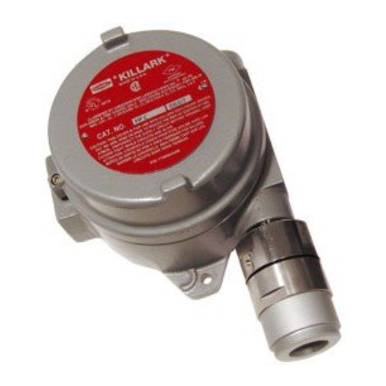
- Page 1 65-2390RK Combustible Gas Transmitter Operator’s Manual Part Number: 71-0119RK Revision: P1 Released: 4/14/06 www.rkiinstruments.com...
- Page 2 Product Warranty RKI Instruments, Inc., warrants gas alarm equipment sold by us to be free from defects in materials, workmanship, and performance for a period of one year from date of shipment from RKI Instruments, Inc. Any parts found defective within that period will be repaired or replaced, at our option, free of charge.
-
Page 3: Table Of Contents
Parts List ..............18 65-2390RK Combustible Gas Transmitter • 3... -
Page 4: Overview
Overview This manual describes the 65-2390RK combustible gas transmitter. This manual also describes how to install, start up, configure, maintain, and calibrate the transmitter when it is used with a gas monitoring controller. A parts list at the end of this manual lists replacement parts and accessories for the combustible gas transmitter. -
Page 5: Description
Description The 65-2390RK combustible gas transmitter has two versions, the 65-2390RK-CH4 which is calibrated to methane and the 65-2390RK-HC which is calibrated to propane. The transmitter utilizes an infrared type of detector which has some advantages over a catalytic type of combustible detector. The infrared detector will generally have a longer... -
Page 6: Amplifier
Use the junction box’s two mounting holes to mount the combustible gas transmitter to a vertical surface at the monitoring site. Use the cover on the front of the junction box to access the interior of the junction box. 6 • 65-2390RK Combustible Gas Transmitter... -
Page 7: Installation
Screw the detector into the bottom conduit hub of the junction box. At the monitoring site, use #10 screws through the junction box’s two mounting holes to secure the junction box to a vertical surface. 65-2390RK Combustible Gas Transmitter • 7... -
Page 8: Wiring The Combustible Gas Transmitter
CAUTION: Do not route power and transmitter wiring through the same conduit hub. The power cable may disrupt the transmission of the transmitter signal to the controller. Connect the wires to the applicable transmitter terminal strip at the controller as shown in Figure 3 below. 8 • 65-2390RK Combustible Gas Transmitter... - Page 9 Cable Shield Controller Transmitter Terminals,Typical 4-20 Figure 3: Wiring the Combustible Gas Transmitter to a Controller 10. If shielded cable is used, connect the cable’s drain wire to an available chassis ground at the controller. 65-2390RK Combustible Gas Transmitter • 9...
-
Page 10: Startup
Verify a voltmeter reading of 100 mV (±2 mV). If necessary, use a flat-blade screwdriver to adjust the zero potentiometer until the voltmeter reading is 100 mV (±2 mV). Secure the junction box cover to the junction box. 10 • 65-2390RK Combustible Gas Transmitter... -
Page 11: Maintenance
Remove the junction box cover, then plug the voltmeter leads into the test points on the amplifier. Plug the positive lead into the test point labeled TP+ ; plug the negative lead into the test point labeled TP- . 65-2390RK Combustible Gas Transmitter • 11... - Page 12 10. When the controller display reading falls below the alarm setpoints, return the controller to normal operation. 11. Store the components of the calibration kit in a safe place. Biannually Calibrate the combustible gas transmitter as described in “Calibration” on page 16 of this manual. 12 • 65-2390RK Combustible Gas Transmitter...
-
Page 13: Troubleshooting
4. If the calibration/response difficulties • Transmitter requires continue, contact RKI for further frequent calibration. instruction. Note: Under “normal” circumstances, the transmitter requires calibration once every six months. Some applications may require a more frequent calibration schedule. 65-2390RK Combustible Gas Transmitter • 13... -
Page 14: Replacing Components Of The Combustible Gas Transmitter
Unscrew and remove the two screws that secure the amplifier to the junction box. The screws are at the top left and bottom right of the amplifier. Remove the amplifier. 14 • 65-2390RK Combustible Gas Transmitter... - Page 15 13. Turn on the controller and place it into normal operation. CAUTION: Allow the detector to warm up for 5 minutes before you continue with the next step. 14. Calibrate the combustible gas transmitter as described in “Calibration” on page 16 of this manual. 65-2390RK Combustible Gas Transmitter • 15...
-
Page 16: Calibration Frequency
6 months is adequate for most infrared combustible gas transmitter applications. Unless experience in a particular application dictates otherwise, RKI Instruments, Inc. recommends a calibration frequency of every 6 months for the infrared combustible gas transmitter. -
Page 17: Setting The Zero Reading
When the display reading falls below the alarm setpoints, return the controller to normal operation. Verify that the controller display reading decreases and stabilizes at 0%LEL. Store the components of the calibration kit in a safe and convenient place. 65-2390RK Combustible Gas Transmitter • 17... -
Page 18: Parts List
Methane transmitter (includes detector, junction box, and amplifier) 65-2390RK-HC Propane transmitter (includes detector, junction box and amplifier) 71-0119RK 65-2390RK Combustible Gas Transmitter Operator’s Manual (this document) 81-0004RK-01 Calibration cylinder (50% LEL propane; 34-liter) 81-0012RK-01 Calibration cylinder (50% LEL Methane; 34-liter)
Need help?
Do you have a question about the 65-2390RK and is the answer not in the manual?
Questions and answers