
Related Manuals for RKI Instruments 65-2340RK


Summary of Contents for RKI Instruments 65-2340RK
- Page 1 65-2340RK Toxic Gas Transmitter Operator’s Manual Part Number: 71-0143RK Revision: G Released: 6/12/20 RKI Instruments, Inc. www.rkiinstruments.com...
- Page 2 Typical calibration frequen- cies for most applications are between 3 and 6 months, but can be required more often or less often based on your usage. 2 • 65-2340RK Toxic Gas Transmitter...
- Page 3 Product Warranty RKI Instruments, Inc. warrants gas alarm equipment sold by us to be free from defects in materials, workmanship, and performance for a period of one year from date of shipment from RKI Instruments, Inc. Any parts found defective within that period will be repaired or replaced, at our option, free of charge.
-
Page 4: Table Of Contents
Parts List ............. 21 4 • 65-2340RK Toxic Gas Transmitter... -
Page 5: Overview
The 65-2340RK toxic gas transmitter can be used for various target gases which are listed in Table 1 below. For a particular target gas, the part number of the toxic transmitter will be of the format 65-2340RK-XXX. -
Page 6: Description
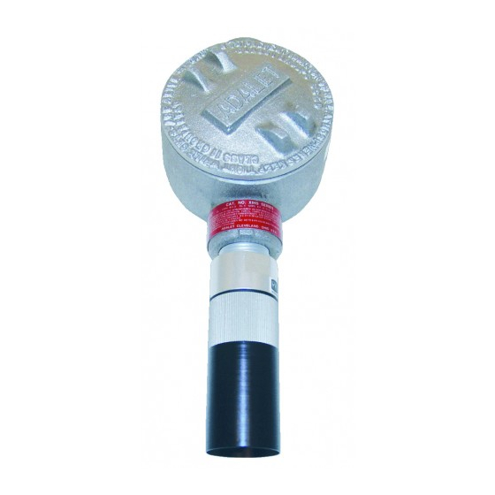
This section describes the components of the toxic gas transmitter. The toxic gas transmitter is a 4 - 20 mA type detector head. It consists of the toxic detector, amplifier, and junction box. Amplifier J-Box Toxi c Detector Figure 1: Toxic Transmitter Component Location 6 • 65-2340RK Toxic Gas Transmitter... -
Page 7: Toxic Detector
Plug-In Sensor The plug-in sensor is secured in the detector assembly by the housing cap. There is a different sensor for each target gas. Through a series of chemical and electrical reactions, the sensor 65-2340RK Toxic Gas Transmitter • 7... -
Page 8: Amplifier
(fresh air) output during the start-up and calibration procedures. Turn the adjustment screw clockwise to increase the zero output and counterclockwise to decrease the zero output. 8 • 65-2340RK Toxic Gas Transmitter... -
Page 9: Junction Box
Select a site where the transmitter is not likely to be bumped or disturbed. Make sure there is sufficient room to perform start-up, maintenance, and calibration procedures. • Select a site where the target gas is likely to be found first. 65-2340RK Toxic Gas Transmitter • 9... - Page 10 Spacer, 3X 9.60 Max Junction Toxic Detector Figure 4: Mounting the Toxic Gas Transmitter 2. At the monitoring site you select, hang or mount the junction box with the detector facing down (see Figure 4). 10 • 65-2340RK Toxic Gas Transmitter...
-
Page 11: Wiring The Toxic Gas Transmitter
CAUTION:Do not route power and transmitter wiring through the same controller conduit hub. The power cable may disrupt the transmission of the transmitter signal to the controller. 11. Connect the wires to the applicable detector/transmitter terminal strip at the controller as shown in Figure 5. 65-2340RK Toxic Gas Transmitter • 11... - Page 12 12. If shielded cable is used, connect the cable’s drain wire to an available chassis (earth) ground at the controller. RKI controllers typically have a ground stud that can be used to ground the cable’s drain wire. 12 • 65-2340RK Toxic Gas Transmitter...
-
Page 13: Startup
6. If necessary, use a small flat-blade screwdriver to adjust the zero pot until the voltmeter reading is 100 mV (±2 mV). 7. Remove the voltmeter leads from the test points. 8. Secure the junction box cover to the junction box. 65-2340RK Toxic Gas Transmitter • 13... -
Page 14: Maintenance
5. If the fail condition continues, condition. contact RKI for further instruction. • The transmitter is malfunctioning. 14 • 65-2340RK Toxic Gas Transmitter... -
Page 15: Replacing Components Of The Toxic Gas Transmitter
3. Unscrew the detector housing cap with the splashguard from the detector housing body. Make sure not to lose the cap gasket. 4. Unplug and remove the toxic sensor. 5. Remove the black plug from the top of the replacement sensor. 65-2340RK Toxic Gas Transmitter • 15... - Page 16 9. Reinstall the junction box cover. 10. Turn on or plug in power to the controller. 11. Turn on the controller and place it into normal operation. 16 • 65-2340RK Toxic Gas Transmitter...
-
Page 17: Calibration Frequency
Instruments, Inc. recommends a calibration frequency of every 3 months for the toxic gas transmitter. If an application is not very demanding, for example detection in a clean, temperature controlled environment where toxic gas is not normally present, and calibration adjustments 65-2340RK Toxic Gas Transmitter • 17... -
Page 18: Calibration
Sulphur Dioxide (SO 81-1138RK 81-1051RK, 0.5 LPM WARNING: RKI Instruments, Inc. recommends that you dedicate a regulator for use with chlorine (Cl ) gas and that you do not use that dedicated regulator for any other gases, particularly hydrogen sulfide (H... -
Page 19: Preparing For Calibration
100 mV (±2 mV). 5. Turn the regulator knob clockwise to close the regulator. 6. Unscrew the regulator from the zero air calibration cylinder. Leave the sample tubing connected to the regulator and the calibration cup. 65-2340RK Toxic Gas Transmitter • 19... -
Page 20: Setting The Response Reading
NOTE: If you do not allow the gas reading to decrease below the alarm points, then unwanted alarms may occur. 6. Verify that the controller display reading decreases and stabilizes at 0 ppm. 7. Store the components of the calibration kit in a safe and convenient place. 20 • 65-2340RK Toxic Gas Transmitter... -
Page 21: Parts List
Calibration cylinder, 0.5 ppm PH3 in nitrogen, 34 liter aluminum, used to calibrate PH and AsH detectors, see conversion factor on AsH plug-in sensors 81-0190RK-02 Calibration cylinder, 5 ppm Cl in nitrogen, 58 liter 81-0190RK-04 Calibration cylinder, 5 ppm Cl in nitrogen, 34 liter aluminum 65-2340RK Toxic Gas Transmitter • 21... - Page 22 ESM-01DH-D-SO2 ESM-01 plug-in sensor, 0 - 6.00 ppm sulphur dioxide, diffusion type only ESM-01DH-PH3 ESM-01 plug-in sensor, 0 - 1.00 ppm phosphine ESM-01R-D-NH3 ESM-01 plug-in sensor, 0 - 75.0 ppm ammonia, diffusion type only 22 • 65-2340RK Toxic Gas Transmitter...
- Page 23 Table 4: Parts List Part Number Description ESM-K01-D-CL2 ESM-01 plug-in sensor, 0 - 3.00 ppm chlorine, diffusion type only ESM-K01D-CL2-10 ESM-01 plug-in sensor, 0 - 10.0 ppm chlorine, diffusion type only 65-2340RK Toxic Gas Transmitter • 23...
Need help?
Do you have a question about the 65-2340RK and is the answer not in the manual?
Questions and answers