
Related Manuals for Raleigh Audio Premium Extreme RAKK dac

Summary of Contents for Raleigh Audio Premium Extreme RAKK dac
- Page 1 RAKK dac raleigh audio Mark IV Premium Extreme RAKK dac Assembly Manual Version 1.1 © 2014 Raleigh Audio...
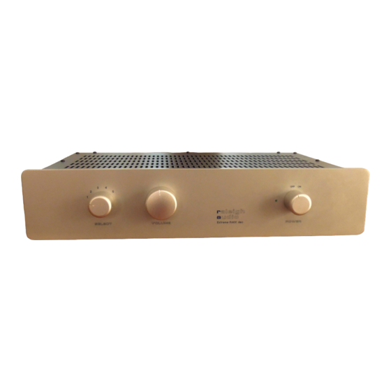
- Page 2 This completed Extreme RAKK dac has a silver face plate and knobs. A black faceplate and knobs is available. ...
-
Page 3: General Information
This kit is relatively straightforward to build, but assumes some prior skill with a soldering iron and some knowledge of electronic components and assembly. Kit version Use this manual with the Premium Extreme RAKK dac Mark IV • Use the applicable on-line manuals for component sub-assemblies. - Page 4 Warnings and Cautions Warning — a high voltage power supply (200VDC) is required to make the kit operate properly. These voltages can be lethal. If you are not familiar with safe techniques for completing the installation of this kit with a high voltage power supply, then you should seek someone who is qualified to help you construct this kit safely.
-
Page 5: Table Of Contents
Table of Contents General Information ..............................2 Table of Contents................................4 Component Parts ................................6 Assembly Instructions ..............................7 Assemble the Printed Circuit Boards ......................... 7 Pre-assemble (three-input) I2S Adapter with the RAKK dac ..................8 Pre-wire the printed circuit boards .......................... - Page 6 Document version history ............................64 ...
-
Page 7: Component Parts
Component Parts Depending upon the feature mix that you have chosen, the boards that you will assemble will vary. In all cases your project will include a RAKK dac, an Active Differential Output board, two Low-Voltage Power System Premium Regulators and a Low-Voltage Power System Standard Power Supply. -
Page 8: Assembly Instructions
Assembly Instructions Before you start, read through the instructions completely to the end. Inventory the kit contents to become familiar with the parts and to make sure you have everything. The assembly sequence is as follows: 1. Assemble all of the printed circuit boards 2. -
Page 9: Pre-Assemble (Three-Input) I2S Adapter With The Rakk Dac
Preassemble (threeinput) I2S Adapter with the RAKK dac ———————————————————————————— Skip this section if you do not have a (three-input) I2S Adapter. ———————————————————————————— If you have not yet done so, install the pulse transformers on the RAKK dac. 2. Mount four 3/8” standoffs on the bottom of the I2S Adapter and secure with 6-32 screws. 3. -
Page 10: Pre-Wire The Printed Circuit Boards
Prewire the printed circuit boards In the following steps, the wires should be inserted into the solder side of the board. “Preparing a wire” means to strip ⅛” of insulation from both ends of the wire and tin the ends. Because each wire has a “from” end and “to” end, and only one end is pre-wired, some pads are not wired in this section. -
Page 11: Pre-Wire The 10V Regulator (For The Rakk Dac)
Prewire the 10V Regulator (for the RAKK dac) ———————————————————————————— 3. Prepare a 20” #22 red/black twisted pair. • Connect the red wire to the DC Output “+” pad. • Connect the black wire to the DC Output “-” pad. ———————————————————————————— Skip the following step if you do not have a three-input I2S Adapter. 4. -
Page 12: Pre-Wire The 5V Regulator (For The Single-Input I2S Adapter)
Prewire the 5V Regulator (for the singleinput I2S Adapter) Skip this section if you do not have a single-input I2S Adapter. ———————————————————————————— 7. Prepare a 16” #22 red/black twisted pair. • Connect the red wire to the DC Output “+” pad. • Connect the black wire to the DC Output “-” pad. ————————————————————————————... -
Page 13: Pre-Wire The 12V Power Supply (For The Active Output)
Prewire the 12V Power Supply (for the Active Output) ———————————————————————————— 12. Install a 10K resistor in location R4. ———————————————————————————— 13. Prepare an 11” #22 red/black twisted pair. • Connect the red wire to the DC Output “+” pad. • Connect the black wire to the DC Output “-” pad. ————————————————————————————... - Page 14 18. Wire the AC cable that you just fabricated: • Strip and tin the end of the 4½” part of the black/white twisted pair. • Observing the same black/white orientation as the 5” black/white twisted pair that you just connected, connect this twisted pair to the outer-most “AC Input” pads. ————————————————————————————...
-
Page 15: Pre-Wire The Active Output
Prewire the Active Output ———————————————————————————— Wire the “From RAKK dac” inputs on the Active Output 1. Prepare a 4” #22 black wire. • Connect it to the “REF” pad. 2. Prepare a 4” #22 orange/black twisted pair. • Connect the orange wire to the “R+” pad. •... - Page 16 Wire the Ground on the Active Output 8. Connect a 13” #20 green wire to the “chassis” pad. ———————————————————————————— The Line Input pads are not used. ...
-
Page 17: Pre-Wire The Rakk Dac And I2S Interface Adapter (If Used)
Prewire the RAKK dac and I2S Interface Adapter (if used) ———————————————————————————— Wire the Input Select on the RAKK dac and I2S Interface Adapter The RAKK dac offers four inputs: three SPDIF or AES/EBU inputs and one I2S input. Inputs 1 through 3 are the SPDIF or AES/EBU inputs and Input 4 is always the I2S input, even if you are using only a single input. - Page 18 3. Connect the cable that you have prepared: • Connect the grey wire to the Input Select “com” pad. • Connect the blue wire to the Input Select pad selected by switch position 1. • Connect the orange wire to the Input Select pad selected by switch position 2. •...
-
Page 19: Pre-Wire The Power Transformer
Prewire the Power Transformer For the following steps, refer to the LL1683 Data sheet. ———————————————————————————— 1. Wire the transformer for your Mains line voltage: 115VAC: • Connect pin 2 to pin 12 with a #20 black wire. • Connect pin 4 to pin 10 with a #20 black wire. 230VAC: •... - Page 20 5. Wire the AC power for the 10V Regulator (for the RAKK dac) • Make a twisted-pair from a piece of 4½” long #20 grey wire, and a piece of 6¾” long #20 yellow wire. Align the wires evenly at one end. •...
-
Page 21: Panel Preparation
Panel Preparation Cut one 10” x 2” piece of damping material into two pieces: 10” x 1”. Cut another 10” x 2” piece of damping material into three pieces: Two, 8” x 1” and one, 2” x 2”. Cut the remaining 10” x 2” piece of damping material into four pieces: Two, 4”... -
Page 22: Back Panel Preparation
Top Panel Preparation 1. Place the top panel such that the inside surface of the panel faces up and the edge with the lip (front) is away from you. 2. Install one piece of 10” x 1” damping material on the inside of the top panel, centered between the vents and the lip. -
Page 23: Side Panel Preparation
Side Panel Preparation 1. Install an 8” x 1” piece of damping material centered on the inside of the left panel. 2. Install an 8” x 1” piece of damping material centered on the inside of the right panel. ———————————————————————————— Front Panel Preparation The position of damping material for the front panel will vary depending upon the switches and controls that you have chosen. -
Page 24: Panel Assembly
Panel Assembly Bottom Panel Assembly Steps preceded by a “note” (♪) deal with components which must be oriented properly. TIP – To ease the alignment of the mounting holes with standoffs, slightly loosen the standoffs from the board, install the screws through the bottom panel into the standoffs and then re-tighten the standoffs. - Page 25 ♪ Mount the 10V Regulator module for the RAKK dac. 2. Place the 10V Regulator module for the RAKK dac in its location next to the power transformer. Orient the board such that the AC Input is closest to the edge of the panel. Do not secure the board yet.
- Page 26 ♪ Mount the 5V Regulator module for the RAKK dac. 7. Place the 5V Regulator module for the RAKK dac in its location next to the 10V Regulator. Orient the board such that the AC Input is closest to the edge of the panel. Do not secure the board yet.
- Page 27 ♪ Mount the 5V Regulator module for the three-input I2S Adapter Skip this step if you do not have a three input I2S Adapter. 12. Place the 5V Regulator module for the I2S Adapter in its location on top of the standoffs on the 10V Regulator.
- Page 28 ♪ Mount the 5V Regulator for the single-input I2S Adapter. Skip this step if you do not have a single-input I2S Adapter. 15. Place the 5V Regulator module for the single-input I2S Adapter in its location on top of the standoffs on the RAKK dac 5V Regulator.
- Page 29 ♪ Mount the 8V Regulator for the USB Adapter. Skip this step if you do not have a USB Adapter. 18. Place the 8V Regulator module for the USB adapter in its location on top of the standoffs on the RAKK dac 5V Regulator. Orient the board such that the AC Input is closest to the edge of the panel.
- Page 30 ♪ Mount the Active Output board 21. Mount the Active Output board in its location in the center of the chassis. Orient the board such that the power input pads are closest to the power transformer. Do not secure the board yet. 22.
- Page 31 Mount the 12V Power Supply board 21. Dress the red/black twisted pairs from the 10V and 5V Regulators directly to the Active Output and then towards the front of the panel. ♪ 22. Place the Power Supply board in its location between the Active Output board and the transformer.
- Page 32 25. Locate the 11” red/black twisted pair that is connected to the 12V DC Output. • It will be connected to the 12V pads on the Active Output output board. • Connect the red wire to the “+” pad. • Connect the black wire to the “-” pad. 26.
- Page 33 Wire the I2S Adapter power Skip this section if you do not have an I2S Adapter. 30. Locate the red/black twisted pair that is connected to the 5V Regulator DC Output. • It will be connected to the 5V pads on the I2S Adapter. •...
-
Page 34: Back Panel Assembly
Back Panel Assembly You may have as few as one or as many as six input jacks. There are several types of input jacks and here are some general guidelines for mounting the jacks: • Mount the jacks from the inside of the panel. •... - Page 35 Mount the jacks and hardware: 1. Install the digital input jacks that you will be using. Do not install a USB Adapter or an I2S cable or Adapter at this time. 2. Install a male XLR connector in each of the two output locations. Mount an RCA jack in each of the two output locations.
- Page 36 Wire the chassis ground connections: 9. Connect a 5” #20 green wire from both center pins on the “RCA/XLR” switch to the ground buss. Solder both ends and dress the wire along the bottom edge of the panel. 10. If you have an I2S Adapter, prepare a 20” #20 green wire. Connect it to the ground buss. The next three steps deal with XLR jacks.
- Page 37 Wire the output jacks: 14. Connect the output jacks with #22 wire as follows: • Strip the insulation from a 3” black wire so that it is bare and tin just the tips. - Connect one end to pin 3 of the left XLR output jack. - Feed the wire through the tab on the RCA/XLR switch that is closest to the left XLR output jack.
- Page 38 Wire the input jacks: 15. Wire the SPDIF input (RCA jack) as follows: • Make a twisted pair from an 8” piece of violet #22 wire and a 10” piece of black #22 wire. • On the uneven end, strip 1¾” from the black wire and tin just the tip. •...
- Page 39 ———————————————————————————— ...
-
Page 40: Front Panel Assembly
Front Panel Assembly Suggestion: You may want to place a towel on your work surface to ensure that you don’t scratch the panel. ———————————————————————————— Skip the steps involving the select switch and volume control if you do not have those options. 1. Notice that the LED has one lead that is longer than the other. This identifies the functions of the leads –... -
Page 41: Final Assembly And Wiring
Final Assembly and Wiring ———————————————————————————— Wire the Bottom Panel to the Back Panel ———————————————————————————— Position the back panel on the back of the bottom panel and secure it with three 6-32 screws. Trim the length of these wires as needed in the following steps. Wire the AC Power and Ground 1. - Page 42 ———————————————————————————— Wire the Outputs 7. Connect the orange/black twisted pair from the Right Output RCA jack to the “Right Output” pads on the Active Output. Connect the orange wire to the “R+” pad and the black wire to the “R-” pad. 8.
- Page 43 Wire the RAKK dac Inputs 11. If you have chosen to have an SPDIF or AES/EBU Input 1, connect the violet/black twisted pair from that jack to the Input 1 pads on the RAKK dac. Connect the violet wire to the “+” pad and the black wire to the “-”...
- Page 44 Wire the USB Adapter and connect it to the RAKK dac Skip this section if you do not have a USB Adapter. Skip this step if you do have a 3-Input I2S Adapter. 18. Locate the red/black twisted pair from the 8V Regulator and connect it to the 8V pads on the USB Adapter.
- Page 45 ———————————————————————————— ...
-
Page 46: Wire The Bottom Panel To The Front Panel
Wire the Bottom Panel to the Front Panel Lay the front panel down adjacent to the bottom panel where it will be installed. ———————————————————————————— Trim the lengths of the wires as needed in the following steps. ————————————————————————————... - Page 47 Wire the Volume Control (skip this section if you do not have a volume control) 1. Connect the twisted pairs from the “volume control” pads on the Active Output board to the volume control as follows: • Connect the blue wire to the tab extending from the switch wafer closest to the front panel.
- Page 48 Wire the Select Switch (skip this section if you do not have a select switch) 2. Connect the cable from the Input Select pads on the RAKK dac as follows: • Connect the grey wire to the “A” tab of the Select switch. •...
- Page 49 Wire the Power-on LED 3. Locate the violet/white twisted pair from the 12V power supply board. 4. Solder the wires to the LED leads. • Connect the violet wire to the anode. The anode is the longer of the two leads. •...
- Page 50 Mount the Front Panel 8. Mount the front panel onto the bottom panel. • Remove the plastic covers from the studs now. • The stud in the center bottom of the front panel fits into the hole in the lip of the bottom panel.
-
Page 51: Assemble The Panels
Assemble the Panels The back panel has been temporarily mounted on the bottom panel so that the two panels could be wired together. Likewise, the front panel has been temporarily mounted on the bottom panel. You will now permanently mount and adjust all of the panels so that they fit together nicely. You will tighten the screws in a specific order. - Page 52 Position the Front panel 1. Tighten the KEP nut in the middle of front panel while lifting the front panel so it contacts the tops of the mounting holes. This ensures that it's straight with respect to the shelf it will be sitting on. 2.
- Page 53 ...
- Page 56 ...
-
Page 57: Final Adjustments
Final Adjustments Adjust the Constant Current Sources 1. Measure the resistance across resistor R29 and adjust potentiometer R30 so that the resistance across R29 is 25Ω. ———————————————————————————— 2. Measure the resistance across resistor R33 and adjust potentiometer R34 so that the resistance across R33 is 25Ω. ————————————————————————————... -
Page 58: Adjust The Front Panel Led
The adjustments that you are about to make interact. Therefore, the first time you may have to alternate adjustments to get them in range. ———————————————————————————— 9. Adjust the Left B+ to be 200V. Measure the voltage from the “Left B+” pad on the power board to the ground buss. Adjust R34. -
Page 59: Final Assembly
Final Assembly 1. You may optionally choose to apply a tiny drop of Loctite to the screws that hold the circuit boards in place – both top and bottom. This will ensure that the screws will not work loose over time or during shipment. Screws and nuts that have star lock washers do not need Loctite. -
Page 60: Parts List
Parts List Circuit kits Refer to the parts list for each of these kits. The following kits are provided. • RAKK dac Mark III • Active Differential Output • Low Voltage Power System Regulator (10V) • Low Voltage Power System Regulator (12V) Front Panel Options ... -
Page 61: Input Options
Input Options The back panel will be customized for the options that you have chosen. SPDIF Input Part Description RCA jack 1, 2 or 3 LL1572 pulse transformer 1, 2 or 3 AES/EBU Input Part Description XLR jack female, with tab 1, 2 or 3 Screw 4-40 x ⅜”... -
Page 62: Extreme Kit Contents
Extreme Kit Contents In addition to the parts in the circuit kits and options listed above, these parts are provided: Mechanical Parts Part Description Chassis set Top, bottom, front, back frame, two sides Back Panel custom Power switch Rotary, Knob For power switch AC inlet module Black with three prongs Fuse... - Page 63 Wire List From this, twisted pairs and individual pieces are called out in the individual assembly steps. Twisted wires are best made using a small electrical drill to do the twisting. Between 4 and 5 twists per inch is good. Be sure not to twist all the wire of a given color as some individual pieces are needed as well as twisted ones.
- Page 64 Hardware List Part Description Screw 4-40 x 0.375” button head 10 for the back panel plus 2 for each connector Screw 6-32 x 0.25” button head Screw 6-32 x 0.5” button head Screw 6-32 x 0.25” Phillips head Screw 4mm x 8mm button head 4-40 Kep nut (with star washer) 10 for the back panel plus 2 for each connector 6-32 Kep nut (with star washer)
- Page 65 Document version history Version Description Original document change select wiring colors...
Need help?
Do you have a question about the Premium Extreme RAKK dac and is the answer not in the manual?
Questions and answers