
Related Manuals for YASKAWA VIPA HMI cloudPanel H41-L1A41-0


Summary of Contents for YASKAWA VIPA HMI cloudPanel H41-L1A41-0
- Page 1 VIPA HMI TP-cloud | H41-L1A41-0 | Manual HB160 | TP-cloud | H41-L1A41-0 | en | 18-02 cloudPanel - TP104-CL www.vipa.com/en/service-support/manuals...
- Page 2 VIPA GmbH Ohmstr. 4 91074 Herzogenaurach Telephone: +49 9132 744-0 Fax: +49 9132 744-1864 Email: info@vipa.com Internet: www.vipa.com H41-L1A41-0_000_TP104-CL,1,EN - © 2018...
-
Page 3: Table Of Contents
VIPA HMI Table of contents Table of contents General........................4 1.1 Copyright © VIPA GmbH ................. 4 1.2 About this manual..................... 5 1.3 Safety information..................... 6 Hardware description..................... 7 2.1 Safety information for users................7 2.2 Properties......................8 2.3 Structure......................9 2.3.1 Overview...................... -
Page 4: General
VIPA HMI General Copyright © VIPA GmbH General 1.1 Copyright © VIPA GmbH All Rights Reserved This document contains proprietary information of VIPA and is not to be disclosed or used except in accordance with applicable agreements. This material is protected by the copyright laws. It may not be reproduced, distributed, or altered in any fashion by any entity (either internal or external to VIPA), except in accord- ance with applicable agreements, contracts or licensing, without the express written con- sent of VIPA and the business management owner of the material. -
Page 5: About This Manual
VIPA HMI General About this manual VIPA GmbH, Ohmstraße 4, 91074 Herzogenaurach, Germany Telefax: +49 9132 744-1204 EMail: documentation@vipa.de Technical support Contact your local VIPA Customer Service Organization representative if you encounter problems with the product or have questions regarding the product. If you are unable to locate a customer service centre, contact VIPA as follows: VIPA GmbH, Ohmstraße 4, 91074 Herzogenaurach, Germany Tel.: +49 9132 744-1150 (Hotline) -
Page 6: Safety Information
VIPA HMI General Safety information Supplementary information and useful tips. 1.3 Safety information Applications conforming The system is constructed and produced for: with specifications communication and process control general control and automation tasks industrial applications operation within the environmental conditions specified in the technical data installation into a cubicle DANGER! This device is not certified for applications in... -
Page 7: Hardware Description
VIPA HMI Hardware description Safety information for users Hardware description 2.1 Safety information for users Handling of electrostatic VIPA modules make use of highly integrated components in MOS-Technology. These sensitive modules components are extremely sensitive to over-voltages that can occur during electrostatic discharges. -
Page 8: Properties
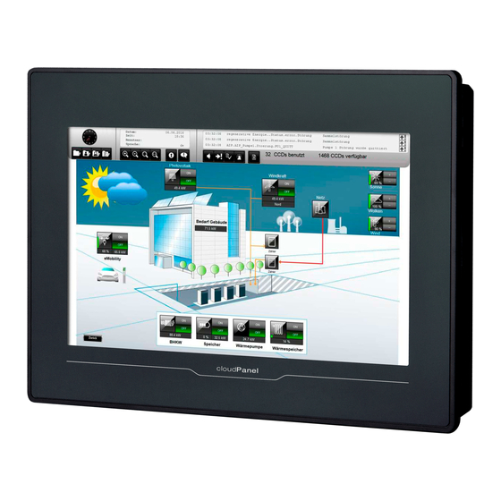
VIPA HMI Hardware description Properties 2.2 Properties General The VIPA cloudPanel allows you to visualize and alter operating states and recent process values of a connected PLC. The cloudPanel is a compact and modular Ò embedded PC based on Linux . -
Page 9: Structure
VIPA HMI Hardware description Structure > Overview 2.3 Structure 2.3.1 Overview Front view Interfaces Display with touch sensitive area (Touch-Screen) Bottom view USB-A interface USB 2.0 RJ45 jack for Ethernet communication LAN RS232/RS422/RS485 interface COM Slot for DC 24V voltage supply HB160 | TP-cloud | H41-L1A41-0 | en | 18-02... -
Page 10: Interfaces
VIPA HMI Hardware description Structure > Interfaces 2.3.2 Interfaces "Host"-USB-A Using the "Host"-USB-A interface USB mouse, keyboard, stick or USB hard discs can be connected. Ethernet connection The RJ45 jack provides the interface to the twisted pair cable, required for Ethernet. The Ethernet interface has got two LEDs for status display. -
Page 11: Memory Management
VIPA HMI Hardware description Structure > Memory management RS422/485 interface 9 pin SubD jack Logical states represented by voltage differences between the 4 cores Serial bus connection in 4-wire technology using full duplex mode Data communications up to a max. distance of 500m Data communication rate up to 115.2kBaud Serial bus connection in 2-wire technology using half duplex mode Power supply... -
Page 12: Dimensions
VIPA HMI Hardware description Dimensions USB storage media The connection of USB sticks and USB drives by use of the "Host"-USB-A interface is (USB 2.0) supported by the cloudPanel. 2.4 Dimensions Installation dimensions Front panel (L x H) 147 x 107 mm Depth (D+T) 26 + 5 mm Installation cutting (A x B) -
Page 13: General Data
VIPA HMI Hardware description General data 2.5 General data Conformity and approval Conformity 2014/30/EU EMC directive Approval Refer to Technical data others RoHS 2011/65/EU Restriction of the use of certain hazardous substances in electrical and electronic equipment Protection of persons and device protection Type of protection Rear: IP20;... - Page 14 VIPA HMI Hardware description General data Standard Comment Emitted interference EN 61000-6-4 Class A (Industrial area) Noise immunity EN 61000-6-2 Industrial area zone B EN 61000-4-2 8kV at air discharge (degree of severity 3), 4kV at contact discharge (degree of severity 2) EN 61000-4-3 HF field immunity (casing) 80MHz …...
-
Page 15: Technical Data
VIPA HMI Hardware description Technical data 2.6 Technical data Order no. H41-L1A41-0 Type cloudPanel TP104-CL Display Display size (diagonal) 4.3 " Display size (width) 95 mm Display size (height) 54 mm Resolution 272 x 480 / 480 x 272 Aspect ratio 16:9 Type of display TFT color (64K colors) - Page 16 VIPA HMI Hardware description Technical data Order no. H41-L1A41-0 COM1 connector Sub-D, 9-pin, male Serial, COM2 COM2 connector Number of USB-A interfaces USB-A connector USB-A (host) Number of USB-B interfaces USB-B connector Number of ethernet interfaces Ethernet Ethernet 10/100 MBit Ethernet connector RJ45 Integrated ethernet switch...
- Page 17 VIPA HMI Hardware description Technical data Order no. H41-L1A41-0 Minimum 1.5 mm Maximum front panel thickness 6 mm Net weight 291 g Weight including accessories 422 g Gross weight 658 g Environmental conditions Operating temperature 0 °C to 50 °C Storage temperature -20 °C to 70 °C Certifications...
-
Page 18: Deployment
VIPA HMI Deployment Installation Deployment 3.1 Installation Overview The cloudPanel is suitable for the installation in operating tables and control cabinet fronts. The installation happens via the backside. The cloudPanel is provided with a fixing technique that allows an easy connection with a crosstip screwdriver. A fast and easy device change is possible. -
Page 19: Commissioning
VIPA HMI Deployment Commissioning > Web browser 3.2 Commissioning CAUTION! – Before commissioning the device must be brought to room tempera- ture. – At condensation the device must be absolutely dry before connected to power. – To avoid overheat during operation the device must not be laid open to direct sun light. - Page 20 VIPA HMI Deployment Commissioning > Web browser www.vipa.com - With active internet connection, this button opens the VIPA home- page www.vipa.com. Settings - Use the [Settings] button to open the "System Settings" interface of the cloudPanel. Service & Support - With active internet connection, this button takes you directly to VIPA "Service &...
- Page 21 VIPA HMI Deployment Commissioning > Web browser ‘Toolbar visibility’ [Visible] - Toolbar visible [Hidden] / [Auto] - Toolbar hidden ‘Toolbar controls’ ‘Show navigation controls’ - Display of the buttons ‘Show location’ - Display of the address bar ‘Touch navigation’ - Display of the button ‘Zoom to fit contents’...
-
Page 22: System Settings
VIPA HMI Deployment Commissioning > System Settings 3.2.2 System Settings 3.2.2.1 Interface The cloudPanel has a "System Settings" interface to allow configuration of system options. The "System Settings" are accessible locally on cloudPanel or in remote using a current Web browser on port 443 (https://IP/machine_config). Username: admin Password: admin 3.2.2.2... - Page 23 VIPA HMI Deployment Commissioning > System Settings Logs Here you can enable the persistent log for BSP and have the possibility to export it under [Save]. Date & Time Here you can change the date and time of the cloudPanel including the time zone and the NTP server.
- Page 24 VIPA HMI Deployment Commissioning > System Settings Management Under Management the update of BSP components (Main OS, Config OS, Bootloader, XLoader) and the splash screen takes place. You will also receive information about the use and size of stored data here. The update of Main OS is available only in System Mode, the update of Config OS is only in User Mode.
- Page 25 VIPA HMI Deployment Commissioning > System Settings 3.2.2.3 Operation modes The "System Settings" have different operating modes: User Mode (Main OS Mode) – The cloudPanel is in factory default status, der Web browser is installed. – The User Mode allows to configure system parameters and update Config OS area.
- Page 26 VIPA HMI Deployment Commissioning > System Settings Web browser is running Click [Settings] on the blue splash screen, then enter the user name "admin" and the password "admin". The "System Settings" in User Mode is accessible remotely via web browser of the PC, enter https://<HMI_IP_address>.
- Page 27 VIPA HMI Deployment Commissioning > System Settings System Mode Normal operation - Web browser is not running (Config OS Mode) Click on [System Settings] on the black settings screen to enter in "System Set- tings" in User Mode. Select ‘Restart è Config OS’ to reboot in System Mode. Normal operation - Web-Browser is running Click on [Settings] on the blue splash screen to start "System Settings"...
- Page 28 VIPA HMI Deployment Commissioning > System Settings Recovery operation The "System Settings" are available in System Mode via a "Tap-Tap procedure" and can be accessed also when cloudPanel is facing a software failure. "Tap-Tap" con- sists in a sequence of several touch activations by simple means of the finger tapping the touch screen performed during the power-up phase and started immediately after the cloudPanel is powered on.
- Page 29 VIPA HMI Deployment Commissioning > System Settings Select the Web browser and click [Uninstall]. ð Uninstall process will be performed. Calibration mode Calibration mode allows to calibrate touch screen, can be accessed by "Tap-Tap" proce- dure. "Tap-Tap" consists in a sequence of several touch activations by simple means of the finger tapping the touch screen performed during the power-up phase and started immediately after the cloudPanel is powered on.
-
Page 30: Firmware Update
VIPA HMI Deployment Commissioning > Firmware update 3.2.3 Firmware update Requirement To execute the firmware update an empty USB stick (at least 1GB) in FAT32 format is necessary. Current firmware on The latest firmware versions can be found in the service area at www.vipa.com. www.vipa.com CAUTION! When installing a new firmware you have to be extremely careful. -
Page 31: Connection To A Plc System
VIPA HMI Deployment Connection to a PLC system 3.3 Connection to a PLC system Overview It is assumed that a WebVisu project has been created for your PLC. The feature for creating a WebVisu is integrated in the VIPA SPEED7 Studio. For more information on the VIPA SPEED7 Studio and how to create a web visualization, refer to the manual of your CPU or the online help of the SPEED7 Studio. -
Page 32: Installation Guidelines
VIPA HMI Installation Guidelines Basic rules for the EMC-equitable assembly of installations Installation Guidelines 4.1 Basic rules for the EMC-equitable assembly of installations General The installation guidelines contain information about the interference free deployment of a PLC system. There is the description of the ways, interference may occur in your PLC, how you can make sure the electromagnetic compatibility (EMC), and how you manage the isolation. - Page 33 VIPA HMI Installation Guidelines Basic rules for the EMC-equitable assembly of installations Coupling mechanism Cause Typical source Capacitate coupling Capacitate or electric coupling occurs Interference through parallel signal between conductors with different lines potential. The coupling is propor- Static discharge of the personnel tionate to the temporal change of the Contactors voltage.
- Page 34 VIPA HMI Installation Guidelines Basic rules for the EMC-equitable assembly of installations Proof the correct fixing of the lead isolation. – Data lines must be laid isolated. – Analog lines must be laid isolated. When transmitting signals with small ampli- tudes the one sided laying of the isolation may be favourable.
-
Page 35: Emc-Equitable Assembly
VIPA HMI Installation Guidelines EMC-equitable assembly 4.2 EMC-equitable assembly Mostly, measures for suppressing interference voltages are only taken, when the control is already in commission and the perfect receive of a wanted signal is disturbed. Causes for such interference's are in the most cases inadequate reference potentials, coming from mistakes at the device assembly and installation. -
Page 36: Emc-Equitable Cabling
VIPA HMI Installation Guidelines EMC-equitable cabling 4.3 EMC-equitable cabling Line routing Content of this section is the line routing of bus, signal and supply lines. Object of the line routing is to suppress the "slurring" at parallel lines. Line routing inside and For an EMC-equitable routing of the lines it is convenient to divide the cables in different outside of cubicles groups and install each group itself:... - Page 37 VIPA HMI Installation Guidelines EMC-equitable cabling Lightning protection CAUTION! Where cables and signal lines for PLC equipment are installed outside of buildings, the conditions for internal and external lightning protection must be satisfied. – Exterior lines should either be installed in metallic conduit pipes that is grounded on both ends or in steel-reinforced concrete cable trunks with continuously connected reinforcing.
- Page 38 VIPA HMI Installation Guidelines EMC-equitable cabling Avoid cables with foil-type screens as the foil can be easily damaged by tension and pressure at the point of attachment; this can result in reduced effectiveness of the screening action. As a rule you should always ground the screens of cables on both ends. This is the only way in which you can ensure that high frequency interference is attenuated prop- erly.
-
Page 39: Special Precautions Providing High Noise Immunity
VIPA HMI Installation Guidelines Special precautions providing high noise immunity 4.4 Special precautions providing high noise immunity Inductors require snubber Inductors controlled by your programmable controller (e.g. contactors and relays) do not networks normally require additional snubber networks or suppressors as the respective modules have been provided with the required components. -
Page 40: Checklist For The Emc-Compliant Installation Of Controllers
VIPA HMI Installation Guidelines Checklist for the EMC-compliant installation of controllers 4.5 Checklist for the EMC-compliant installation of controllers EMC-measures Space for Notes Connection of the inactive parts You should take special care to check the connections of: Module racks Frames Screen and protected earth conductor Are all the inactive metal parts interconnected by means of large-surface and low-...
Need help?
Do you have a question about the VIPA HMI cloudPanel H41-L1A41-0 and is the answer not in the manual?
Questions and answers