Table of Contents
Advertisement
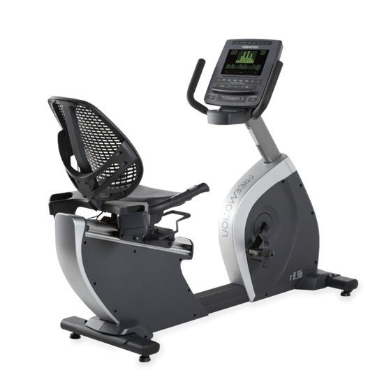
Model No. VMEX82018.0
Serial No.
Write the serial number in the space
above for reference.
Serial Number
Decal
QUESTIONS?
If you have questions, or if
parts are damaged or missing,
please see HOW TO CONTACT
CUSTOMER CARE on the back
cover of this manual.
CAUTION
Read all precautions and
instructions in this manual before
using this equipment. Keep this
manual for future reference.
USER'S MANUAL
freemotionfitness.com
Advertisement
Table of Contents

Related Manuals for Freemotion r8.9b


Summary of Contents for Freemotion r8.9b
- Page 1 Model No. VMEX82018.0 Serial No. USER’S MANUAL Write the serial number in the space above for reference. Serial Number Decal QUESTIONS? If you have questions, or if parts are damaged or missing, please see HOW TO CONTACT CUSTOMER CARE on the back cover of this manual.
-
Page 2: Table Of Contents
FREEMOTION and IFIT are registered trademarks of ICON Health & Fitness, Inc. App Store is a trademark of Apple Inc., registered in the U.S. and other countries. Android and Google Play are trademarks of Google LLC. -
Page 3: Important Precautions
Freemotion Fitness assumes no responsibility for personal injury or prop- erty damage sustained by or through the use of this product. -
Page 4: Before You Begin
R8.9B exercise bike. The manual. To help us assist you, note the product model ® R8.9B exercise bike provides an impressive selection number and serial number before contacting us. The of features designed to make your workouts more model number and the location of the serial number effective and enjoyable. -
Page 5: Part Identification Chart
PART IDENTIFICATION CHART Use the drawings below to identify the small parts needed for assembly. The number in parentheses below each drawing is the key number of the part, from the PART LIST near the end of this manual. The number following the key number is the quantity needed for assembly. -
Page 6: Assembly
ASSEMBLY • Assembly requires two persons. • The following tools (not included) are required for assembly: • Place all parts in a cleared area and remove the one adjustable wrench packing materials. Do not dispose of the packing materials until you finish all assembly steps. one Phillips screwdriver •... - Page 7 2. Attach the Front Stabilizer (50) to the Frame (1) with two M8 x 25mm Cap Screws (138), two M8 Split Washers (77), and two M8 x 16mm x 1.5mm Washers (110) (only one side is shown). 3. Orient the Large Accessory Tray (52) and the Seat Frame (18) as shown.
- Page 8 4. While a second person holds the Seat Frame (18) near the Seat Carriage (11), connect the wires (A) in the Seat Frame to the wires (B) in the Seat Carriage. Insert the excess wire into the Seat Carriage. Tip: Avoid pinching the wires. Attach the Seat Frame (18) to the Seat Carriage (11) with an M8 x 40mm Screw (105), an M8 Bright Split Washer (148), and an M8 x 25mm x 1.5mm...
- Page 9 6. Attach the Backrest Frame (14) to the Seat Frame (18) with four M6 x 35mm Screws (95); do not fully tighten the Screws yet. 7. Slide the Backrest (13) onto the Backrest Frame (14). Attach the Backrest (13) to the Backrest Frame (14) with four M6 x 15mm Screws (128), four M6 Split Washers (96), and four M6 x 1mm Washers (97);...
- Page 10 8. Attach the top of the Backrest (13) to the Backrest Frame (14) with two M4 x 25mm Screws (94), two M4 Washers (114), and two Backrest Spacers (39). 9. Have a second person hold the Upright (4) near the Frame (1). See the lower drawing.
- Page 11 10. Tip: Avoid pinching the wires. Attach the Upright (4) to the Frame (1) with four M8 x 20mm Avoid pinching Screws (93) and four M8 x 12mm x 1mm the wires Washers (92); start all the Screws, and then tighten them.
- Page 12 12. Attach the Small Accessory Tray (9) and the Accessory Tray Cover (42) to the Handlebar (47) with two M5 x 30mm Screws (88) and two M5 x 10mm Screws (89); start all the Screws, and then tighten them. 13. While a second person holds the Console (5) near the Handlebar (47), connect the wires (f) on the Console to the matching wires (g) in the Handlebar.
- Page 13 14. Tip: Avoid pinching the wires. Attach the Console (5) to the Handlebar (47) with four Avoid pinching M5 x 10mm Truss Screws (81); start all the the wires Truss Screws, and then tighten them. If you purchased the optional MYE receiver to set up a wall of TVs, go to step 15 to install the receiver. If you did not purchase the optional MYE receiver, go to step 16.
-
Page 14: How To Upgrade The Console
16. Tip: Avoid pinching the wires. Attach the Handlebar Cover (46) to the Handlebar (47) Avoid pinching with four M5 x 10mm Screws (89); start all the the wires Screws, and then tighten them. 17. Identify the right Pedal (29). Using an adjustable wrench, firmly tighten the right Pedal clock- wise into the Right Crank Arm (16). -
Page 15: How To Use The Exercise Bike
United States of America (excluding Alaska, Hawaii, and Canada) and are then subject to the terms provided by that country’s local authorized Freemotion Fitness, Inc. representative. - Page 16 CONSOLE DIAGRAM FEATURES OF THE CONSOLE You can also use the charging port on the console to charge your USB-compatible device while you The console offers an impressive array of features exercise. designed to make your workouts more effective and To activate the console, see page 17.
- Page 17 HOW TO ACTIVATE THE CONSOLE HOW TO TURN OFF THE CONSOLE If the exercise bike has a basic console, it can be If the pedals are not moved and no buttons are used with or without the power adapter. pressed for a short while, the console will turn off automatically.
- Page 18 HOW TO USE THE QUICK START MODE To select either the time display or the pace display for continuous display (priority mode), press the left 1. Turn on the console. Mode button repeatedly until a solid light appears next to the desired display. To return to the scan See HOW TO ACTIVATE THE CONSOLE on mode, press the left Mode button until a flashing page 17.
- Page 19 5. Measure your heart rate if desired. If the display does not show your heart rate, make sure that your hands are positioned as described. You can use the handgrip heart rate monitor or you Be careful not to move your hands excessively or can wear a Polar-compatible chest heart rate moni- to squeeze the contacts tightly.
- Page 20 HOW TO USE AN ONBOARD PROGRAM Note: The target heart rates are percentages of your maximum heart rate. Your maximum heart 1. Turn on the console. rate is estimated by subtracting your age from 220. For example, if you are 30 years old, your See HOW TO ACTIVATE THE CONSOLE on estimated maximum heart rate is 190 beats per page 17.
- Page 21 IMPORTANT: The target speed is intended only Race Training Program—Each program is divided to provide motivation. Make sure to exercise at into segments. During the program, the profile an intensity level that is comfortable for you. in the matrix will show your progress. The flash- ing segment of the profile represents the current If the resistance level is too high or too low, you segment of the program.
- Page 22 HOW TO CONNECT YOUR TABLET TO THE HOW TO CHANGE CONSOLE SETTINGS CONSOLE 1. Turn on the console. The console supports Bluetooth connections to tablets via the iFit–Smart Cardio Equipment app. Note: Other See HOW TO ACTIVATE THE CONSOLE on Bluetooth connections are not supported.
- Page 23 Pause Timeout—The selected pause time will Weight Loss button—Press this button to appear in the message banner. When the console select the digit 2. is paused, it will exit the workout or program after Speed Interval button—Press this button to the entered number of seconds if the pedals do not move and no buttons are pressed.
-
Page 24: Compliance Information
COMPLIANCE INFORMATION UNITED STATES FCC Statement. This equipment has been tested and found to comply with the limits for a Class B digital device, pursuant to Part 15 of the FCC Rules. These limits are designed to provide reasonable protection against harm- ful interference in a residential installation. -
Page 25: Maintenance And Troubleshooting
MAINTENANCE AND TROUBLESHOOTING MAINTENANCE If a replacement power adapter is needed, call the telephone number on the cover of this manual. IMPORTANT: To avoid damaging the console, use Inspect and tighten all parts of the exercise bike regularly. Replace any worn parts immediately. only a manufacturer-supplied regulated power adapter. -
Page 26: Exercise Guidelines
EXERCISE GUIDELINES Burning Fat—To burn fat effectively, you must exer- WARNING: cise at a low intensity level for a sustained period of Before beginning this time. During the first few minutes of exercise, your or any exercise program, consult your physi- body uses carbohydrate calories for energy. -
Page 27: Part List
PART LIST Model No. VMEX82018.0 R0619B Key No. Qty. Description Key No. Qty. Description Frame Receptacle Plug Battery Large Accessory Tray Hook and Loop Fastener Short Grip Upright Seat Handle Spring Console Handle Bushing M8 Nut Ground Wire Wear Cover Wheel Idler Bearing Coupler... - Page 28 Key No. Qty. Description Key No. Qty. Description M4 x 16mm Self-tapping Screw Handlebar Cover Cap M5 x 16mm Screw Crank Bearing M8 x 20mm Hex Screw Crank Spacer Roller Sleeve Bearing Spacer M8 x 40mm Screw M4 x 10mm Screw Roller M5 x 12mm x 1mm Washer Roller Axle...
-
Page 29: Exploded Drawing
EXPLODED DRAWING A Model No. VMEX82018.0 R0619B... - Page 30 EXPLODED DRAWING B Model No. VMEX82018.0 R0619B 106 106 107...
- Page 31 EXPLODED DRAWING C Model No. VMEX82018.0 R0619B...
-
Page 32: How To Contact Customer Care
WHAT TO DO IF SERVICE IS REQUIRED WARRANTY PERIODS AND COVERAGE Freemotion Fitness warranty service may be obtained by Freemotion Fitness warrants this product to be free from contacting the authorized dealer from which you purchased defects in workmanship and material under normal use and this product.
Need help?
Do you have a question about the r8.9b and is the answer not in the manual?
Questions and answers