Table of Contents
Advertisement
Quick Links
Distributed by: ABQ Industrial LP USA
Tel: +1 (281) 516-9292 / (888) 275-5772 eFax: +1 (866) 234-0451
Web: https://www.abqindustrial.net E-mail: info@abqindustrial.net
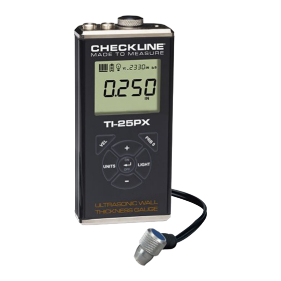
MODEL TI-25PX
ULTRASONIC THICKNESS GAUGE
Operating Manual
Distributed by: ABQ Industrial LP USA
Tel: +1 (281) 516-9292 / (888) 275-5772 eFax: +1 (866) 234-0451
Web: https://www.abqindustrial.net E-mail: info@abqindustrial.net
Advertisement
Table of Contents

Related Manuals for ABQ Industrial TI-25PX


Summary of Contents for ABQ Industrial TI-25PX
- Page 1 Distributed by: ABQ Industrial LP USA Tel: +1 (281) 516-9292 / (888) 275-5772 eFax: +1 (866) 234-0451 Web: https://www.abqindustrial.net E-mail: info@abqindustrial.net MODEL TI-25PX ULTRASONIC THICKNESS GAUGE Operating Manual Distributed by: ABQ Industrial LP USA Tel: +1 (281) 516-9292 / (888) 275-5772 eFax: +1 (866) 234-0451...
-
Page 2: Table Of Contents
TABLE OF CONTENTS Introduction .......................... 1.1 Disclaimer Keypad, Menu, Display & Connectors ................2.1 ON/OFF/ENTER Key0 2.2 PRB 0 Key 2.3 VEL Key 2.4 LIGHT Key 2.5 UNITS Key 2.6 +/- INCREMENT/DECREMENT Keys 2.7 The Display 2.8 The Transducer 2.9 Top End Cap Principals of Ultrasonic Measurement ................ -
Page 3: Disclaimer
1.0 INTRODUCTION The Checkline model TI-25PX is a basic dual element thickness gauge with the ability to locate blind surface pitting and internal defects/flaws in materials. Based on the same operating principles as SONAR, the TI-25PX is capable of measuring the thickness of various materials with accuracy as high as ±... -
Page 4: Keypad, Menu, Display & Connectors
PRB 0 Key The PRB 0 key is used to “zero” the TI-25PX in much the same way that a mechanical micrometer is zeroed. If the gauge is not zeroed correctly, all of the measurements that the gauge makes may be in error by some fixed value. -
Page 5: Light Key
The Display The TI-25PX uses a custom glass LCD backlit low temperature display for use in a variety of climate conditions. It contains graphic icons, as well as both 7 and 14 segment display areas. Let’s take a closer look and what all these things are telling us: NOTE: This display is used for multiple gauge models in the TI series. -
Page 6: The Transducer
Refer to section 6.3 for an explanation on locking the TI-25PX. 2.8 The Transducer The transducer is the “business end” of the TI-25PX. It transmits and receives ultrasonic sound waves that the TI-25PX uses to calculate the thickness of the material being measured. - Page 7 The transducer must be used correctly in order for the TI-25PX to produce accurate, reliable measurements. Below is a short description of the transducer, followed by instructions for its use. This is a bottom view of a typical transducer. The two semicircles of the wear face are visible, as is the barrier separating them.
-
Page 8: Top End Cap
Top End Cap The top end cap is where all connections are made to the TI-25PX. The diagram above shows the layout and description of the connectors. Transducer Connectors Refer to Diagram: The transducer connectors and battery cover/probe zero disk are located on the TI-25PX’s top end cap. -
Page 9: Principals Of Ultrasonic Measurement
3.0 PRINCIPALS OF ULTRASONIC MEASUREMENT Time versus thickness relationship Ultrasonic thickness measurements depend on measuring the length of time it takes for sound to travel through the material being tested. The ratio of the thickness versus the time is known as the sound velocity. In order to make accurate measurements, a sound velocity must be determined and entered into the instrument. -
Page 10: Temperature
If the manual mode has been selected, the transducer is placed on the reference disk located on top of the TI-25PX, and the PRB 0 key pressed to establish a zero point for the transducer connected. If the Auto Zero feature is enabled, simply pressing the PRB 0 key will perform an electronic zero to establish the same zero point. - Page 11 V-Path Correction Dual element delay line transducers have two piezoelectric elements focused towards one another at a slight angle, mounted on a delay line. One element is used for transmitting sound, while the other element receives the sound reflection. The two elements and their delay lines are packaged in a single housing but acoustically isolated from each other with an insulated sound barrier.
-
Page 12: Selecting The Measurement Mode
4.0 SELECTING THE MEASUREMENT MODE Which mode & transducer do I use for my application? High penetration plastics and castings: The most common mode for these types of applications is pulse-echo. Cast iron applications require 1 – 5MHz frequencies, and cast aluminum requires a 7 –... -
Page 13: Making Measurements
Material Type section 5.3. Probe zero Setting the zero point of the TI-25PX is important for the same reason that setting the zero on a mechanical micrometer is important. It must be done prior to calibration, and should be done throughout the day to account for any temperature changes in the probe. - Page 14 If the material velocity is known, it can be manually entered into the TI-25PX. If the exact material velocity is unknown, a common velocity can initially be entered to set the TI-25PX close to the unknown target velocity, followed by multiple fine adjustments to the velocity value until the target velocity is discovered.
-
Page 15: Additional Features
Lock The lock feature was built into the TI-25PX for the purpose of locking the operators out of editing any of the gauge settings, for purposes of consistency between operators. When the lock feature is enabled, the gauge calibration functionality cannot be altered, as well as any of the individual features in the gauge. -
Page 16: Factory Defaults
TI-25PX on. Factory Defaults The TI-25PX can be reset to factory defaults at any time to restore the original gauge settings. This should only be used if the gauge is not functioning properly, or perhaps multiple features have been enabled and a clean start is needed. -
Page 17: Appendix A - Velocity Table
7.0 APPENDIX A – SOUND VELOCITY TABLE Material Sound Velocity in/us Sound Velocity m/s Aluminum 0.2510 6375 Beryllium 0.5080 12903 Brass 0.1730 4394 Bronze 0.1390 3531 Cadmium 0.1090 2769 Columbium 0.1940 4928 Copper 0.1830 4648 Glass (plate) 0.2270 5766 Glycerine 0.0760 1930 Gold... -
Page 18: Appendix B- Application Notes
At such elevated temperatures, it is recommended that the user perform calibration on a sample piece of known thickness, which is at or near the temperature of the material to be measured. This will allow the TI-25PX to correctly calculate the velocity of sound through the hot material. - Page 19 Measuring laminated materials Laminated materials are unique in that their density (and therefore sound-velocity) may vary considerably from one piece to another. Some laminated materials may even exhibit noticeable changes in sound-velocity across a single surface. The only way to reliably measure such materials is by performing a calibration procedure on a sample piece of known thickness.
-
Page 20: Warranty
Distributed by: ABQ Industrial LP USA Tel: +1 (281) 516-9292 / (888) 275-5772 eFax: +1 (866) 234-0451 Web: https://www.abqindustrial.net E-mail: info@abqindustrial.net 9.0 WARRANTY ELECTROMATIC Equipment Co., Inc. (ELECTROMATIC) warrants to the original purchaser that this product is of merchantable quality and confirms in kind and quality with the descriptions and specifications thereof.
Need help?
Do you have a question about the TI-25PX and is the answer not in the manual?
Questions and answers