Table of Contents
Advertisement
Quick Links
Distributed by: ABQ Industrial LP USA
Tel: +1 (281) 516-9292 / (888) 275-5772 eFax: +1 (866) 234-0451
Web: https://www.abqindustrial.net E-mail: info@abqindustrial.net
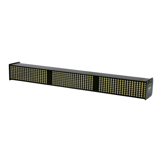
Stationary Stroboscope
Model LS-36-LED
Distributed by: ABQ Industrial LP USA
Tel: +1 (281) 516-9292 / (888) 275-5772 eFax: +1 (866) 234-0451
Web: https://www.abqindustrial.net E-mail: info@abqindustrial.net
Advertisement
Table of Contents

Related Manuals for ABQ Industrial LS-36-LED


Summary of Contents for ABQ Industrial LS-36-LED
- Page 1 Distributed by: ABQ Industrial LP USA Tel: +1 (281) 516-9292 / (888) 275-5772 eFax: +1 (866) 234-0451 Web: https://www.abqindustrial.net E-mail: info@abqindustrial.net Stationary Stroboscope Model LS-36-LED Distributed by: ABQ Industrial LP USA Tel: +1 (281) 516-9292 / (888) 275-5772 eFax: +1 (866) 234-0451...
-
Page 2: Table Of Contents
Table of Contents 1.0 Introduction ....................... 1.1 Unpacking 1.2 Optional Accessories 2.0 Safety Information ....................3.0 Controls ........................4.0 Installation/Mounting ....................5.0 Connection ........................ 5.1 Typical connections 6.0 Operation ........................6.1 Aligning the unit and switching it on 6.2 Switching between sockets 1 and 2 6.3 Adjusting the flash duration 7.0 Technical Data ...................... -
Page 3: Introduction
1.0 Introduction The LS-36-LED stroboscope is shipped ready for assembly and use. Unpacking Unpack the gauge and inspect it for any shipping damage. Notices of defect must be filed immediately, in writing, at the latest within 10 days on receipt of the goods. -
Page 4: Safety Information
The LS-36-LED must only be used in accordance with these operating instructions. The LS-36-LED must not be altered in any way. The manufacturer will not be liable for any damage resulting from incorrect or improper use. This will also render the guarantee null and void. -
Page 5: Controls
3.0 Controls On the rear side of the device you will find the following controls. Use of these controls is explained in the following section: Input #1 External Trigger Input #2 Power Input Trigger Output Select Switch (SLAVE) Brightness/Sharpness Adjustment Knob Multi-Turn Pot 1. -
Page 6: Installation/Mounting
4.0 Installation/Mounting Mount the strobe in the desired location using the threaded inserts located on the underside of the strobe housing (shown below). There are two (2) M5 metric threaded inserts and one (1) 1/4-20 inch threaded insert. Use appropriated plate and screw to attach to customer-supplied mounting fixture. -
Page 7: Connection
PNP and NPN signals. A matching plug for these input sockets is included with the LS-36-LED. • Do not trigger the LS-36-LED with signals above 120,000 FPM. RECOMMENDATION! Use a shielded cable to connect the trigger signal. - Page 8 Typical connection examples: Please take connection examples from Figures 2 to 5. Please note that you will need optional accessories for some of the examples (stroboscope control unit, AC Adapter, sensor). A. Trigger signal and supply voltage from external equipment (Fig. 2). B.
- Page 9 RT Strobe eco control), supply voltage from optional AC adapter (Fig. 5). The power is either supplied by the LS-36-LED power supply unit (available as an option) or the equipment being observed. The LS-36-LED requires an external trigger source. Possible trigger sources include a stroboscope control unit, an external machine or a sensor.
-
Page 10: Operation
6.0 Operation Aligning the unit and switching it on. 1. Point the stationary stroboscope at a moving object and switch it on. The red LED inside the rocker switch indicates that it is ready for use. If the LED flashes, the unit is connected to the voltage supply but no trigger signal is present. -
Page 11: Technical Data
7.0 Technical Data General Parameters Frequency range 0 to 120,000 FPM (flashes per minute) Power supply 24 VDC (+/– 10%) DIN 415245-pin standard plug Universal AC/DC power supply Power consumption 40 Watt External trigger input 3 to 30 V / max. 5 mA potential-free optocoupler DIN 41524 5-pin standard plug Uout = Uin, max. -
Page 12: Warranty
Distributed by: ABQ Industrial LP USA Tel: +1 (281) 516-9292 / (888) 275-5772 eFax: +1 (866) 234-0451 Web: https://www.abqindustrial.net E-mail: info@abqindustrial.net 8.0 Warranty The manufacturer warrants to the original purchaser that this product is of merchantable quality and confirms in kind and quality with the descriptions and specifications thereof.
Need help?
Do you have a question about the LS-36-LED and is the answer not in the manual?
Questions and answers