Advertisement
Quick Links
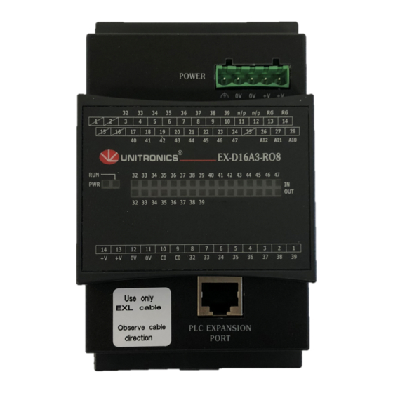
EX-D16A3-RO8
®
The Unitronics
EX-D16A3-RO8 is an XL I/O expansion module for use in conjunction with specific Unitronics controllers.
XL modules comprise enhanced I/O configurations and detachable I/O connectors. In addition, this module comprises a built-in
adapter for communicating with the PLC and providing power to the other expansion modules in the system.
This module provides:
16 digital inputs, including 2 HSC
3 analog inputs
8 relay outputs
For additional information and technical specifications, visit the Technical Library at
Component Identification
1
Power supply connector
2
Status indicators
3
Output connector
4
Output power supply connection points
5
PLC expansion port (for communication with the PLC)
6
Input/output status indicators
7
Module-to-module connector port
8
Input connectors
Failure to comply with appropriate safety guidelines can
cause severe personal injury or damage to property.
Only qualified personnel should service and operate this
device.
When power is turned on, do not connect or disconnect the
device to avoid damaging the system.
Mounting the Module
To mount the module on a 35mm DIN-rail, snap it squarely onto
the DIN-rail, as shown below.
Install the module in an upright position.
To ensure good ventilation, leave at least 50mm between the
device and all other objects above or below it.
Install at a maximum distance from high-voltage cables and
power equipment.
Unitronics
XL I/O Expansion Module (Built-in Adapter)
Installation Guide
w
ww.unitronics.com.
0 H
1
2
3
4
Connecting Modules
To connect a module to the adapter or expansion module:
1. Push the module-to-module connector (1) into the port
(2) located on the right side of the module or adapter.
2. Push the protective cap (3) into the connector port of
the last module. The cap is supplied with the adapter.
8
7
6
5
1
Advertisement

Subscribe to Our Youtube Channel
Related Manuals for Unitronics EX-D16A3-RO8


Summary of Contents for Unitronics EX-D16A3-RO8
- Page 1 ® The Unitronics EX-D16A3-RO8 is an XL I/O expansion module for use in conjunction with specific Unitronics controllers. XL modules comprise enhanced I/O configurations and detachable I/O connectors. In addition, this module comprises a built-in adapter for communicating with the PLC and providing power to the other expansion modules in the system.
- Page 2 To PLC and the other To Adapter; insert accordingly. The module is supplied with a 1-meter cable, part number EXL-CAB100. Other cable lengths are also available. Use only an original Unitronics cable and do not make any changes to it. Wiring Considerations Use crimp terminals for wiring and use 26-12 AWG wire Install an external circuit breaker.
- Page 3 (negative logic) inputs 32-39 npn (negative logic) inputs 40-47 Wiring Analog Inputs The following diagram shows the 2-wire and 4-wire current connection. Use shielded twisted pair cable. Connect shields to the earth ground at the signal’s source. Unitronics EX-D16A3-RO8...
- Page 4 Connecting RG Pins For correct operation of digital and analog inputs and for EMI immunity, connect the RG pin of all the expansion modules containing RG signals to the adapter module 0V signal. The overall length of the wire connecting the RG pins to the adapter 0V signal must be less than 3 meters. Connect the RG pins in series (daisy chain).
Need help?
Do you have a question about the EX-D16A3-RO8 and is the answer not in the manual?
Questions and answers
have an error message and the #32 lights up red. Only have asterisk were the length numbers should be